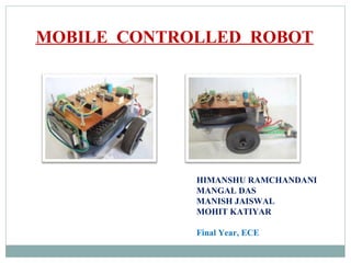
3. SPECIFICATIONS
Standard features are used.
Cell phones used for the connection should be specified
models like Nokia 1100, Nokia 1600.
Working communication through a hands-free jack.
Connection between cell phones are manually activated.
System is an open-loop system.
4. TECHNOLOGY
DUAL-TONE MULTI-FREQUENCY (DTMF)
Dual Tone Multi Frequency (DTMF) tone is the
signal to the network center that is generated when
any key of telephone is pressed.
With DTMF, each key pressed on phone, generates
two tones of specific frequencies.
One tone is generated from a high-frequency group
of tones and the other from a low frequency group.
5. TECHNOLOGY
The row in which the key appears determine the low
frequency, and column determine the high frequencies.
For example, pressing the ‘1’ key will result in a
sound composed of both a 697 Hz and a 1209 Hz tone.
DUAL-TONE MULTI-FREQUENCY (DTMF)
FIG: FREQUENCY TABLE
6. HT9170 series IC’s are DTMF
tone receivers.
They are integrated with Digital
Decoder.
Detects and decode all the 16
DTMF tone pairs into 4 bit code.
DTMF DECODER
FIG: PIN DIAGRAM
7. FIG:CIRCUIT CONNECTION
DTMF DECODER
Built-in Dial tone rejection
circuit eliminates the need of
pre- filtering.
When input signals are
recognized to be effective,
DV becomes high, and the
correct tone code (DTMF)
digit is transferred.
The low group filter filters
low group frequency signal
output whereas the high
group filter filters high group
frequency signal output.
12. WORKING
A.) INPUT MODE
Input is given from hands-free connected to mobile
(stacked on Robot).
Input is a DTMF Tone sent through a mobile far distant
from Robot.
HT9170 series decoder is used at input.
Detect and decode all the 16 DTMF tones pairs into a 4-
bit code output .
13. 4 bit binary code bit pattern is generated as D0,.D1,D2,D3
(Pin 11, Pin 12, Pin 13, Pin 14 of HT9170).
WORKING
DTMF
TONE
PC6 PC5 PC4 PC3 PC2 PC1 PC0
2 1 --- --- 1 1 0 1
4 1 --- --- 1 0 1 1
6 1 --- --- 1 0 0 1
8 1 --- --- 0 1 1 1
* 1 --- --- 0 0 1 1
FIG: INPUT TABLE FOR DTMF TONES
14. WORKING
B.) PROCESSING MODE
Output from HT9170 is given at input pins of the NOT
Gate inverter IC 7414 ( Pin 1, Pin3, Pin 5, Pin 9).
This output is given to the microcontroller’s
(ATmega8) input port (as assigned in programming as
Port C). Pin 23, Pin 24, Pin 25, pin 26.
The Pin 1 of the microcontroller is used as the reset pin.
A 12 MHz crystal clock is used between Pin 9 and
Pin10 along with 2 capacitors C1 and C2
15. PINS OF MICROCONTROLLER NAMES FOR PROGRAMMING PORT
17 MOSI
18 MISO
19 SCK
1 RESET
7 VCC
8 GND
The Pin 1 , Pin7, Pin 8 , Pin 17, Pin 18, Pin 19 of
microcontroller are used for programming of the
controller.
The output of the microcontroller are taken from Pin 14,
Pin 15, Pin 16, Pin 17.
WORKING
FIG: CONFIGURATION OF MICRONTROLLER PINS
16. WORKING
C.) OUTPUT MODE
The Motor Driver IC L293d
is used for controlling the
motion of the motors .
The Pin 2, Pin 7, Pin 10 and
Pin 15 are the input pins of
L293d IC
Output pins are configured as
Pin 3, Pin 6, Pin 11, and Pin
14.
FIG: L293D IC
18. In this mode, the ROBOT perform general motions i.e., Forward,
Backward, Left and Right.
Forward Motion:- Both the Motors operate (In Forward direction).
Backward Motion:- Both the Motors operate. (In Backward Direction)
Left Motion:- Right Motor operate and Left Motor is stopped.
Right Motion:- Left Motor operate and Right Motor is stopped.
DTMF TONE PB3 PB2 PB1 PB0 MOTION#
2 1 0 0 1 FORWARD
4 0 0 0 1 LEFT
6 1 0 0 0 RIGHT
8 0 1 1 0 BACKWARD
* 0 0 0 0 STOP
MOTION OF MOTORS