Choice of Numerical Integration Method for Wind Time History Analysis of Tall...
s1756973715500080
1. 2nd Reading
December 1, 2015 14:9 WSPC/245-JMM 1550008
Journal of Multiscale Modelling
Vol. 6, No. 3 (2015) 1550008 (17 pages)
c Imperial College Press
DOI: 10.1142/S1756973715500080
Virtual Testing of Large Composite Structures:
A Multiple Length/Time-Scale Framework
Luigi Gigliotti and Silvestre T. Pinho
Department of Aeronautics
Imperial College London
South Kensington Campus, London
SW7 2AZ, United Kingdom
Published 4 December 2015
This paper illustrates a multiple length/time-scale framework for the virtual testing
of large composite structures. Such framework hinges upon a Mesh Superposition Tech-
nique (MST) for the coupling between areas of the structure modelled at different length-
scales and upon an efficient solid-to-shell numerical homogenization which exploits the
internal symmetries of Unit Cells (UCs). Using this framework, it is possible to mini-
mize the areas of the structure modelled at the lowest- (and computationally demanding)
scales and the computational cost required to calculate the homogenised to be used in the
higher-scales subdomains of multiscale FE models, as well as to simulate the mechanical
response of different parts of the structure using different solvers, depending on where
they are expected to provide the most computationally efficient solution. The relevance
and key-aspects of the multiple length/time-scale framework are demonstrated through
the analysis of a real-sized aeronautical composite component.
Keywords: Virtual testing; large composite structures; multiple length/time-scale.
Mathematics Subject Classification:
1. Introduction
1.1. Virtual testing of large composite structures
To address complex industrial structural challenges, such as the design of the com-
posite central wing box of the Airbus A380,1
virtual testing methods have been
exploited.2
The extensive use of virtual testing based on nonlinear FE analyses is
envisioned to be a key-aspect towards an increased confidence in the real-scale and
expensive structural tests required for certification; furthermore, virtual testing
provides useful insight into the likelihood, causes and consequences of structural
failure.3–5
However, to be fully established in structural design and certification,
virtual testing methods need to be validated against all level of structural testing,
from the coupon-level (e.g., material specimens) to the system-level (e.g., wing or
fuselage).6
1550008-1
J.MultiscaleModellingDownloadedfromwww.worldscientific.com
byIMPERIALCOLLEGELONDONon12/15/15.Forpersonaluseonly.
2. 2nd Reading
December 1, 2015 14:9 WSPC/245-JMM 1550008
L. Gigliotti & S. T. Pinho
Within this framework, the virtual testing of large-scale composite structures
for industrial applications entails significant challenges; the latter are primarily
ascribable to the inherently multiscale nature of composite materials and, as a
result, to their highly complex failure modes.7
For the efficient structural design of
large composite components, their virtual testing often requires that different parts
of the structure are modelled at multiple length- and time-scales, eventually even
using different physics. Therefore, it is crucial to develop:
(i) suitable techniques for coupling areas of the structure modelled at different
length-scales, i.e., discretized using different finite element types;
(ii) numerical methods to efficiently compute equivalent homogenized properties to
be used in both 2D FE models and in the lower-scale subdomains of multiscale
FE models of large composite components.
1.2. Multiscale coupling
The coupling of subdomains discretized with finite elements of different physical
dimension/formulation can introduce artificial stresses at the shared boundaries.8,9
Hence, the stress and strain fields within the structure and its mechanical response
may not be correctly simulated. This may lead, in problems involving failure, to
a low-fidelity damage pattern prediction: furthermore, in dynamic problems, the
interfaces between differently-discretized subdomains might artificially reflect stress
waves.11,12
Global/local approaches can be categorized as coupled and uncoupled
approaches.10
In the former, the coupling between the local and global models
(discretized using different finite elements) is enforced through Multi-Point Con-
straints (MPC). Numerous mixed-dimensional coupling techniques based on MPCs
are available in literature.8,13,14
Compared to standard solid-to-shell coupling, these
methodologies are shown to attenuate the undesirable stress disturbances at the
interface between differently-discretized subdomains; nevertheless, the derivation
of the suitable MPC equations for generally orthotropic materials may become
computationally impracticable.14
Alternatively, D´avila9
demonstrated that the use
of ad hoc transition elements allows to faithfully resolve the stress and strain fields
within both the local and global models in the proximity of the interfaces.
In uncoupled global/local approaches, the displacements/tractions obtained
from a higher-scale global model are used to prescribe the boundary conditions for
the lower-scale local model. The series of higher-scale analysis followed by a lower
scale analysis can be run once (a typical example is the Submodelling technique
available in Abaqus15
), or iteratively until convergence of the forces and moments
on the local/global interface is obtained. As a result, these approaches are difficult
to automate and pose significant challenges in terms of computational resources;
furthermore, they might be inaccurate if damage and failure propagation within the
1550008-2
J.MultiscaleModellingDownloadedfromwww.worldscientific.com
byIMPERIALCOLLEGELONDONon12/15/15.Forpersonaluseonly.
3. 2nd Reading
December 1, 2015 14:9 WSPC/245-JMM 1550008
Virtual Testing of Large Composite Structures
local model significantly affect the response of the global model. Reinoso et al.16,17
compared the Submodelling technique (uncoupled approach) to Shell-to-Solid cou-
pling (coupled approach). In the latter works, stress disturbances were observed at
the local/global boundaries for both approaches; as a result, the correct identifica-
tion of the damage extension might be jeopardized.
To enhance the computational efficiency of multi-scale approaches, it is desir-
able that the size of the lower-scale model is kept to a minimum. However, the
global/local transition should be sufficiently distant from any perturbation such
as boundaries or damaged zones which could potentially interact with the stress
disturbance at the discretization transition. The influence of the distance of the
global/local transition from the delamination front was investigated by Krueger
et al. for the cases of delaminated test specimens18,19
as well as skin/stringer
debonding in an composite aircraft component.20,21
The need of having the global/local transition at a sufficient distance from any
boundaries/damaged areas often leads to overly large models at the lower-scales; as
a result, the computational efficiency of the analysis might not be optimal. Thus,
to fully exploit the computational advantages provided by multiscale approaches,
it is of paramount importance to use a local/global coupling technique which:
(i) avoids the presence of artificial stress disturbances, as well as the unrealis-
tic stress wave reflections observed at the boundaries between differently dis-
cretized subdomains;
(ii) allows to minimize the size of the areas that are required to be modelled at the
lower length-scales.
1.3. Solid-to-shell homogenization
For the virtual testing of large composite structures, FE (preferably 2D) models
with homogenised material properties are usually preferred to high-fidelity 3D FE
models. Furthermore, shell-based FE models with equivalent homogenized prop-
erties are used in the higher-scale subdomains of multiscale FE models of large
composite components.
The numerical homogenization of periodic structures is often carried out through
the analysis of the mechanical response of Unit Cell (UC) models, where the com-
posite microstructure is modelled at the lowest length/scale of interest. Numer-
ous studies focused on the determination and use of UCs,22,23
as well as on the
appropriate periodic boundary conditions (PBCs) that need to be applied for
their analysis.24–27
However, as a result of the increasing complexity of composite
microstructures, e.g., textile and NCF composites, pin-reinforced sandwich struc-
tures, etc., the computational cost associated to modelling/meshing and analysis
might become burdensome.
To circumvent this difficulty, several authors have proposed to exploit (whenever
they exist) internal symmetries of the UCs, thus enabling a significant reduction of
1550008-3
J.MultiscaleModellingDownloadedfromwww.worldscientific.com
byIMPERIALCOLLEGELONDONon12/15/15.Forpersonaluseonly.
4. 2nd Reading
December 1, 2015 14:9 WSPC/245-JMM 1550008
L. Gigliotti & S. T. Pinho
the analysis domain. Analysis domains smaller than UCs are denoted as reduced
Unit Cells (rUCs) and have successfully been used for the analysis UD compos-
ites,28
particle-reinforced composites29
and textile composites.30–32
However, in
these works address the issue of using rUCs for obtaining equivalent 3D homogenised
properties, without considering the computation of equivalent 2D homogenised
properties.
The efficient computation of the equivalent homogenized properties to be used
in both 2D FE models and in the higher-scale subdomains of multiscale FE models
of large composite components hinges upon the development of a mathematical
framework which:
(i) enables the direct two-scale (solid-to-shell) homogenization of periodic struc-
tures, including their bending and twisting response;
(ii) enables the use of rUCs.
1.4. Structure of this paper
In this paper, we illustrate the capabilities of a multiple length/time-scale frame-
work for the virtual testing of large composite structures.
The multiple length/time-scale framework is described in Sec. 2 and its primi-
tives are illustrated and discussed, respectively in Secs. 3 and 4, through the sim-
ulation of a real-sized helicopter rotor blade subjected to a low-velocity impact;
conclusions are drawn in Sec. 5.
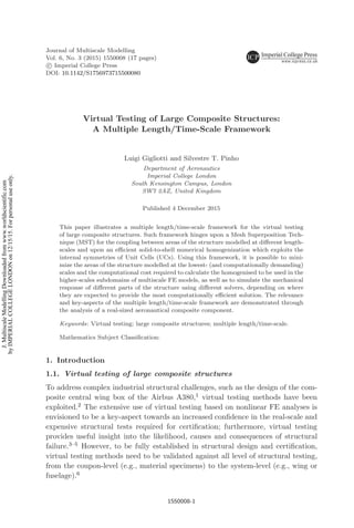
2. Multiple Length/Time Scale Framework
The multiple length/time-scale framework used in this paper, and graphically illus-
trated in Fig. 1, consists of (i) a Mesh Superposition Technique (MST)33
for the
progressive transition between subdomains discretized with finite elements of dif-
ferent physical dimension/formulation and (ii) a mathematical framework which
exploit UCs internal symmetries in the context of the direct solid-to-shell homoge-
nization of periodic structures.34
The key-aspects of the MST are:
(i) unlike conventional solid-to-shell coupling techniques based on a sudden
discretization-transition, the MST eliminates the artificial stress disturbances
at the shared boundaries between differently discretized subdomains;
(ii) using the MST, the size of the lower-scale models (the most computation-
ally demanding) can be minimized without jeopardizing the response at the
global/local transition. Therefore, compared to conventional solid-to-shell cou-
pling techniques based on a sudden discretization-transition the MST enables
a high-fidelity damage pattern prediction at a lower computational cost;
(iii) the progressive transition provided by the MST mitigates the spurious reflec-
tions of stress waves at the interfaces between differently-discretized subdo-
mains (see example in Appendix A);
1550008-4
J.MultiscaleModellingDownloadedfromwww.worldscientific.com
byIMPERIALCOLLEGELONDONon12/15/15.Forpersonaluseonly.
5. 2nd Reading
December 1, 2015 14:9 WSPC/245-JMM 1550008
Virtual Testing of Large Composite Structures
Multiple length/time scale framework for the virtual testing of large composite structures
Mesh Superposition Technique (MST)
Progressive element-type transition between differently discretized subdomains
EA
EB
Es
A
=
MST region
Es
B
Accurate damage pattern prediction Model size & CPU time reduction
0%
50%
100%
Normalized
CPU time
Sudden Tr.
Sudden Tr.
MST
MST
-60%
Model size
-23%
CPU time
Solid-to-shell homogenization exploiting symmetries
Periodic composite
structure
Unit Cells (UCs) vs
Reduced Unit Cells (rUCs)
Modelling/Analysis CPU
time reduction
a
b
B
A
0%
50%
100%
Multi
length
(-23%)
Multi
length/time
(-49%)
Model size CPU time
UC
rUC
0%
50%
100%
0%
50%
100%
rUCUC
UC rUC
-85% CPU
Modelling time
-89% CPU
Analysis time
Fig. 1. Multiple length/time-scales framework for the virtual testing of large composite com-
ponents. Such framework consists of a mesh superposition technique for coupling differently-
discretized subdomains (a) and on the exploitation of symmetries in the solid-to-shell numerical
homogenization of periodic structures.
1550008-5
J.MultiscaleModellingDownloadedfromwww.worldscientific.com
byIMPERIALCOLLEGELONDONon12/15/15.Forpersonaluseonly.
6. 2nd Reading
December 1, 2015 14:9 WSPC/245-JMM 1550008
L. Gigliotti & S. T. Pinho
(iv) the MST can be used in combination with an implicit/explicit co-simulation
technique,35,36
for a multiple time/length-scale analysis. The capability pro-
vided by the MST to minimize the size of the lower-scale models allows to
maximize the computational efficiency of the implicit/explicit co-simulation
technique; hence, in the context of a multiple length/time scale analysis, the use
of the MST for the length-scale transitions (instead of a sudden discretization-
transition) results into a significant computational cost reduction.
Regarding the exploitation of symmetries in the solid-to-shell homogenization
of periodic structure, the following points should be highlighted:
(i) the framework proposed in Ref. 34 leads to the derivation of the exact periodic
boundary conditions that apply to rUCs and enable the numerical solid-to-shell
homogenization of periodic structures, including their bending and twisting
response.
(ii) no limitations on the deformed/undeformed shape of the rUCs, as well as to
the nonlinear behavior at the lowest length-scale were made (provided there is
no localization37
);
(iii) when comparing results obtained using conventional UCs with those obtained
with rUCs, in the latter case time savings of about 90% can be achieved in the
analysis CPU time, as well as in the modelling/meshing CPU time.
3. Multiple Length/Time-Scale Simulation of a Large
Aeronautical Component
3.1. Problem description
The multiple length/time-scale framework detailed in Sec. 2 is applied to the anal-
ysis of a low-velocity impact on real-sized helicopter rotor blade. The latter is
idealized as an hollow structure with dimensions provided in Fig. 2. The profile of
the rotor blade corresponds to the NASA/Langley Whitcomb integral supercritical
3500
200
Impactor
115
1750φ 40
9 0 ◦
0 ◦
Fig. 2. Schematic (not in scale) of the helicopter rotor blade considered in this study; dimensions
are in mm.
1550008-6
J.MultiscaleModellingDownloadedfromwww.worldscientific.com
byIMPERIALCOLLEGELONDONon12/15/15.Forpersonaluseonly.
7. 2nd Reading
December 1, 2015 14:9 WSPC/245-JMM 1550008
Virtual Testing of Large Composite Structures
airfoil.38
The rotor blade is impacted with a 2.5 kg impactor of diameter equal to
40 mm and a 12 J impact energy was considered.
The profile of the rotor blade is assumed to be made of a composite sandwich
structure39,40
with pin-reinforced foam core41
; relevant geometrical and material
properties of the pin-reinforced sandwich structure can be found in Ref. 34. The
material considered for the pin-reinforcements is the carbon-epoxy T300/913.42
3.2. Multi length/time-scale FE model
3.3. Implicit and explicit FE submodels
The multiple time-scale connotation of the framework described in Sec. 2 consists
in simulating the mechanical response of different portions of the structure using
different solvers, depending on where they are expected to provide the most com-
putationally efficient solution. Generally, complex material failure, contact interac-
tions and highly nonlinear response are best analysed using FE solvers based on
explicit time-integration schemes, e.g., Abaqus/Explicit, while the elastic behavior
of light and stiff components can, more efficiently, be simulated with FE solvers
using implicit time-integration schemes, e.g., Abaqus/Standard.
Using different FE solvers implies the definition of multiple time-scales at which
the structural response is analysed: (i) an explicit/micro time-scale, character-
ized by a high number of short and relatively inexpensive time-steps and (ii) an
implicit/macro time-scale, characterized by a reduced number of larger time-steps,
due to the unconditional stability of implicit solvers.
Therefore, for the problem described in Sec. 3.1, the FE model of the rotor blade
(see Fig. 3) consists of two separate FE submodels:
(i) an explicit submodel for the area of the rotor blade surrounding the impact
location (where contact interactions and complex failure modes are expected);
within this submodel, different parts of the structure are modelled at different
length-scales as described in Sec. 3.4;
(ii) an implicit submodel for the remaining of the structure, whose deformation
remains elastic throughout the entire analysis.
In the implicit FE subdomain, the rotor blade is discretized using first-order trian-
gular shell elements (S3). The equivalent homogenised 2D behavior, i.e., the entire
ABD matrix of the pin-reinforced sandwich structure is defined exploiting the
solid-to-shell homogenization described in Sec. 2. The meshing of the entire rotor
blade required 63744 S3 elements.
In this example, the multiple length/time-scale analysis is performed exploiting
Abaqus built-in Co-Simulation Engine (CSE)15
; the simulation of the mechanical
response of the implicit and explicit submodels is performed using, respectively,
Abaqus/Explicit and Abaqus/Standard.
1550008-7
J.MultiscaleModellingDownloadedfromwww.worldscientific.com
byIMPERIALCOLLEGELONDONon12/15/15.Forpersonaluseonly.
8. 2nd Reading
December 1, 2015 14:9 WSPC/245-JMM 1550008
L. Gigliotti & S. T. Pinho
Explicit mulƟscale FE submodel Implicit FE submodel
MulƟ Ɵme/length-scale FE model
Fig. 3. Implicit/explicit submodels of a multiple length/time-scale FE model of an helicopter rotor
blade. The area surrounding the impact location is analysed using an explicit solver, to exploit its
capabilities to better handle contact interactions and complex failures modes; the response of the
remaining of the structure (the largest part) is more efficiently simulated using an implicit solver.
3.4. Multiscale explicit FE submodel
Within the explicit submodel, different parts of the structure are modelled at dif-
ferent length-scales and the coupling between them is performed using the MST.33
The size of the differently-discretized subdomains needs to be established a priori,
i.e., before the analysis, for example by exploiting analytical methods to estimate
the expected size of the damaged areas.50
For the example described in the present paper, we considered three different
regions where the structure is modelled at different length-scales (see Fig. 4):
Meso-scale subdomain Within this subdomain, the structure is modelled at
the lowest length-scale. The plies in the composite facesheets, the interfaces
between them and between the facesheets and the core, as well as the pin-
reinforcements within the core, are modelled individually.
1550008-8
J.MultiscaleModellingDownloadedfromwww.worldscientific.com
byIMPERIALCOLLEGELONDONon12/15/15.Forpersonaluseonly.
9. 2nd Reading
December 1, 2015 14:9 WSPC/245-JMM 1550008
Virtual Testing of Large Composite Structures
Explicit multiscale FE submodel
Meso-scale subdomain Macro-scale subdomain
Debonding
Core Crushing Pins ’ failureDelamination/Debonding
Meso/macro-scale subdomain
Fig. 4. Multiscale explicit FE submodel. Different areas of the structure can be modelled at
different length-scales and their coupling be performed using the MST. The mechanical response
of the structure can be correctly captured at all the length-scales of interest (both in terms of
geometrical details and failure modes), while keeping the computational cost of the analysis to a
minimum.
1550008-9
J.MultiscaleModellingDownloadedfromwww.worldscientific.com
byIMPERIALCOLLEGELONDONon12/15/15.Forpersonaluseonly.
10. 2nd Reading
December 1, 2015 14:9 WSPC/245-JMM 1550008
L. Gigliotti & S. T. Pinho
Eight-noded reduced-integration solid elements (C3D8R) with enhanced
hourglass control were used for the discretization of the composite plies,
pin-reinforcements and core layer: eight-noded cohesive elements (COH3D8)
were used to account for possible delamination (between composite plies) and
debonding (between the facesheets and the core). To simplify the meshing of the
pin-reinforced core, the pins’ finite elements were embedded within the foam
core exploiting the Embedded Element Method (EEM) available in Abaqus.
This method has been already used for modelling pin-reinforced cores44
and
textile composites.45
The discretization of the meso-scale subdomain (includ-
ing the MST transition regions) required 71896 C3D8R elements and 11520
COH3D8 elements.
The complex shape of the pin-reinforcements (i.e., misalignments, bended
ends, etc.) is also explicitly modelled. Within the meso-scale subdomain, several
failure modes are accounted for (see Fig. 4), i.e.,
(i) delamination between composite plies, as well as debonding between the
composite facesheets and the core, using multiple layers of cohesive ele-
ments with a mixed-mode bilinear traction-separation law to simulate the
softening and fracture response46,47
;
(ii) crushing of the foam core48
;
(iii) failure of the pin reinforcements49
;
Meso/Macro-scale region Within this subdomain, the composites facesheets,
the core, the interface between them, as well as the pin-reinforcements within
the core layer, are explicitly modelled.
Eight-noded reduced-integration continuum shell elements (SC8R) with
enhanced hourglass control were used for the discretization of the composite
facesheets while eight-noded reduced-integration solid elements (C3D8R) were
used for the discretization of the pin-reinforcements and of the core. As in the
meso-scale subdomain, the pins’ finite elements were embedded within the core
exploiting the EEM. The discretization of the meso-scale subdomain (includ-
ing the MST transition regions) required 181952 C3D8R elements, 54784 SC8R
elements and 11520 COH3D8 elements.
Within the meso/macro-scale subdomain, the only failure model accounted
for is the debonding between the core and the composite facesheets (see Fig. 4).
This can actually occur even at a significant distance from the impact location,
as it might initiates as a result of the stress concentrations due to the pin
reinforcements in the foam core layer.
Macro-scale region Within this subdomain, the pin-reinforced sandwich struc-
ture is discretized using reduced-integration first-order quadrangular shell ele-
ments (S4R) with enhanced hourglass control. The equivalent homogenised 2D
behavior, i.e., the corresponding entire ABD matrix of the sandwich structure
is computed exploiting the solid-to-shell homogenization described in Sec. 2.
1550008-10
J.MultiscaleModellingDownloadedfromwww.worldscientific.com
byIMPERIALCOLLEGELONDONon12/15/15.Forpersonaluseonly.
11. 2nd Reading
December 1, 2015 14:9 WSPC/245-JMM 1550008
Virtual Testing of Large Composite Structures
The discretization of the meso-scale subdomain (including the MST transition
regions) required 1516 S4R elements.
4. Discussion
The key-aspects of the multiple length/time-scale framework for the virtual testing
of large composite structures illustrated in this paper can be summarized as follows:
(i) coupling differently-discretized subdomains using the MST33
allows to mini-
mize the areas of the structure modelled at the lowest (and therefore compu-
tationally costly) length-scales. Thus, the desired level of accuracy is attained
only in selected portions of the model, which allows not to jeopardizing the
computational cost of the analysis;
(ii) the response of different portions of the structure is simulated using different
solvers, depending on where they are expected to provide the most efficient
solution;
(iii) the exploitation of symmetries in the solid-to shell homogenization34
allows
to strongly reduce the time required for the computation of equivalent
homogenised properties;
(iv) the size of the resulting multiscale FE models can be minimized without any
loss of accuracy at the lowest-scales; as a result, such FE models can be easily
handled by high-performance computing resources, as well as modern laptop
computers. As an example, the multiscale FE model of the helicopter rotor
blade discussed in Sec. 3 consisted of a total number 1291202 DOFs (410846
nodes); simulations were performed using a laptop computer with an Intel i7-
3610QM processor (2.3GHz Max Turbo Frequency), 8 CPUs and 8Gb RAM
for a total analysis time of approximately 6 hrs.
5. Conclusions
In this paper, a multiple length/time-scale framework for the virtual testing of
large composite structures is described. Its primitives and key-aspects are detailed
through the analysis of a real-sized helicopter rotor blade subjected to a low-velocity
impact.
The multiple length/time-scale framework enables a significant reduction of the
CPU time required to compute the homogenized properties used in the higher-
scales of multiscale FE models; furthermore, it allows to minimize the areas of
the structure that need to be modelled at the lowest length-scales, by oppor-
tunely coupling differently-discretized subdomains using a Mesh Superposition
Technique.
The multiple length/time-scale framework investigated in this work represents
a clear step towards the systematic and efficient virtual testing of large composite
components.
1550008-11
J.MultiscaleModellingDownloadedfromwww.worldscientific.com
byIMPERIALCOLLEGELONDONon12/15/15.Forpersonaluseonly.
12. 2nd Reading
December 1, 2015 14:9 WSPC/245-JMM 1550008
L. Gigliotti & S. T. Pinho
Acknowledgments
The funding from Airbus Operations Ltd (UK) is gratefully acknowledged.
Appendix A. Propagation of Stress Waves in Nonuniform FE
Meshes Using the Mesh Superposition Technique
A.1. Motivation
The benefits provided by the MST in avoiding the artificial stress disturbances
at the interfaces between differently-discretized subdomains are demonstrated in
Ref. 33. In this example, we aim to investigate the capability of the MST to mit-
igate the spurious reflections of stress waves at the interfaces between differently-
discretized subdomains.
A.2. FE models
An infinite bar of uniform cross-sectional area (4×4 mm2
) and made of an isotropic
elastic material (E = 60 MPa, ν = 0.25 and ρ = 1600 kg/m3
) was modelled in
Abaqus. The initial 300 mm of the bar were discretized using conventional finite ele-
ments; the infinitely long idealization is achieved using infinite elements (CIN3D8).
For the region were conventional FE models were used, three different FE models
of the infinite bar were created (see Fig. A.1):
Fully Solid (FS) Model the bar is discretized entirely using eight-noded
reduced-integration solid elements (C3D8R) with enhanced hourglass control.
Results obtained with this model are used as reference solution;
Sudden Transition (ST) Model the bar is discretized using eight-noded
reduced-integration solid elements (C3D8R) with enhanced hourglass control
for the initial 150 mm; the remaining portion, eight-noded reduced-integration
continuum shell elements (SC8R), with hourglass control and three integration
points along the element’s thickness, were used;
Fully SolidFully Solid
MST model
Sudden Transition model
Sudden
discretization-transition
MST region
Region 1 Region 2
∞
∞
∞
x
x
x
Fig. A.1. Three different FE models of the infinite bar: Fully Solid model, Sudden Transition
model and MST model.
1550008-12
J.MultiscaleModellingDownloadedfromwww.worldscientific.com
byIMPERIALCOLLEGELONDONon12/15/15.Forpersonaluseonly.
13. 2nd Reading
December 1, 2015 14:9 WSPC/245-JMM 1550008
Virtual Testing of Large Composite Structures
MST Model the sudden discretization-transition between solid (C3D8R) and con-
tinuum shell (SC8R) elements is replaced by a region where the MST is
exploited. The length of the MST region is equal to 100 mm.
In Fig. A.1, Region 1 corresponds to the portion of the bar between x = 100 mm
and x = 200 mm, while Region 2 corresponds to the portion of the bar between
x = 200 mm and x = 300 mm. Region 1 includes the sudden distretization-transition
for the ST model, and the entire MST region for the MST model.
A.3. Stress-wave propagation analysis
The applied displacement and boundary conditions considered are shown in
Fig. A.2. The applied displacement consists of a finite discrete impulse defined
using Fourier series as
u(z, t) =
u(z)
κ
κ
i=1
sin(2πifmint), (A.1)
where κ = fmax
fmin
is the number of terms in the Fourier series, u(z) is the amplitude
of the applied displacement as a function of the out-of-plane coordinate, and fmin
and fmax are, respectively, the minimum and maximum frequency of interest.
In Fig. A.3, the evolution of the applied displacement as a function of time (t)
(Fig. A.3(a)) and of the z-coordinate (Fig. A.3(b)) is shown.
Simulations were performed using Abaqus/Standard. The analysis time-step
was chosen so that the Courant-Friedrichs-Lewy condition51
(CFL) is fulfilled. The
essence of the CFL condition is that, given a certain wave travelling across a discrete
spatial grid, its amplitude can be correctly computed at fixed time steps of constant
duration, only if the latter is smaller than the time needed for the wave to travel
between two consecutive nodes of the spatial grid. In the simplified scenario of 1D
wave propagation, the CFL condition can be expressed in terms of the Courant
4 mm
4 mm
y
z
u(z , t)
y
x
300 mm, 300 elements
∞
Conventional Finite Elements
Fig. A.2. Applied displacement and boundary conditions for the stress-wave propagation study.
1550008-13
J.MultiscaleModellingDownloadedfromwww.worldscientific.com
byIMPERIALCOLLEGELONDONon12/15/15.Forpersonaluseonly.
14. 2nd Reading
December 1, 2015 14:9 WSPC/245-JMM 1550008
L. Gigliotti & S. T. Pinho
(a) Normalized amplitude of the applied (b) Amplitude of the applied displacement
displacement as a function of time. as a function of the z-coordinate.
Fig. A.3. Time and space evolution of the applied displacement u(z, t). The resulting applied
displacement is a finite discrete impulse with variable amplitude along the through-the-thickness
direction.
number C as
C =
c∆tmax
≤ Cmax, (A.2)
where c is the dilatational wave speed and is the characteristic length of the
spatial grid. A value of Cmax = 1 is usually tolerated when implicit solvers are used.
Nevertheless, a maximum time-step of 20 ns (C ≈0.122) was chosen for the analysis
presented here.
A.4. Results and discussion
Fig. A.4 shows the internal energy U of Region 1 and Region 2 (see Fig. A.1) as
a function of time. Such internal energy corresponds to the energy carried by the
stress waves travelling along the bar.
The stress waves enter into Region 1 at t ≈ 0.014 ms when the energy content
of the latter starts increasing (see Fig. A.4(a)). At t ≈ 0.029 ms, the stress waves
travel from Region 1 into Region 2 (the energy content of Region 1 starts decreasing
and, correspondingly, that of Region 2 starts increasing).
However, after t ≈ 0.029 ms the energy content of Region 1 computed with
the ST model is higher than that computed with both the FS and MST model; a
specular behavior is associated to the energy content of Region 2. This evidence
indicates that part of the stress waves travelling along the bar has been reflected
by the sudden discretization-transition included in the ST model.
1550008-14
J.MultiscaleModellingDownloadedfromwww.worldscientific.com
byIMPERIALCOLLEGELONDONon12/15/15.Forpersonaluseonly.
15. 2nd Reading
December 1, 2015 14:9 WSPC/245-JMM 1550008
Virtual Testing of Large Composite Structures
0
10
20
30
0 0.02 0.04
SOL
ST
MST
U [J]
t [ms]
FS
ST
MST
0
10
20
30
0 0.02 0.04
SOL
ST
MST
U [J]
t [ms]
FS
ST
MST
(a) Region 1 (b) Region 2
Fig. A.4. Time history of the internal energy of Region 1 (a) and Region 2 (b) associated with the
propagation of the travelling stress waves along the infinite bar.
When compared to the reference solution obtained with the FS model, an energy
loss of approximately 17 % due to stress-wave reflections is observed when using the
ST model. On the other hand, when using the MST for the progressive transition
between the two differently-discretized subdomains, the energy loss associated to
stress-wave reflections is almost completely eliminated (approximately 99% reduc-
tion if compared to the ST model).
The results presented in this section demonstrate that the MST33
allows to
avoid, in addition to the artificial stress disturbances, also the spurious reflections
of stress waves at the interfaces between differently-discretized subdomains.
References
1. J. Pora, Composite Materials in the Airbus A380 — From History to Future — Proc.
13th Int. Conf. Compos. Mater. (2001).
2. M. Ostergaard, A. R. Ibbotson, O. Le Roux and A. M. Prior, Aeronaut. J. 1 (2011)
83–103.
3. J. F. Imbert, Airbus, Challenges in Aircraft Structure Analysis — ESA/NAFEMS
Seminar on Engineering Quality, Verification and Validation, Noordwijk (2007).
4. A. Prior, Dassault Syst´emes, Nonlinear Simulation of Large Scale Aircraft Struc-
tures — Implications for Certification Methodology and High-Performance Computing
Infrastructure — NAFEMS World Congress (2009).
5. A. Prior, Dassault Syst´emes, Simulating Damage and Failure in Aircraft Structures —
RAeS Conference: Challenges for the Next Generation-Concept to Disposal (2008).
6. T. Brown, Airbus, Working to Meet the Challenges of Ext Generation Composite Wing
Structural Design — RAeS Conference: Challenges for the Next Generation-Concept
to Disposal (2008).
1550008-15
J.MultiscaleModellingDownloadedfromwww.worldscientific.com
byIMPERIALCOLLEGELONDONon12/15/15.Forpersonaluseonly.
16. 2nd Reading
December 1, 2015 14:9 WSPC/245-JMM 1550008
L. Gigliotti & S. T. Pinho
7. European Aviation Safety Agency, Certification Specifications for Large Aeroplanes
CS-25 Amendement 5 (2008).
8. R. W. McCune, C. G. Armstrong and D. J. Robinson, Int. J. Numer. Methods Eng.
49 (2000) 725–750.
9. C. G. D´avila, Comput. Syst. Eng. 5 (1994) 193–202.
10. D. M. Thompson and O. H. Griffin, Two-dimensional/Three-dimensional Global/Local
Finite Element Analysis of Composite Laminates — Proc. 4th Ann. American Soc.
Composite Conf., 4th Tech. Conf., Technomic Publishing, Lancaster, PA (1989) 234–
243.
11. Z. P. Baˇzant, Comput. Methods Appl. Mech. Eng. 16 (1978) 91–100.
12. Z. Celep and D. Turhan, J. Sound Vib. 116 (1987) 15–23.
13. K. Shim, D. Monaghan and C. Armstrong, Eng. Comput. 18 (2002) 241–252.
14. N. Osawa, K. Hashimoto, J. Sawamura, T. Nakai and S. Suzuki, Mar. Struct.
20 (2007) 143–163.
15. Dassault Syst´emes Simulia Corp., ABAQUS 6.12 User’s Manual (2012).
16. J. Reinoso, A. B´azquez, A. Estefani, F. Par´ıs, J. Canas, E. Ar´evalo and F. Cruz,
Compos. Part B 43 (2012) 1929–1942.
17. J. Reinoso, A. B´azquez, A. Estefani, F. Par´ıs, J. Canas and E. Ar´evalo, Compos.
Struct. 101 (2013) 274–289.
18. R. Krueger and T. K. O’Brien, Compos. Part A 32 (2001) 25–44.
19. R. Krueger, J. Ratcliffe and P. J. Minguet, NASA/CR-2007-214879 NIA Report No.
2007–07 (2007).
20. R. Krueger and P. J. Minguet, Compos. Struct. 81 (2007) 41–59.
21. R. Krueger, J. C. Ratcliffe and P. J. Minguet, Compos. Sci. Tech. 69 (2009) 2352–
2362.
22. A. Gusev, J. Mech. Phys. Solids 45 (1997) 1449–1459.
23. I. Gitman, H. Askes and L. Sluys, Eng. Fracture Mech. 74 (2007) 2518–2534.
24. C. Sun and R. Vaidya, Compos. Sci. Technol. 56 (1996) 171–179.
25. Z. Xia, Y. Zhang and F. Ellyin, Int. J. Solids Struct. 40 (2003) 1907–1921.
26. Z. Xia, C. Zhou, Q. Yong and X. Wang, Int. J. Solids Struct. 43 (2006) 266–278.
27. S. Li, Compos. Sci. Technol. 68 (2008) 1962–1974.
28. S. Li, Compos. Part A 32 (2001) 815–826.
29. S. Li and A. Wongsto, Mech. Mater. 36 (2004) 543–572.
30. J. Whitcomb, C. Chapman and X. Tang, J. Compos. Mater. 34 (2000) 724–747.
31. N. V. de Carvalho, S. T. Pinho and P. Robinson, Compos. Sci. Technol. 71 (2011)
969–979.
32. N. V. de Carvalho, S. T. Pinho and P. Robinson, arXiv:1012.3133v1 (2010) 1–18.
33. L. Gigliotti and S. T. Pinho, Compos. Struct. 121 (2015) 395–405.
34. L. Gigliotti and S. T. Pinho, Compos. Struct. 132 (2015) 995–1005.
35. A. Gravouil and A. Combescure, Int. J. Numer. Methods Eng. 50 (2001) 199–225.
36. A. Combescure and A. Gravouil, Comput. Methods Appl. Mech. Eng. 191 (2002)
1129–1157.
37. Z. P. Baˇzant, Int. J. Multiscale Comput. Eng. 8 (2010).
38. R. T. Whitcomb, Review of NASA Supercritical Airfoils —Proc. 9th Congr. Int. Coun-
cil Aeron. Sci., Haifa, Israel (1974).
39. G. Endres, Innovative Sandwich Constructions for Aircraft Application — Proc. 9th
Int. Conf. Sandwich Struct., Pasadena, CA (2010).
40. L. Gigliotti and S. T. Pinho, On the Monotonic and Cyclic Compressive Response of
Polymeric Foam Cores with TFC-Reinforcements, In preparation (2016).
1550008-16
J.MultiscaleModellingDownloadedfromwww.worldscientific.com
byIMPERIALCOLLEGELONDONon12/15/15.Forpersonaluseonly.
17. 2nd Reading
December 1, 2015 14:9 WSPC/245-JMM 1550008
Virtual Testing of Large Composite Structures
41. L. Gigliotti and S. T. Pinho, Prediction of the Post-Crushing Compressive Response
of Progressively Crushable Sandwich Foam Cores, Compos. Part A, Accepted for pub-
lication (2016).
42. S. T. Pinho, L. Iannucci and P. Robinson, Compos. Part A 37 (2006) 766–777.
43. HexFlow, RTM6-2 - Product Information (2010).
44. T. Liu, Z. Deng and T. Lu, Int. J. Solids Struct. 45 (2008) 5127–5151.
45. S. Tabatabaei, S. Lomov and I. Verpoest, Compos. Struct. 107 (2014) 436–446.
46. G. Alfano and M. A. Crisfield, Int. J. Numer. Methods Eng. 50 (2001) 1701–1736.
47. Q. Yang and B. Cox, Int. J. Fract. 133 (2005) 107–137.
48. V. S. Deshpande and N. A. Fleck, J. Mech. Phys. Solids 48 (2000) 1253–1283.
49. Z. Hashin, J. App. Mech. 47 (1980) 329–334.
50. R. Olsson and T. B. Block, Compos. Struct. 125 (2015) 81–87.
51. C. Richard, F. Kurt and L. Hans, IBM J. Res. Dev. 11 (1967) 215–234.
1550008-17
J.MultiscaleModellingDownloadedfromwww.worldscientific.com
byIMPERIALCOLLEGELONDONon12/15/15.Forpersonaluseonly.