
Recommended
Recommended
More Related Content
Similar to Bonfiglioli kf series precision right angle gearbox
Similar to Bonfiglioli kf series precision right angle gearbox (20)
More from Lance Shi NER GROUP
More from Lance Shi NER GROUP (20)
Recently uploaded
Recently uploaded (20)
Bonfiglioli kf series precision right angle gearbox
- 5. 1 Revisions Refer to page 22 for the catalogue revision index. Visit www.bonfiglioli.com to search for catalogues with up-to-date revisions. SUMMARY 1 General information ............................................................................................................................................................... 3 1.1 Symbols, units and definitions ........................................................................................................................................ 3 1.2 Selecting the gear unit .................................................................................................................................................... 4 2 Features of KR series ............................................................................................................................................................ 6 2.1 Versions .......................................................................................................................................................................... 7 2.2 Mounting positions .......................................................................................................................................................... 7 2.3 Coordinated shaft rotation ............................................................................................................................................... 7 3 Ordering code ........................................................................................................................................................................ 8 4 Technical specifications ....................................................................................................................................................... 9 5 Mass moment of inertia ....................................................................................................................................................... 10 5.1 KR 010...KR 040 with standard ball bearings ............................................................................................................... 10 5.2 KR 020...KR 040 with taper roller bearings (HDB option) ............................................................................................. 11 6 Dimensions .......................................................................................................................................................................... 12 KR 010 .......................................................................................................................................................................... 12 KR 020 .......................................................................................................................................................................... 14 KR 030 .......................................................................................................................................................................... 16 KR 040 .......................................................................................................................................................................... 18 6.1 Gearbox without motor adapter - FM ............................................................................................................................ 20 6.2 Machine shaft ............................................................................................................................................................... 21
- 6. 3 term u.m. definition A2 [N] Thrust force on output shaft A2 EQU [N] Equivalent thrust force applying on output shaft A2 MAX [N] Maximum thrust force applying on output shaft R2 [N] Radial force on output shaft R2 EQU [N] Equivalent radial force applying on output shaft R2 MAX [N] Maximum radial force applying on output shaft ED [min] Loading time ED% [%] Loading time % L10h TARGET [h] Output shaft bearings’ desired basic rating life M1 PEAK [Nm] Maximum input torque (usually motor) M2(1) ... M2(n) [Nm] Output torque at each of the time periods t1 ... tn M2 EQU [Nm] Equivalent output torque M2 MAX [Nm] Maximum output torque in case of emergency MT2 EQU [Nm] Equivalent tilting moment applying on output shaft MT2 MAX [Nm] Maximum tilting moment applying on output shaft n2 [min-1] Output speed n2(1) ... n2(n) [min-1] Output speed based on the time periods t1 ... tn n2 EQU [min-1] Equivalent output speed n2 MAX [min-1] Maximum output speed T [C°] Ambient temperature t1 ... tn [s] Time periods of motion t∑ [s] Cycle duration including pause Z [1/h] Cycle number per hour Values depending on the APPLICATION term u.m. definition A2 3 max [N] Admissible thrust force on output shaft A2'max [N] Thrust force acting simultaneously with the rated radial force R1 max [N] Admissible radial force at midpoint of input shaft R2 3 max [N] Admissible radial force at midpoint of output shaft CB [Nm] Constant for bearing's lifetime calculation Ct Torsional stiffness fn — Speed factor fz — Cycle factor fT — Temperature adjusting factor i — Gearbox ratio JG [kgcm²] Mass moment of inertia of the gearhead Kn — Speed constant L10h [h] Bearings’ basic rating life LZ [mm] Factor for bearing's lifetime calculation Ma 2 [Nm] Maximum acceleration output torque Mn 2 [Nm] Rated output torque Mp 2 [Nm] Emergency stop output torque MT2 max [Nm] Maximum tilting moment applying on output shaft n1 max [min-1] Maximum momentary input speed. The speed the unit can be driven at occasionally and in non-repetitive conditions For cycle duty type S5, it cannot be applied continuously for more than 30 seconds p — Bearing lifetime exponent η [%] Gear efficiency ϕR [arcmin] Reduced backlash is calculated in static conditions and with the application of a torque equal to 2% of the gear unit rated torque ϕS [arcmin] Standard backlash is calculated in static conditions and with the application of a torque equal to 2% of the gear unit rated torque Values depending on the GEAR DRIVE SELECTION 1 GENERAL INFORMATION 1.1 SYMBOLS, UNITS AND DEFINITIONS
- 7. 4 1.2 SELECTING THE GEAR UNIT fn - speed factor 0.5 1 1.5 2 2.5 3 10.50 fn Kn n2 EQU · i Kn - speed constant i KR 010 KR 020 KR 030 KR 040 1 1200 1200 1000 800 2 2400 2400 2000 1600 5 3000 3000 2800 2500 (a) Ratio i — n2 n1 i = (b) Equivalent output torque M2 EQU [Nm] 3 M2EQU tnn2(n)...t1n2(1) ++ + + 3 ...M2(1)t1n2(1) 3 M2(n)tnn2(n) = (c) Equivalent output speed n2 EQU [min-1] t n2EQU t2n2(2)t1n2(1) tnn2(n)... ++ + = (d) Speed factor fn — If Kn ≥ 1 fn = 1 n2 EQU i If Kn < 1 fn = n2 EQU i Obtain from diagram (e) Loading time % ED% [%] ED% = 100 tn...t2t1 +++ t Loading time ED [min] ED = tn...t2t1 +++ (f) Cycle number per hour Z [1/h] t 3600 =Z (g) Cycle factor fz — Z fz Z ≤ 1000 1.00 1000 < Z ≤ 1500 1.25 1500 < Z ≤ 2500 1.50 2500 < Z ≤ 4000 1.75 4000 < Z ≤ 6000 2.00 Z > 6000 contact us (h) Temperature adjusting factor fT — If T ≤ 30°C fT = 1 If T > 30°C 1fT C100° C30T° += (i) Maximum input torque M1 PEAK [Nm] a) maximum possible application torque b) limited motor torque by inverter c) maximum motor torque
- 8. 5 Z 1000 Define M1 PEAK M1 PEAK · i · Ma 2 YES NO NO NO YES YES YES YES NO M2 MAX Mp 2 NO NO YES n2 MAX · i n1 max M2 EQU · fn Mn 2 Define n2 EQU Define M2 EQU Define fn Define fZ (a) (b) (c) (d) (e) (g) (h) (i) (f) Define fT M1 PEAK · i · fZ · fT · Ma 2 Define M1 PEAK S5 cycle duty Select gear unit S1 cycle duty Select a bigger unit Select a bigger unit Select a bigger unit Select a bigger unit Check the external forces on output shaft Select a smaller ratio ED% 60% and ED 20 min ED% 60% or ED 20 min Estimate ratio i Load diagram M2: Output torque Speed diagram n2: Output speed 0 0 t1 t2 t3 t4 [s] [s] ED M2(1) M2(2) n2(2) n2(1) M2(3) n2(1) = n2(3) = 0.5 • n2(2)n2(3)
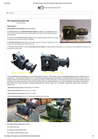
- 9. 6 2 FEATURES OF KR SERIES Bevel helical units type KR, manufactured under the most stringent quality specifications, are designed for dynamic and accurate appli- cations where light weight and space effectiveness are a factor. Many options can be selected from the catalogue as far as motor adapters and output shaft configurations that facilitate the installation on the driven equipment. • Available in one only backlash option (ϕS = 8’) • Single reduction: ratios i = 1, 2, 5 • Radial ball bearings (SB) are of standard supply, while taper roller bearings (HB) can be optionally specified for particularly demanding loading conditions • Degree of protection IP65 • Oil seals from Viton® compound as standard • Max. noise level LP ≤ 70 dB(A) @ n1 = 3000 min-1 • Units are factory charged with synthetic lubricant suitable for operation at ambient temperatures in the range 0°…40°C. The lubricant quantity is affected by mounting position, that therefore will have to be specified at the time of ordering. In the absence of contamination lubricant does not require periodical changes. The type of lubricant, whether grease or oil, depends on type of duty, as charted below: duty KR 010 ... KR 040 S1 (continuous) synthetic oil viscosity ISO VG 220 S5 (intermittent) NLGI grease consistency 00 Distribution of nominal torque Mn2 [Nm] [i] 1 2 5 KR 010 10 7 3 KR 020 24 15 10 KR 030 55 37 22 KR 040 120 85 45 Available motor shaft bores 6 8 97 6.35 9.52 12.7 15.875 19.05 10 1211 14 15 16 1917 22 24 28 KR 010 KR 020 KR 030 KR 040 ø [mm]
- 10. 7 2.1 VERSIONS Parallel shaft LP LPF LD LDF single extension single extension + flange double extension double extension + flange Hollow shaft H HF S SF keyed (KR 030...KR 040) keyed shaft + flange (KR 030...KR 040) with shrink disc with shrink disc + flange U VA 2.2 MOUNTING POSITIONS 2.3 COORDINATED SHAFT ROTATION
- 11. 8 3 ORDERING CODE KR 030 1 STD LP 60A CD 14 S1 U SB 7 12 20 14 16 18 12 14 16 18 OUTPUT SHAFT BEARINGS standard reinforced (KR 020 ... KR 040) SB HB BACKLASH ϕS = 8'STD DUTY continuous duty intermittent duty S1 S5 MOTOR COUPLING clamping deviceCD INPUT SECTION motor adapter without motor adapter 25 ... 180 FM SERIES KR GEAR RATIO 1 52 7 VERSION Parallel shaft: Hollow shaft: (KR 030 ... KR 040) (KR 030 ... KR 040) LP H LD S LDF SF LPF HF MOUNTING POSITION U VA FRAME SIZE 010 030020 040 INPUT SHAFT BORE
- 12. 9 4 TECHNICAL SPECIFICATIONS ...LP ...LD A3 maxA2 max R3 max R2 max R2 max A2 max A2' max R3 max A3 max A3' max [N] [N] [N] [N] [N] [N] KR 010 SB 1000 — 200 500 — 100 KR 020 SB 1500 — 300 750 — 150 HB 3000 1500 600 3000 1500 600 KR 030 SB 2000 — 400 1000 — 200 HB 4000 2000 800 4000 2000 800 KR 040 SB 3000 — 600 1500 — 300 HB 5500 2750 1100 5500 2750 1100 KR 010 Mn 2 Ma 2 Mp 2 n1 max ϕS η [Nm] [Nm] [Nm] [min-1] [arcmin] % i = 1 10 14 20 4000 8’ 97i = 2 7 10 15 5000 i = 5 3 4 6 5000 KR 030 Mn 2 Ma 2 Mp 2 n1 max ϕS η [Nm] [Nm] [Nm] [min-1] [arcmin] % i = 1 55 75 110 3500 8’ 97i = 2 37 52 75 4500 i = 5 22 29 45 4500 KR 020 Mn 2 Ma 2 Mp 2 n1 max ϕS η [Nm] [Nm] [Nm] [min-1] [arcmin] % i = 1 24 35 50 4000 8’ 97i = 2 15 21 30 5000 i = 5 10 13 20 5000 KR 040 Mn 2 Ma 2 Mp 2 n1 max ϕS η [Nm] [Nm] [Nm] [min-1] [arcmin] % i = 1 120 170 240 3500 8’ 97i = 2 85 120 170 4500 i = 5 45 60 90 4500
- 13. 10 5 MASS MOMENT OF INERTIA 5.1 KR 010...KR 040 with standard ball bearings - SB KR 010 JG [kgcm2] SB 6 ≤ D ≤ 9.52 10 ≤ D ≤ 14 i = 1 S, SF 0.52 0.52 LP, LPF 0.38 0.38 LD, LDF 0.39 0.39 i = 2 S, SF 0.27 0.29 LP, LPF 0.24 0.25 LD, LDF 0.24 0.25 i = 5 S, SF 0.20 0.21 LP, LPF 0.19 0.21 LD, LDF 0.19 0.21 KR 030 JG [kgcm2] SB 11 ≤ D ≤ 12.7 14 ≤ D ≤ 19 22 ≤ D ≤ 24 i = 1 H, HF 4.37 4.45 4.64 S, SF 5.00 5.08 5.27 LP, LPF 4.70 4.78 4.97 LD, LDF 4.63 4.71 4.90 i = 2 H, HF 2.04 2.12 2.31 S, SF 2.20 2.28 2.47 LP, LPF 2.12 2.20 2.39 LD, LDF 2.11 2.19 2.37 i = 5 H, HF 1.47 1.55 1.74 S, SF 1.50 1.57 1.76 LP, LPF 1.48 1.56 1.75 LD, LDF 1.48 1.56 1.75 KR 040 JG [kgcm2] SB 14 ≤ D ≤ 19 22 ≤ D ≤ 24 D = 28 i = 1 H, HF 17.19 17.37 17.77 S, SF 20.46 20.65 21.05 LP, LPF 18.21 18.40 18.80 LD, LDF 18.90 19.08 19.48 i = 2 H, HF 4.47 4.65 5.06 S, SF 5.29 5.47 5.87 LP, LPF 4.73 4.91 5.31 LD, LDF 4.90 5.08 5.48 i = 5 H, HF 5.23 5.42 5.82 S, SF 5.36 5.55 5.95 LP, LPF 5.27 5.46 5.86 LD, LDF 5.30 5.49 5.89 KR 020 JG [kgcm2] SB 8 ≤ D ≤ 12.7 14 ≤ D ≤ 19.05 i = 1 S, SF 1.61 1.80 LP, LPF 1.34 1.52 LD, LDF 1.37 1.55 i = 2 S, SF 0.86 1.05 LP, LPF 0.80 0.98 LD, LDF 0.80 0.99 i = 5 S, SF 0.66 0.84 LP, LPF 0.64 0.83 LD, LDF 0.65 0.83
- 14. 11 5.2 KR 020...KR 040 with taper roller bearings - HB KR 030 JG [kgcm2] HB 11 ≤ D ≤ 12.7 14 ≤ D ≤ 19 22 ≤ D ≤ 24 i = 1 H, HF 5.48 5.56 5.75 S, SF 6.11 6.19 6.38 LP, LPF 5.81 5.89 6.08 LD, LDF 5.74 5.82 6.01 i = 2 H, HF 2.92 3.00 3.19 S, SF 3.08 3.16 3.35 LP, LPF 3.01 3.09 3.27 LD, LDF 2.99 3.07 3.26 i = 5 H, HF 1.51 1.59 1.78 S, SF 1.54 1.62 1.81 LP, LPF 1.53 1.61 1.80 LD, LDF 1.53 1.60 1.79 KR 040 JG [kgcm2] HB 14 ≤ D ≤ 19 22 ≤ D ≤ 24 D = 28 i = 1 H, HF 18.82 19.01 19.41 S, SF 22.10 22.28 22.69 LP, LPF 19.85 20.04 20.44 LD, LDF 20.53 20.72 21.12 i = 2 H, HF 4.88 5.06 5.47 S, SF 5.70 6.28 6.28 LP, LPF 5.13 5.72 5.72 LD, LDF 5.31 5.89 5.89 i = 5 H, HF 5.30 5.48 5.89 S, SF 5.43 6.02 6.02 LP, LPF 5.34 5.93 5.93 LD, LDF 5.37 5.95 5.95 KR 020 JG [kgcm2] HB 8 ≤ D ≤ 12.7 14 ≤ D ≤ 19.05 i = 1 S, SF 1.87 2.06 LP, LPF 1.60 1.78 LD, LDF 1.62 1.81 i = 2 S, SF 0.93 1.12 LP, LPF 0.86 1.05 LD, LDF 0.87 1.05 i = 5 S, SF 0.67 0.85 LP, LPF 0.66 0.84 LD, LDF 0.66 0.84
- 15. 12 KR 010 6 DIMENSIONS 56 61 86 N5 56 N3 ØDF7 30.530.5 ØN N4 N2 N1 N1 min N1 max N 4 56 17 34 17 34 12 19 38 66 19 38 12 M 4x8 M 4x8 1.2 N N1 N2 N3 N4 N5 Lmax min max 25AH 6 6.35 7 8 9 9.52 – – – – – 25 39 56 65 3.5 4.5 25 25 26AH 6 6.35 7 8 9 9.52 – – – – – 26 39 56 28AH 6 6.35 7 8 9 9.52 – – – – – 28 39 56 30AH 6 6.35 7 8 9 9.52 – – – – – 30 39 56 32AH 6 6.35 7 8 9 9.52 – – – – – 32 39 56 34AH 6 6.35 7 8 9 9.52 – – – – – 34 40 56 36AH 6 6.35 7 8 9 9.52 – – – – – 36 42 56 39AH 6 6.35 7 8 9 9.52 – – – – – 39 45 56 40AH 6 6.35 7 8 9 9.52 – – – – – 40 46 56 38B 6 6.35 7 8 9 9.52 10 11 12 12.7 – 38.1 66.6 60 3 M4x10 18 25 40B 6 6.35 7 8 9 9.52 10 11 12 12.7 – 40 63 60 3 M4x10 18 25 50A 6 6.35 7 8 9 9.52 10 11 12 12.7 – 50 60 60 3 M4x10 18 25 50B 6 6.35 7 8 9 9.52 10 11 12 12.7 14 50 65 60 3 M5x12 23 30 50BH 6 6.35 7 8 9 9.52 10 11 12 12.7 14 50 65 65 3 5.5 25 32 50C 6 6.35 7 8 9 9.52 10 11 12 12.7 14 50 70 60 3 M4x10 23 30 55MH 6 6.35 7 8 9 9.52 10 11 12 12.7 – 55 80 65 2 5.5 16 23 60A 6 6.35 7 8 9 9.52 10 11 12 12.7 – 60 75 63 3 M5x12 18 25 60A1 6 6.35 7 8 9 9.52 10 11 12 12.7 14 60 75 63 3 M5x12 23 30 60B 6 6.35 7 8 9 9.52 10 11 12 12.7 14 60 85 75 3 M5x12 23 30 60C 6 6.35 7 8 9 9.52 10 11 12 12.7 14 60 90 75 3 M5x12 23 30 70A 6 6.35 7 8 9 9.52 10 11 12 12.7 14 70 85 75 3 M6x15 23 30 70B 6 6.35 7 8 9 9.52 10 11 12 12.7 14 70 90 75 3 M5x12 23 30 73A 6 6.35 7 8 9 9.52 10 11 12 12.7 14 73 98.4 85 3 M5x12 25 32 80A 6 6.35 7 8 9 9.52 10 11 12 12.7 14 80 100 85 3 M6x15 23 30
- 16. 13 70 15 G7Ø11 15 11 15 100 H7Ø10 1 65 Ø44 44 109 h94 M4x10 k612 13.5 2.5 20 2.5 251 44 1 44 25 20 138 h9420 2.5 251 4443 112 13.5 M4x10 k612 Ø45g6 6 3.5 44 1 Ø45g6 6 3.5 44 1 56 45° 56 5.5 Ø 64 56 45° 56 5.5 Ø 64 Ø45g6 6 3.5 44 0.5 56 45° 56 5.5 Ø 64 Ø38 M5 3.5 Nm KR 010... S KR 010... LP KR 010... LPF KR 010... SF KR 010... LD KR 010... LDF KR 010
- 17. 14 KR 020 104 N5 61 N3 ØDF7 3838 ØN 69 N4 45° N1 N2 69 76 18.5 37 18.5 37 13 25.5 51 6.56.5 25.5 51 13M 5x8 M 5x8 2.6 N N1 N2 N3 N4 N5 Lmax 40B1 8 9 9.52 11 12 12.7 14 – – – – – 40 63 80 4 M4x10 34 40 45A 8 9 9.52 11 12 12.7 – – – – – – 45 63 80 4 M4x10 34 40 50B1 8 9 9.52 11 12 12.7 14 – – – – – 50 65 80 4 M5x16 34 40 50BH1 8 9 9.52 11 12 12.7 14 – – – – – 50 65 80 4 5.5 34 40 50C1 8 9 9.52 11 12 12.7 14 – – – – – 50 70 80 4 M4x10 34 40 50D 8 9 9.52 11 12 12.7 14 – – – – – 50 95 80 4 M6x10 34 40 55A 8 9 9.52 11 12 12.7 14 15.875 16 17 19 19.05 55.5 125.7 105 4 M6x16 34 40 60A2 8 9 9.52 11 12 12.7 14 – – – – – 60 75 80 4 M5x16 34 40 60AH2 8 9 9.52 11 12 12.7 14 – – – – – 60 75 90 4 5.5 34 40 60B1 8 9 9.52 11 12 12.7 14 15.875 16 – – – 60 85 80 4 M5x16 34 40 60C1 8 9 9.52 11 12 12.7 14 15.875 16 – – – 60 90 80 4 M5x16 34 40 70A1 8 9 9.52 11 12 12.7 14 15.875 16 17 19 19.05 70 85 80 4 M6x20 34 40 70AH1 8 9 9.52 11 12 12.7 14 15.875 16 17 19 19.05 70 85 90 4 6.5 34 40 70B1 8 9 9.52 11 12 12.7 14 15.875 16 17 19 19.05 70 90 80 4 M5x16 34 40 73A1 8 9 9.52 11 12 12.7 14 – – – – – 73 98.4 85 4 M5x16 34 40 80A1 8 9 9.52 11 12 12.7 14 15.875 16 17 19 19.05 80 100 90 4 M6x16 34 40 95A 8 9 9.52 11 12 12.7 14 15.875 16 17 19 19.05 95 115 100 4 M8x20 34 40 95B 8 9 9.52 11 12 12.7 14 15.875 16 17 19 19.05 95 130 115 4 M8x20 34 40 110A 8 9 9.52 11 12 12.7 14 15.875 16 17 19 19.05 110 130 115 4 M8x20 34 40 110B 8 9 9.52 11 12 12.7 14 15.875 16 17 19 19.05 110 145 120 6.5 M8x20 44 50 110B1 8 9 9.52 11 12 12.7 14 15.875 16 17 19 19.05 110 145 120 6.5 M8x20 54 60
- 18. 15 83 20 G7Ø16 20 123 1.5 76.5 Ø52 53.5 130 h95 M5x12.5 k616 17 1.5 25 1.5 281.5 53.5 1.5 53.5 28 25 163 h9525 1.5 281.5 53.552 133.5 17 M5x12.5 k616 Ø60g6 6 5 53.5 2 Ø60g6 6 5 53.5 2 62 45° 62 5.5 Ø 68 62 45° 62 5.5 Ø 68 Ø60g6 6 5 53.5 2 62 45° 62 5.5 Ø 68 15 19 H7Ø15 Ø44 M5 4 Nm KR 020... S KR 020... SF KR 020... LP KR 020... LD KR 020... LDF KR 020... LPF KR 020
- 19. 16 KR 030 126 N5 81 N3 ØDF7 44.544.5 ØN 82 N4 45° N1 N2 82 89 23.5 47 23.5 47 22 38 76 1111 38 76 22 M 5x8 M 5x8 4.6 N N1 N2 N3 N4 N5 Lmax 50D 11 12 12.7 14 15 15.875 16 19 – – 50 95 100 5 M6x14 28 40 55A 11 12 12.7 14 15 15.875 16 19 – – 55.5 125.7 105 5 M6x16 28 40 60A2 11 12 12.7 14 15 15.875 16 19 – – 60 75 100 5 M5x14 28 40 60AH2 11 12 12.7 14 15 15.875 16 19 – – 60 75 100 5 6.5 33 40 60B1 11 12 12.7 14 15 15.875 16 19 – – 60 85 100 6.5 M5x14 28 40 70A1 11 12 12.7 14 15 15.875 16 19 – – 70 85 100 5 M6x14 28 40 70AH1 11 12 12.7 14 15 15.875 16 19 – – 70 85 100 5 6 33 40 70B1 11 12 12.7 14 15 15.875 16 19 – – 70 90 100 5 M5x12 28 40 80A1 11 12 12.7 14 15 15.875 16 19 – – 80 100 100 5 M6x16 28 40 80AH1 11 12 12.7 14 15 15.875 16 19 – – 80 100 100 5 6.5 28 40 95A 11 12 12.7 14 15 15.875 16 19 – – 95 115 100 5 M8x18 28 40 95A1 11 12 12.7 14 15 15.875 16 19 22 24 95 115 100 5 M8x18 38 50 95B 11 12 12.7 14 15 15.875 16 19 – – 95 130 115 5 M8x18 28 40 110A 11 12 12.7 14 15 15.875 16 19 – – 110 130 115 5 M8x18 28 40 110A1 11 12 12.7 14 15 15.875 16 19 22 24 110 130 115 6.5 M8x20 38 50 110B 11 12 12.7 14 15 15.875 16 19 22 24 110 145 120 6.5 M8x20 38 50 110B1 11 12 12.7 14 15 15.875 16 19 22 24 110 145 120 6.5 M8x20 48 60 130A 11 12 12.7 14 15 15.875 16 19 22 24 130 165 140 6.5 M10x20 38 50 130A1 11 12 12.7 14 15 15.875 16 19 22 24 130 165 140 6.5 M10x25 48 60
- 20. 17 h9632 2 362 6563 164 24.5 M8x19 k622 Ø70g6 7 5 65 2 76 45° 76 6.5 Ø 85 h96 M8x19 k622 24.5 2 32 2 362 65 2 65 36 32 202 Ø70g6 7 5 65 2 76 45° 76 6.5 Ø 85 20.8 6 G718 20 130 20 65 Ø70g6 7 65 5 2 76 45° 76 6.5 Ø 85 H8 100 25 G7Ø22 25 150 2 95 Ø64 65 160 Ø70g6 7 5 65 2 76 45° 76 6.5 Ø 85 19 23 H7Ø20 Ø50 M5 5 Nm KR 030... H KR 030... HF KR 030... S KR 030... LP KR 030... LPF KR 030... SF KR 030... LD KR 030... LDF KR 030
- 21. 18 KR 040 146 N5 105 N3 ØDF7 53.553.5 ØN 101 N4 45° N1 N2 101 107 33.5 67 33.5 67 39 47 94 19.519.5 47 94 39 M 6x10 M 6x10 12.8 N N1 N2 N3 N4 N5 Lmax 55A1 14 15.875 16 19 – – – 55.5 125.7 130 4 M6x15 39.5 50 80A2 14 15.875 16 19 – – – 80 100 130 4 M6x15 39.5 50 95A1 14 15.875 16 19 22 24 – 95 115 130 4 M8x20 39.5 50 110A1 14 15.875 16 19 22 24 – 110 130 130 4 M8x20 39.5 50 110B1 14 15.875 16 19 22 24 – 110 145 130 6.5 M8x20 49.5 60 114A 14 15.875 16 19 22 24 28 114.3 200 170 5.5 M12x25 69.5 80 130A 14 15.875 16 19 22 24 – 130 165 140 4 M10x20 39.5 50 130A1 14 15.875 16 19 22 24 28 130 165 140 4 M10x20 49.5 60 180A 14 15.875 16 19 22 24 28 180 215 190 5.5 M14x25 49.5 60 180A1 14 15.875 16 19 22 24 28 180 215 190 5.5 M14x25 69.5 80
- 22. 19 31.3 8 G7 H8 28 30 150 30 75 Ø90g6 10 75 5 0.5 101 45° 101 9 Ø 120 h91050 4 582 7573 206 35 M12x28 k632 Ø90g6 10 5 75 0.5 101 45° 101 9 Ø 120 h910 M12x28 k632 35 4 50 4 582 75 2 75 58 50 266 Ø90g6 10 5 75 0.5 101 45° 101 9 Ø 120 104 35 G7Ø32 35 174 2 110 Ø82 75 185 Ø90g6 10 5 75 0.5 45° 9 Ø 120 101 101 23 27 H7Ø30 Ø72 M6 12 Nm KR 040... H KR 040... HF KR 040... S KR 040... LP KR 040... LPF KR 040... SF KR 040... LD KR 040... LDF KR 040
- 23. 20 6.1 GEARBOX WITHOUT MOTOR ADAPTER - FM L1 D2 L4 D5 L2 ØDF7 L5 30° 30° D3 D4 D1 L3 D1 D2 D3 D4 D5 L1 L2 L3 L4 L5 KR 010 6 6.35 7 32.5 50 42.5 M4x8 M4 28 13.5 3 8.5 8 1.0 8 9 9.52 10 32.5 50 42.5 M4x8 M4 28 13.5 3 8.5 9 11 12 12.7 35.5 50 42.5 M4x8 M4 23 13.5 3 8.5 11 14 35.5 50 42.5 M4x8 M4 25 15.5 3 8.9 11.5 KR 020 8 9 9.52 38 68 76.5 M6x10 M6 36.3 26.3 9.5 18.8 10.5 2.0 11 12 12.7 43 68 76.5 M6x10 M6 36.3 26.3 9.5 18.8 12.5 14 15.875 16 17 48 68 76.5 M6x10 M6 36.3 26.3 9.5 18.8 14.5 19 19.05 51 68 76.5 M6x10 M6 36.3 26.3 9.5 18.8 16.5 KR 030 11 12 12.7 43 90 98 M6x15 M6 35 19.5 7.6 12.1 12.5 3.5 14 15 15.875 16 48 90 98 M6x15 M6 35 19.5 7.6 12.1 14.5 19 51 90 98 M6x15 M6 35 19.5 7.6 12.1 16.5 22 24 56.5 90 98 M6x15 M6 37 21.5 7.6 12.1 19 KR 040 14 15.875 16 48 113 125.5 M8x15 M6 46 27.5 6 20 14.5 10.0 19 51 113 125.5 M8x15 M6 46 27.5 6 20 16.5 22 24 56.5 113 125.5 M8x15 M6 47.5 29 6 20 19 28 67 113 125.5 M8x15 M8 47.5 29 6 20 22.5
- 24. 21 6.2 MACHINE SHAFT Pivot of driven equipment should be made from high grade alloy steel. Table below shows recommended dimensions for the Customer to consider when designing mating shaft. A device retaining the shaft axially is also recommended (not shown). The number and size of relative tapped holes at shaft end depend on application requirements. 0.8 0.8 B1 A1 A2 A3 A4 RMAX B2 B S 15° S 0.8 0.8 B1A1 A2 A3 A4 RMAX B2 B S 15° D C EC H A1 A2 A3 A4 B B1 B2 RMAX S KR 010 ≥ 15 11 h7 9.5 10 h6 99 13 70 0.5 1 KR 020 ≥ 20 16 h7 14.5 15 h6 122 18 83 0.2 KR 030 ≥ 30 22 h7 19.5 20 h6 149 23 100 0.5 KR 040 ≥ 40 32 h7 29.5 30 h6 173 33 104 0.5 A1 A2 A3 A4 B B1 B2 C D E RMAX UNI 6604 S KR 030 ≥ 26 18 h7 17 18 h7 129 18 90 32 2 2 0.5 6x6x25 A 1 KR 040 ≥ 36 28 h7 27 28 h7 149 28 90 50 2 2 0.5 8x7x35 A NB: The choice of driven shaft with a UNI 6604 key as described introduces increased backlash into the application compared to that achieved by a configuration with just the gearbox (ϕS = 8’).
- 25. 22 COD. TIR 0051 R4 INDEX OF REVISIONS (R) This publication supersedes and replaces any previous edition and revision. We reserve the right to implement modifications without notice. This catalogue cannot be reproduced, even partially, without prior consent. 120208 R4 Description 14 Sect. 6 “Dimensions”: - updated availability of motor shaft bores for input flange 40B 12 ... 20 Sect. 6 “Dimensions”: - updated dimensions
- 26. NER GROUP CO.,LIMITED Tel:+86-535-6330966 Mobile:+86-18563806647 http://www.sogears.com/ https://twitter.com/gearboxmotor https://www.facebook.com/sogearsgroup Viber/Line/Whatsapp/Wechat: 008618563806647 E-mail: lance@sogears.com; Skype ID: qingdao411 Factory Add: Wujin, Changzhou City, Jiangsu Province,China