Calculation of Gear Dimensions ccccccccccccccccccccccccccccccccccccccccccccc...
AAE550_Final_LuQi
1. L u Q i A A E 5 5 0
Final Project Due Dec 12,014
PAGE 1
Optimization of Hollow Torsion Rod Design
I. Problem Statement.
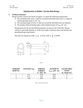
Design a hollow torsion rod, shown in Figure1, to satisfy the following requirements:
1) The calculated shear stress 𝜏 shall not exceed the allowable shear stress 𝜏 𝑎 under the
normal operating torque 𝑇𝑜 (𝑁 ∙ 𝑚).
2) The calculated angle of twist, 𝜃, shall not exceed the allowable twist, 𝜃 𝑎 (radians).
3) The member shall not buckle under a short duration torque of 𝑇 𝑚𝑎𝑥 (𝑁 ∙ 𝑚).
Requirements for the rod and material properties are given in the Table1&2. Design
outside 𝑑 𝑜 and inside diameter 𝑑𝑖 of the rod to make a minimum-mass rod and meet the
preceding design requirements.
The limits for design are: 0.02 ≤ 𝑑 𝑜 ≤ 0.5𝑚 , 0.60 ≤
𝑑𝑖
𝑑 𝑜
≤ 0.999
Figure 1
TORSION
ROD NO.
LENGTH 𝒍 (𝒎) NORMAL
TORQUE
𝑻 𝒐 (𝑲𝑵 ∙ 𝒎)
MAXIMUM
𝑻 𝒎𝒂𝒙 (𝑲𝑵 ∙ 𝒎)
ALLOWABLE
TWIST
𝜽 𝒂 (𝒅𝒆𝒈𝒓𝒆𝒆𝒔)
1 0.5 10.0 20.0 2
2 0.75 15.0 25.0 2
3 1.00 20.0 30.0 2
Table 1 Rod Requirements
2. L u Q i A A E 5 5 0
Final Project Due Dec 12,014
PAGE 2
Material Density,
𝝆 (𝒌𝒈 𝒎 𝟑
)⁄
Allowable
shear stress,
𝝉 𝒂(𝑴𝑷𝒂)
Elastic
modulus,
𝑬 (𝑮𝑷𝒂)
Shear
modulus,
𝑮 (𝑮𝑷𝒂)
Poisson ratio
(𝝊)
4140 alloy
steel
7850 275 210 80 0.30
Aluminum
alloy 24 ST4
2750 165 75 28 0.32
Magnesium
alloy A261
1800 90 45 16 0.35
Berylium 1850 110 300 147 0.02
Titanium 4500 165 110 42 0.30
Table 2 Rod Materials and Properties
II. Design variables, Objective function and Constraints.
The design variables in this project are rod inside diameter divided by outside diameter, rod
outside diameter, rod type and rod material.
Use 𝑥1 to represent the ratio of inside diameter divided by outside diameter
𝑑𝑖
𝑑 𝑜
and
𝑥2 ( 𝑢𝑛𝑖𝑡 𝑖𝑛 𝑚𝑒𝑡𝑒𝑟) to represent outside diameter 𝑑 𝑜. Thus the inside diameter
is 𝑥1 𝑥2 (𝑢𝑛𝑖 𝑖𝑛 𝑚𝑒𝑡𝑒𝑟) . Using this way is because there are explicit bounds on 𝑥1 and 𝑥2.
Rod type was represented by 𝑥3, and Rod material was represented by 𝑥4.
Objective function:
𝑀 =
𝜋
4
𝜌𝑙[𝑥2
2
− (𝑥1 𝑥2)2
], 𝑘𝑔
Constraints:
Calculated shear stress:
𝜏 =
𝑐
𝐽
𝑇𝑜 ≤ 𝜏 𝑜 , 𝑃𝑎
𝑊ℎ𝑒𝑟𝑒 𝑐 𝑖𝑠 𝑑𝑖𝑠𝑡𝑎𝑛𝑐𝑒 𝑓𝑟𝑜𝑚 𝑟𝑜𝑑 𝑎𝑥𝑖𝑠 𝑡𝑜 𝑒𝑥𝑡𝑟𝑒𝑚𝑒 𝑓𝑖𝑏𝑒𝑟(𝑚), 𝐽 𝑖𝑠 𝑝𝑜𝑙𝑎𝑟 𝑚𝑜𝑚𝑒𝑛𝑡 𝑜𝑓 𝑖𝑛𝑒𝑟𝑡𝑖𝑎 (𝑚4
)
𝑐 =
𝑥2
2
, 𝐽 =
𝜋(𝑥2
4
− 𝑥1
4
𝑥2
4
)
64
Thus, 𝒈 𝟏(𝒙) = 32𝑥2 𝑇𝑜 − 𝜋𝜏 𝑜 𝑥2
4
+ 𝜋𝜏 𝑜 𝑥1
4
𝑥2
4
Calculated angle of twist:
𝜃 =
𝑙
𝐺𝐽
𝑇𝑜 ≤ 𝜃 𝑎 , 𝑟𝑎𝑑𝑖𝑎𝑛𝑠
Thus, 𝒈 𝟐(𝒙) = 64𝑙𝑇𝑜 − 𝜋𝜃 𝑎 𝐺𝑥2
4
(1 − 𝑥1
4
)
Critical buckle torque:
𝑇𝑐𝑟 =
𝜋𝑥2
3
𝐸
12√2(1 − 𝜐2)0.75
(1 − 𝑥1)2.5
≤ 𝑇 𝑚𝑎𝑥
Thus, 𝒈 𝟑(𝒙) =
𝜋𝑥2
3 𝐸
12√2(1−𝜐2)0.75
(1 − 𝑥1)2.5
− 𝑇 𝑚𝑎𝑥
3. L u Q i A A E 5 5 0
Final Project Due Dec 12,014
PAGE 3
Bounds Constraints:
0.60 ≤ 𝑥1 ≤ 0.999
0.02 ≤ 𝑥2 ≤ 0.5𝑚
1 ≤ 𝑥3 ≤ 3
1 ≤ 𝑥4 ≤ 5
III. Methods selection, options and reason.
In this project, Genetic Algorithm (GA) was chosen. Because from problem statement, there
are three kinds of rod type, five type of materials and inside diameter, outside diameter
needed to be selected and designed. Rod types and material selection are discrete integer
variables, two diameters are continuous variables. Therefore, it is a combinational
problem.GA method is able to handle this kind of problem.
𝑥1 𝑥2 𝑥3 𝑥4
Bits 12 13 2 3
Resolution 9.7436e-05 5.86e-5 (m) 1 1
The number of bits for 𝑥3 is 2, so the last one is set to represent No.1 style again.
Code Torsion Rod No.
00 1
01 2
10 3
11 1
Table 3 Code for Torsion Rod Type
Same reason for 𝑥4, below is the coding table.
Code Rod Material
000 4140 alloy steel
001 Aluminum alloy 24 ST4
010 Magnesium alloy A261
011 Beryllium
100 Titanium
101 4140 alloy steel
110 Aluminum alloy 24 ST4
111 Magnesium alloy A261
Table 4 Code for Rod Material
Here, total number of bits 𝑙 = 12 + 13 + 2 + 3 = 30. According the guidelines in AAE550,
𝑁𝑝𝑜𝑝 = 4𝑙 = 120, 𝑃𝑚 =
𝑙+1
2(𝑁 𝑝𝑜𝑝×𝑙)
= 0.0043 . Population size is 120 and mutation rate is
0.0043.
4. L u Q i A A E 5 5 0
Final Project Due Dec 12,014
PAGE 4
For this project, the step-linear forms of penalty function was used. The initial penalty
multiplier was set as 10.
𝑃𝑗(𝑥) = {
0 𝑖𝑓 𝑔𝑗(𝑥) ≤ 0
𝑐𝑗[1 + 𝑔𝑗(𝑥)] 𝑒𝑙𝑠𝑒
To get a better penalty multiplier, test different values to check the constraints:
Multiplier 𝒓 𝒑 𝒈 𝟏 𝒈 𝟐 𝒈 𝟑
10 −0.064 × 10⁵
−3.56 × 10⁵
−0.193 × 10⁵
0.1 −0.31 × 10⁵
−6.18 × 10⁵
−0.195 × 10⁵
1 × 10⁻³
−0.071 × 10⁵
−4.24 × 10⁵
−0.195 × 10⁵
1 × 10⁻⁵
4.46 × 10⁴
−0.104 × 10⁴
−0.189 × 10⁵
Table 5 Penalty Multiplier Comparison
The last row in table5 shows g1 violates the constraint. When 𝑟𝑝 are 10 and 1 × 10⁻³
,
constraint value are smaller than the second row. Thus, the multiplier was selected as 10.
IV. Result
Number of
generations
Function
evaluations
𝒙∗
𝒎(𝒌𝒈) 𝒈(𝒙∗
) 𝑷𝒉𝒊(𝒙∗
)
Material
&Type
Run1
48 5880 {
0.9971
0.3828 (𝑚)
4
7
0.9011 {
−0.039 × 10⁵
−4.28 × 10⁵
−0.196 × 10⁵
0.9011
Torsion Rod
No. 1
Aluminum
alloy
Run2
53 6480 {
0.9981
0.4626 (𝑚)
4
2
0.8668 {
−0.297 × 10⁵
−7.32 × 10⁵
−0.198 × 10⁵
0.8668
Torsion Rod
No. 1
Aluminum
alloy
Run3
46 5640 {
0.9968
0.4276 (𝑚)
4
4
0.8597 {
−0.012 × 10⁶
−6.63 × 10⁶
−0.0174 × 10⁶
0.8597
Torsion Rod
No. 1
Beryllium
Run4
56 6840 {
0.9975
0.4845 (𝑚)
1
4
0.8384 {
−0.032 × 10⁶
−8.39 × 10⁶
−0.018 × 10⁶
0.8384
Torsion Rod
No. 1
Beryllium
Table 6 Combination Result
From table6, all three constraints are not violated, which means all 𝑥∗
are feasible. Rod
with material Beryllium (Run 3 and Run4) has lower mass than Aluminum ones (Run 1
and Run2). And Run 4 has the lowest mass. For Run4, the inside diameter is 0.4845 ×
0.9975 = 0.4833 𝑚
It should be noticed that for 𝑥3, 1 and 4 both mean rod type no.1. For 𝑥4, 2 and 7 both
mean Aluminum alloy 24 ST4.
5. L u Q i A A E 5 5 0
Final Project Due Dec 12,014
PAGE 5
Thus, the optimum result is: inside diameter 𝑑𝑖 = 0.4833 𝑚, outside diameter 𝑑 𝑜 =
0.4845 𝑚, rod type is No1(length=0.5 m), material is Beryllium.
V. Discussion & Comments
As previous paragraph discussed, all constraints are negative, which means this rod can take
designed load or torque. Also, 0.4833 𝑚 and 0.4845 𝑚 are less than desired bound 0.5 𝑚, so
it makes sense to me.
The first design variable 𝑥1 is
𝑑𝑖
𝑑 𝑜
, because
𝑑𝑖
𝑑 𝑜
has the explicit bounds. If I replaced it as
just 𝑑𝑖, the objective function would be in quadratic form. Newton’s Method can handle this
objective function better, SQP method also can separate linear and non-linear constraints
better. However, because of the combinational problem, GA is used to solve this problem
and the result is global minimum.
In table6 the second column, number of function evaluations is around 6000, it would change
every time because of the GA method mechanism.
In the set-up problem coding part, I used “if … else…” to get rod type and rod material,
which are both parameters for calculating mass and constraint value. Thus, this part is similar
to AAE550 homework3 part IV, it does not give me too much trouble in coding.
For the supplement step, maybe I can search the price for different material, and compute the
total price cost. In this case, this problem became a multi-objective problem (Mass vs. Cost).
Thus, the result would show different cost for the optimum results.
6. L u Q i A A E 5 5 0
Final Project Due Dec 12,014
PAGE 6
VI. Appendix
GApro.m
function phi = GApro(x)
%AAE550 final project
%created by Lu Qi 12/4/2014
% x has four components: x1 di/do; x2 do; x3 rod type; x4 rod material;
if x(3)==1 %Rod type1
l=0.5; %length (m);
To=10.0*1000; %Normal torque(N*M);
Tmax=20.0*1000; %Maximum Tmax (KN*M);
Thetaa=2*0.0174532925; %Allowable twist (Radians);
elseif x(3)==2 %Rod type2
l=0.75;
To=15.0*1000;
Tmax=25.0*1000;
Thetaa=2*0.0174532925;
elseif x(3)==3 %Rod type3
l=1.0;
To=20.0*1000;
Tmax=30.0*1000;
Thetaa=2*0.0174532925;
else %Rod type1
l=0.5; %same as 1st situation;
To=10.0*1000;
Tmax=20.0*1000;
Thetaa=2*0.0174532925;
end
if x(4)==1 || x(4)==6 %Alloy stell
rho=7850; %Density (kg/m^3);
Taua=275*1000000; %Allowable shear stress (pa);
E=210*10^9; %Elastic modulus (pa);
G=80*10^9; %shear modulus (pa);
v=0.30; % Poisson ratio;
elseif x(4)==2 || x(4)==7 %Aluminum
rho=2750;
Taua=165*1000000;
E=75*10^9;
G=28*10^9;
v=0.32;
elseif x(4)==3 %Magnesium
rho=1800;
Taua=90*1000000;
E=45*10^9;
G=16*10^9;
v=0.35;
elseif x(4)==4 %Berylium
rho=1850;
Taua=110*1000000;
E=300*10^9;
G=147*10^9;
v=0.02;
7. L u Q i A A E 5 5 0
Final Project Due Dec 12,014
PAGE 7
callGApro.m
elseif x(4)==5 %Titanium
rho=4500;
Taua=165*1000000;
E=110*10^9;
G=42*10^9;
v=0.30;
else %Magnesium
rho=1800;
Taua=90*1000000;
E=45*10^9;
G=16*10^9;
v=0.35;
end
m=pi/4*rho*l*(x(2)^2-x(1)^2*x(2)^2);
g(1)=32*x(2)*To-pi*Taua*x(2)^4+pi*Taua*x(1)^4*x(2)^4;
g(2)=64*l*To-pi*Thetaa*G*x(2)^4*(1-x(1)^4);
g(3)=pi*x(2)^3*E/12/2^0.5/(1-v^2)^0.75*(1-x(1))^2.5-Tmax;
%Penalty function ---step linear
P=0.0;
for i=1:3
if g(i)<=0
P = P+0.0;
else
P = P + 10* (1+g(i));
end
end
phi=m+P;
end
% this file provides input variables to the genetic algorithm
% upper and lower bounds, and number of bits chosen for AAE550 final
% project;
% Modified on 2014/12/4 by Lu Qi;
%x has 4 componenets, upper bounds and lowers are in the content
clc;
close all;
clear all;
options = goptions([]);
vlb = [0.60 0.02 1 1]; %Lower bound of each gene - all variables
vub = [0.999 0.5 4 8]; %Upper bound of each gene - all variables
bits =[12 13 2 3]; %number of bits describing each gene - all variables
format long;
[x,fbest,stats,nfit,fgen,lgen,lfit]=
GA550('GApro',[ ],options,vlb,vub,bits);
![L u Q i A A E 5 5 0
Final Project Due Dec 12,014
PAGE 2
Material Density,
𝝆 (𝒌𝒈 𝒎 𝟑
)⁄
Allowable
shear stress,
𝝉 𝒂(𝑴𝑷𝒂)
Elastic
modulus,
𝑬 (𝑮𝑷𝒂)
Shear
modulus,
𝑮 (𝑮𝑷𝒂)
Poisson ratio
(𝝊)
4140 alloy
steel
7850 275 210 80 0.30
Aluminum
alloy 24 ST4
2750 165 75 28 0.32
Magnesium
alloy A261
1800 90 45 16 0.35
Berylium 1850 110 300 147 0.02
Titanium 4500 165 110 42 0.30
Table 2 Rod Materials and Properties
II. Design variables, Objective function and Constraints.
The design variables in this project are rod inside diameter divided by outside diameter, rod
outside diameter, rod type and rod material.
Use 𝑥1 to represent the ratio of inside diameter divided by outside diameter
𝑑𝑖
𝑑 𝑜
and
𝑥2 ( 𝑢𝑛𝑖𝑡 𝑖𝑛 𝑚𝑒𝑡𝑒𝑟) to represent outside diameter 𝑑 𝑜. Thus the inside diameter
is 𝑥1 𝑥2 (𝑢𝑛𝑖 𝑖𝑛 𝑚𝑒𝑡𝑒𝑟) . Using this way is because there are explicit bounds on 𝑥1 and 𝑥2.
Rod type was represented by 𝑥3, and Rod material was represented by 𝑥4.
Objective function:
𝑀 =
𝜋
4
𝜌𝑙[𝑥2
2
− (𝑥1 𝑥2)2
], 𝑘𝑔
Constraints:
Calculated shear stress:
𝜏 =
𝑐
𝐽
𝑇𝑜 ≤ 𝜏 𝑜 , 𝑃𝑎
𝑊ℎ𝑒𝑟𝑒 𝑐 𝑖𝑠 𝑑𝑖𝑠𝑡𝑎𝑛𝑐𝑒 𝑓𝑟𝑜𝑚 𝑟𝑜𝑑 𝑎𝑥𝑖𝑠 𝑡𝑜 𝑒𝑥𝑡𝑟𝑒𝑚𝑒 𝑓𝑖𝑏𝑒𝑟(𝑚), 𝐽 𝑖𝑠 𝑝𝑜𝑙𝑎𝑟 𝑚𝑜𝑚𝑒𝑛𝑡 𝑜𝑓 𝑖𝑛𝑒𝑟𝑡𝑖𝑎 (𝑚4
)
𝑐 =
𝑥2
2
, 𝐽 =
𝜋(𝑥2
4
− 𝑥1
4
𝑥2
4
)
64
Thus, 𝒈 𝟏(𝒙) = 32𝑥2 𝑇𝑜 − 𝜋𝜏 𝑜 𝑥2
4
+ 𝜋𝜏 𝑜 𝑥1
4
𝑥2
4
Calculated angle of twist:
𝜃 =
𝑙
𝐺𝐽
𝑇𝑜 ≤ 𝜃 𝑎 , 𝑟𝑎𝑑𝑖𝑎𝑛𝑠
Thus, 𝒈 𝟐(𝒙) = 64𝑙𝑇𝑜 − 𝜋𝜃 𝑎 𝐺𝑥2
4
(1 − 𝑥1
4
)
Critical buckle torque:
𝑇𝑐𝑟 =
𝜋𝑥2
3
𝐸
12√2(1 − 𝜐2)0.75
(1 − 𝑥1)2.5
≤ 𝑇 𝑚𝑎𝑥
Thus, 𝒈 𝟑(𝒙) =
𝜋𝑥2
3 𝐸
12√2(1−𝜐2)0.75
(1 − 𝑥1)2.5
− 𝑇 𝑚𝑎𝑥](data:image/gif;base64,R0lGODlhAQABAIAAAAAAAP///yH5BAEAAAAALAAAAAABAAEAAAIBRAA7)