This document provides instructions for operating a Mini Fiber Optic Cable Blowing Machine. It includes:
1) Selecting the proper cable seals based on cable diameter to prevent air leaks during operation.
2) Guidance on properly positioning the cable and duct for blowing.
3) Details on connecting compressed air and controlling the direction and speed of cable blowing.
4) Steps for adjusting the exit box position based on different cable sizes.
5) Instructions for changing out pallets and monitoring air pressures during use.
Beginners Guide to TikTok for Search - Rachel Pearson - We are Tilt __ Bright...
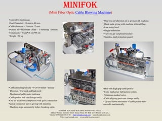
Minifok
1. •Controll by technician.
•Duct Diameter =10 mm to 40 mm.
•Cable diameter = 5 mm to 12 mm.
•Needed air= Minimum 15 bar - 1 metercup / minute.
•Dimensions= 44cm*36 cm*59 cm
•Weight =50 kg
•Cable installing velocity =0-30-50 meter / minute
• Direction =Forward and backward
• Mechanical cable meter indicator
•Cable pusher belt can change easily.
•One air inlet from compressor with quick connection
•Quick connection part is giving with machine.
• Machine stops automaticly before breaking cable.
MINIFOK
(Mini Fiber Optic Cable Blowing Machine)
•One box air lubriction oil is giving with machine.
•Hand tools giving with machine with soft bag.
•Low noisy level.
•Single technician
•Valve to get out presurrized air
•Stainless steel protection guard
•Belt with high grip cable profile
•Festo marked air lubrication system.
•Mindman marked valve.
•Cable aligning parts can change easily.
• Up and down movement of cable pusher belts
controlls mechanically.
KOSMAK MACHINE BUILDING INDUSTRY LTD.CO.
Address=Sanayi mahallesi İzmit Sanayi Sitesi 201 Blok no=6/8 İzmit KOCAELİ
Telefon=0090 262 335 24 00 Mail=info@kosmak.com / kamerkos@kosmak.com
Web=www.kosmak.com www.cable.blowing.com.tr
2. 1)Selection Nutrings
First measure cable diameter with callipers (figure 1).The inside diameter of cable seal’s (figure 2)
must be same with cable’s outside diameter also cable seal need to work slippery on cable (figure 3)
to not to make air leakage.Cut cable seals as you see on figure 4 to not to make air leakage.
NOTE:You need to inform us cable diameter with machine order.
1
2Canals of the selected cable seals must locate to the installing way of cable. If not ,you
can not use compressed air productively (figure5-1).Touch faces of black o-rings with cable
seals must be cutted angular (figure5-2)
Figure 1 Figure 2
Figure 3 Figure 4
Figure 5
2)Establishing Cable
Figure 6 Figure 7 Figure 8 Figure 9
1)First turn the black handling part in the direction of red arrow to move up palette. 2) Change the parts on the figure 7-1 , figure 8-1 and figure 8-2 as your cable diameter.
3)Then see the cable is straight as in the figure 9.If cable is not straight you need to move exit box up or down.
1
2
1
3)Establishing Duct
Figure 10 Figure 11 Figure 12
1)Orings must be established well to not to have air leakage.
2)Duct must be placed as inthe figure 11.
3)Press the duct with aluminium part and tighten the nuts to not to
shoot out duct under air compression.
4)Giving Air to the Machine and Cable
Connect 1 inch air hose (figure 13-a) with quick air connection
part (figure 13-b).
Quick air connection part is given with machine.
Make connection as hydraulic pipe connections , not to get out
under pressure.
Quick connection main body is assembled on machine as you see
on figure 14- c.
Connect part b with part c as in figure 15.
.
Figure 14 Figure 15
Figure 17
a
b
c
d e
Figure 13
Figure 16
Open the vane as in figure 16 –d to give air to the duct.
Open the vane as in figure 17 –e to give air to the motors of machine.
5) Giving Motion To the Cable
You can regulate blowing direction (right or left) and speed (0-60m/min) of cable by moving direction control valve.
NOTE:You must use stop position when you are changing the direction.If you pass the opposite direction directly and don’t stop on stop position this will
damage the gears of air motors.
Figure 18
3. 33
6)SETTING AXIS LINE OF EXIT BOX FOR DIFFERENT CABLES
Figure 18 Figure 19 Figure 20
Figure 21
1
2
4
1)Take out air pipe (part 1) on the figure 18.
2)Remove bolt (part 2) on the figure 19.
3)Turn metal pipe group (part 3)to the direction of the
arrow on the figure 20.
4)Loosen the bolts (two bolts on figure 21 part 4 and
one bolt on figure 22) and move exit box up or down to
set axis line.
3
5
Figure 22
7)CHANGING PALLETTES
1
2
1)You need to take out chrom
guard to change
pallettes.Loosen four bolts
(figure 22 part1) then take
guard out side.
2)Turn two metal black parts
on figure (figure 22 part 2) on
the direction of arrows then you
can take out pallettes by turning
pallettes with hand.
2
1
8) AIR PRESSURES
You can see the air pressure on motors
on the gauge (figure 23 part 1).It must be
between 6 and 7 while machine is
working.Turn blue handle (part 3) to
increase and decrease air pressure.
You can see the air pressure in duct on
the gauge (figure 23 part 2).The pressure
in the duct must be between 10 and 12
bar while cable blowing.
Figure 22
Figure 23
1
3
To maintain air motors, open oil set screw until end (Figure 24-1)
and run motors 30-35 secs on this position. This operation supplies
bearing lubrication for air motors and parts.
This operation must be repeated in every evening after the work
ends, if not the moisture collected in motors will cause the bearings
to rust.
The foreign objects entering into reservoir (figure 24-2) causes to
the filter (figure 25-1) be blocked.This changes its colour and its
shape.You must change this filter before this case occurs ,if not air
pressure yield will be less and you will have problems about the
machine.
You can see the demontaging of air filter on figure 25.Firstly open
reservoir (figure 25-3) then open nut (figure 25-2) then you can
take air filter (figure 25-1)
Figure 24
Figure 25
9)AIR FILTER GROUP
1
2
1
2
3