SlideShare a Scribd company logo
1 of 192
Download to read offline
S e r i e s
W o r l d S u p e r
MOLDED-CASE CIRCUIT BREAKERS
EARTH-LEAKAGE CIRCUIT BREAKERS
09
A
INDEX This material has been prepared for those who use the products for
manufacturing assemblies, for holding electric works, for holding
maintenance and for the others acquainted with electric expertise
including those who operate the products (final users).
Introduction 1........................................................................................................................................
Features 3..............................................................................................................................................
The Great Variable Accessories for Perfect Solution (Product Skeleton) 9.....................................
1. Series Configuration and List of Product Models 11......................................................................
Molded-Case Circuit Breakers
Earth-Leakage Circuit Breakers
Earth-Leakage Circuit Breakers for CE Marking
Motor-Protection Breakers
UL Listed Products
Miniature Circuit Breakers
ELRs and ZCTs
Circuit Protectors
........................................................................................................................................
......................................................................................................................................
...........................................................................................................
..............................................................................................................................................
..........................................................................................................................................................
...............................................................................................................................................
.................................................................................................................................................................
.............................................................................................................................................................
13
21
25
29
30
31
35
37
2. Detailed Specifications 13.................................................................................................................
3. Special-purpose Breakers 38............................................................................................................
Mag Only (Instantaneous tripping circuit breakers)
DC MCCBs and DSN Switches
400Hz MCCBs
Low-Instantaneous MCCBs
Generator-Protection MCCBs
Measuring Display Unit (MDU) Breakers
............................................................................................................
........................................................................................................................................
...................................................................................................................................................................
.............................................................................................................................................
.........................................................................................................................................
........................................................................................................................
38
38
39
39
39
40
1. Connection Types
2. Connection Accessories
3. Connection of Line and Load
......................................................................................................................................................................
............................................................................................................................................................
.....................................................................................................................................................
46
46
46
4. Connection Method 46......................................................................................................................
6
5
4
3
2
1
7
8
9
Internal Accessories
1. Accessories
2. Switch Operation and Rating
3. Maximum Number of Internally Mounted Accessories
4. Shunt Trip (SHT)
5. Undervoltage Trip (UVT)
6. Test Button Module (TBM)
7. Lead-wire Specifications
8. Internal Terminal (INT)
9. Vertical Lead-wire Terminal Block (SLT)
10. Pre-Alarm Module (PAL)
11. 3ø4W Neutral-pole protection Relay (NR)
External Accessories
1. F-type Operating Handle (Breaker Mount Type)
2. V-type Operating Handle (Door Mount Type)
3. S-type Operating Handle
4. Terminal Cover
5. Electrical Operation Device
6. Mechanical Interlocks (MI)
7. Handle Lock Devices and Card Holder
8. IEC 35mm Rail Mounting Adapters
.........................................................................................................................................................
...............................................................................................................................................................................
.....................................................................................................................................................
..............................................................................................................
........................................................................................................................................................................
.............................................................................................................................................................
.........................................................................................................................................................
............................................................................................................................................................
................................................................................................................................................................
....................................................................................................................................
..........................................................................................................................................................
...............................................................................................................................
.......................................................................................................................................................
.........................................................................................................................
..............................................................................................................................
............................................................................................................................................................
...........................................................................................................................................................................
........................................................................................................................................................
.........................................................................................................................................................
......................................................................................................................................
............................................................................................................................................
47
47
47
48
55
55
56
56
56
57
58
59
60
60
63
68
70
71
79
80
80
Molded-Case Circuit Breakers and Motor Breakers
Earth-Leakage Circuit Breakers
Earth-Leakage Circuit Breakers for CE Marking
UL 489 Listed Molded-Case Circuit Breakers
Miniature Circuit Breakers
DIN Series
Circuit Protectors
.....................................................................................................
...................................................................................................................................
.........................................................................................................
..............................................................................................................
............................................................................................................................................
.......................................................................................................................................................................
...........................................................................................................................................................
81
117
141
161
173
177
181
Molded-Case Circuit Breakers
Earth-Leakage Circuit Breakers
......................................................................................................................................
...................................................................................................................................
183
183
Caution
The manual covers the product specifications for selecting an appropriate
low-voltage breaker. There is the “HANDLING AND MAINTENANCE”
describing how to handle the products. To use the products, separately
request the “HANDLING AND MAINTENANCE”, for correct operation.
5. Accessories 47...................................................................................................................................
6. Characteristics and Dimensions 81..................................................................................................
7. Ordering Information
(http://www.MitsubishiElectric.co.jp/haisei/lvs/)
183...................................................................................................................
8. Melshort 2 184....................................................................................................................................
9. Low-voltage switchgear Technical information service via the internet
(A Smarter, Easier Way to Select Breakers)
185..............................
1
1
Full range of MITS
(30A to 16
GloGlo
Compliance with w
S e r i e s
W o r l d S u p e r
ASTA
TPC
TUV
CCC
LR GL BV NKDNV ABS
SABS
JIS
GB
EN
IEC
CCS
New Digital ETR
High-PerformanceHigh-Performance
Downsizing of 630AF, New Digital ETR
Volume 60% downsized
210
275
140
257
Previous New
0.01
0.1
1
10
1 x 10²
1 x 10³
1 x 10⁴
Current (A)
Time(s)
Ir
Current setting
Is
Short-delay
tripping current
TL
High-voltage fuse-
Allowable short-time
characteristics
Long-delay operating time
Short-delay
operating timeTs
Ii Instantaneous tripping current
Current-converted value
on the high-voltage side
Ip
Pre-alarm
current
Load current
High
voltage
Low
voltage
Transformer
NFB
(electronic)
M
Load
Switch
with fuse
250AF (Type“SGW, HGW, RGW, UGW”) Product Skelton
Best SolutionBest Solution
Plenty of accessories, Easy installation
24
23
22
16
17
18
19
20
21
7
745
11 12 13
8
6
9
15
398
1312
2
10
1110
1
14
2
UBISHI WS Series
00A frame)
obalbal
orldwide standards
CSA
UL
Mechanism
Terminal
Internal Accessories External Accessories
Breaking PerformanceRelay
Shunt-less Advanced ISTAC PA Auto-Puffer
JPT
ReliableReliable
High reliability, Best performance
IntelligentIntelligent
Measuring and communicating
Personal
Computer
MELSECNET/10
Interface card MELSECNET/10
Interface
Unit
MDU
Eco Monitor Pro ME96NSR
AE-SW
PLC
I/O Unit
CC-Link®
By using various application software for PLC, users can also connect to the
network SCADA system.
Global Compliance with worldwide standards
3
ASTA
TPC
TUV
CCC
LR GL BV NKDNV ABS
SABS
CSA
UL
JIS
GB
EN
IEC
CCS
WS Series International Standard Conformance List
Standards
IEC JIS EN
International Japan Europe
GB
China
UL CSA LR GL DNV ABS BV NK
USA Canada
Safety Certification Marine Approvals
UK Germany Norway USA France Japan
CCS
China
• Compliance with worldwide standards (IEC/JIS/EN/GB/UL/CSA)
• Applicable to marine approvals
• New design with Laser Marking
• All products with lsolation function
• RoHS compliance
S e r i e s
W o r l d S u p e r
■ Full range of WS Series (up to 1600AF)
NF-C
NF-S
NF-H
NF-U
NV-C
NV-S
NV-H
NV-U
MCCB
ELCB
AF 125 250 400 630 800 1250 160010001606332(30)
NF30-CS
NF32-SW
NV30-CS
NV32-SW
NF63-CW
NF63-SW
NF63-HW
NV63-CW
NV63-SW
NV63-HW
NF125-CW
NF125-SW
NF125-SGW
NF125-HW
NF125-HGW
NF125-RGW
NF125-UGW
NV125-CW
NV125-SW
NV125-HW
NV125-RW
NF160-SW
NF160-SGW
NF160-HW
NF160-HGW
NF250-CW
NF250-SW
NF250-SGW
NF250-HW
NF250-HGW
NF250-RGW
NF250-UGW
NV250-CW
NV250-SW
NV250-SEW
NV250-HW
NV250-HEW
NV250-RW
NF400-CW
NF400-SW
NF400-SEW
NF400-HEW
NF400-REW
NF400-UEW
NV400-CW
NV400-SW
NV400-SEW
NV400-HEW
NV400-REW
NF630-CW
NF630-SW
NF630-SEW
NF630-HEW
NF630-REW
NV630-CW
NV630-SW
NV630-SEW
NV630-HEW
NF800-CEW
NF800-SEW
NF800-SDW
NF800-HEW
NF800-REW
NF800-UEW
NV800-SEW
NV800-HEW
NF1000-SEW NF1250-SEW
NF1250-SDW
NF1600-SEW
NF1600-SDW
NF250-SGW 3P
✽ RoHS…The Restriction of the use of certain Hazardous Substances in Electrical and Electronic Equipment
High-Performance
Downsizing,
New Digital ETR S e r i e s
W o r l d S u p e r
4
0.01
0.1
1
10
1 x 10²
1 x 10³
1 x 10⁴
Ir
Current setting
Is
Short-delay
tripping current
Current (A)
Time(s)
0.01
0.1
1
10
1 x 10²
1 x 10³
1 x 10⁴
Current (A)
Time(s)
Ir
Current setting
Is
Short-delay
tripping current
TL
High-voltage fuse-
Allowable short-time
characteristics
Long-delay operating time
Short-delay
operating timeTs
Ii Instantaneous tripping current
Current-converted value
on the high-voltage side
Ip
Pre-alarm
current
Load current
High
voltage
Low
voltage
Transformer
NFB
(electronic)
M
Load
Switch
with fuse
● 630AF models downsized to the size of 400AF model, contributing to
compact panels and simplification of design.
● MCCB-AC/DC common use (excl. Electronic trip type)
3-pole:available up to 400VDC, 4-pole:available up to 500VDC
(NF400-SW, NF630-SW)
● Improved breaking capacity at 690VAC (NF400-HEW, NF630-HEW)
■ 400AF, 630AF & 800AF models easier to use
● Installed digital ETR same as Electronic relay for under 800AF
• Multi adjustment available (Long time delay, short time delay,
Instantaneous, pre-alarm characteristics):easier coordination with upper
breakers.
• Pre-alarm equipped as Standard:LED turned on when load current
exceeds pre-alarm setting current.
• Suitable for use as a main breaker:isolation comformity to IEC Standard.
■ NEW Digital ETR (Electronic Trip Relay) for
NF1000-SEW, NF1250-SEW & NF1600-SEW
Volume 60% downsized
210
275
Previous
Icu/Ics
15/15 kA
New
35/18 kA
Icu/Ics
140
257
Previous New
Previous
Icu/Ics
45/45 kA
New
50/50 kA
Icu/Ics
● Improved breaking capacity at 400/415VAC (NF400-SEW, NF630-SW/SEW, NF800-SEW)
Previous New
Rated current
Short time-delay
tripping current
Instantaneous
tripping currentCurrent setting
Short time-delay
operating time
Pre-alarm
current
Long time-delay
operating time
• Isolation suitability
• Class ll insulation
• Increased operating cycles
• Increased lcu
• High voltage
• Ics=100% lcu
Relay Mechanism
Internal Accessories External Accessories
Breaking Performance
■ Technology for WS Series
• Cassette-type accessories
• Wide range of Rated Voltage
Shunt-less
JPT
Advanced ISTAC PA Auto-Puffer
Polymer Ablation type Auto-Puffer [Adopted on SGW,
HGW, RGW, UGW]
Advanced Impulsive Slot-Type Accelerator [Adopted on SGW,HGW,
RGW, UGW ]
Jet Pressure Trip Mechanism [Adopted on SGW,
HGW, RGW, UGW]
• IP20 Mold-cover Finger
protection
• Front compression terminal
⇔ Box terminal ⇔ Rear ⇔
PM
• Electric operators
➀ High speed type
➁ Isolation suitability
• IP20 PM with Safety Device
• Handle Lock Device
• F/V handle
• IP40 Terminal cover
• Relay-unit Thermal type & Electronic type
• AC/DC common use
• Thermal adjustable range is expanded.
Terminal
Shunt-less Current Flow Technology [Adopted on SGW,
HGW, RGW, UGW]
Double plates conductors hold the movable conductor without
flexible wires. This shunt-less structure achieves the increased
operating cycles.
[PA Auto-Puffer] [JPT]
[Advanced ISTAC]
[Shunt-less]
Endurance
(C-O cycles)
(times)
50,000
40,000
30,000
20,000
10,000
0
Electrical Mechanical
NF125-SGW/HGW NF160-SGW/HGW NF250-SGW/HGW
Holder
Movable contact
Movable contact
revolving shaft
Spring
During revolution the movable contact is constantly
in contact with the holder, maintaining current flow.
Reliable High reliability, Best performance
5
■ Best performance of SGW / HGW / RGW / UGW
■ 2 types of Relay for SGW / HGW / RGW / UGW
85
100
125
200 200 200 200 200 200
125 125 125 125 125
36
75 75
70
65
50
20
25
30
36 36 36
30
8
Series
Breaking Capacity lcu/lcs
200
150
100
50
0
(kA)
230VAC
380VAC
400VAC 415VAC
440VAC
500VAC
690VAC
U(UGW)
R(RGW)
S(SGW)
H(HGW)
Max.let-through peak current (kA) (400VAC)
Max.peakcurrent(kA)
Short-Circuit Current, sym.r.m.s.(kA)
Prospective short-circuit
current asym. peak
NF250-HGW
NF250-UGW
200
100
80
60
40
20
10
8
6
4
2
1
1 2 4 6 8 10 20 40 60 80 100 200
I2
t let-through characteristics (400VAC)
MAX.I2
t(A2
•s)
Short-Circuit Current, sym.r.m.s.(kA)
10
8
6
4
2
1
0.8
0.6
0.4
0.2
0.1
0.08
0.06
0.04
1 2 4 6 8 10 20 40 60 80 100 200
NF250-HGW
NF250-UGW
(✕106
)
T
lr li l
li(DC)=1.3Xli(AC)
li(X250AAC)
4 10
160
200
2506 8
lr lr(A)li
MODEL
RT 250
ln 250 A
50/60Hz MADE IN JAPAN
LN326N433-13P3E
Thermal Adjustable Relay
NF250-SGW/HGW
NF160-SGW/HGW
NF125-SGW/HGW
Hi
Lo
Rating ln(A) 25 40 63 100 125 160 250
Type
Overload Protection (Thermal)
Short-Circuit Protection (Magnetic)
Tripping threshold lr (A)
Neutral protection (✽1)
4P3E
4P4E
16-25 25-40 40-63 63-100 80-125 125-160 160-250
No Protection
1 ✕ lr
Tripping threshold li
Fixed
10✕ln (AC), 13✕ln (DC)
Adjustable
4 to 10✕ln (AC), 5.2 to 13✕ln(DC)
Note (✽1) The type 4P3E is standard. If the type 4P4E is required, specify the type 4P4E separately and explicitly.
lr
li
l
lp
ls
Ts
TL
T
Electronic Relay
LN326N429-11
MADE IN JAPAN
MODEL
RE250
AC only
Ir
125
160
200
250 12
60 80
100 2
3
4 5 6
7
8
10 0.6
1
2
T
I
Ip
TL Is
Ts
Ii
Ir
3 4 7
7.5
8.5
9.5
4P3E 4P4E8 9
10
6
8 10
12
14
2.5
3.5
(A) L(s) (XIr)T Is (s)Ts
(X250A)Ii
(XIr)Ip pNITEST
ln 250 A
50/60Hz
OVERPAL70%
Hi
Lo
Rating
Type
ln(A) (40C) 32 63 100 125 160 250
NF250-SGW/HGW
NF160-SGW/HGW
NF125-SGW/HGW
Overload Protection
Short-Circuit Protection
Pre-Alarm (for Indication)
Indicator (LED)
Tripping threshold lr (A)
LTD
Tripping time TL(s)
Neutral protection (Slectable)
16-32 32-63 63-100 75-125 80-160 125-250
12-60-80-100 step adjustable (at 2 ✕ lr)
0-1 ✕ lr (Step adjustable)
STD
PAL
INST
Pickup current ls
Tripping time Ts(s)
Tripping threshold li
2-2.5-3-3.5-4-5-6-7-8-10 ✕ lr step adjustable
0.06-0.1-0.2-0.3 step adjustable (at 1.5 ✕ ls)
4 to 14 ✕ ln continuous adjustable
Pickup current lp
Operating time Tp
0.7-0.75-0.8-0.85-0.9-0.95-1.0 ✕ lr step adjustable
TL/2
70%-LED (green)
PAL-LED (orange)
Over-LED (red)
Lights at 0.7 ✕ lr
Flashs at lp and Lights at over Tp
Lights at 1.15 ✕ lr
Thermal type unit
Electronic type unit
S e r i e s
W o r l d S u p e r
6
7
Best Solution Abundant Accessories and Easy Installation
High-speed Motor Device
Motor devices for 125-250AF are now easier to use,contributing to
simple installation.
✽ A spring charge mechanism has been adopted for high-speed
operation. (0.05~0.1sec)
✽ Installation is fast and simple, only requiring two screws.
External Handle
A safer and easy-to-operate handle has been adopted.
✽ Complies with IP65 protection rating standards.
✽ Isolation function achieved through combination with the breaker unit.
✽ Structured to allow relay adjustments after installation as well.
✽ Equipped with a cylinder key (optional) to prevent misuse.
IP-20PM with Safety Device
[Adopted for SGW, HGW]
Specialized for 3- and 4-pole use (incompatible with 2-pole use).
✽ Complies with IP-20 protection rating standards.
✽ A safety device is optional.
✽ Connectable with up to nine leads (for PLT).
✽ Can be modified from front to rear connection.
(Note: Modification by users is not authorized)
IP20: Finger protection.
The adoption of cassette-type internal accessories simplifies use, and
the common use of different voltages realizes a major reduction in the
number of types. Additionally, UVTs are now available for ELCBs and
time delay types have been expanded, offering a wider range of
applications.
✽ Cassette-type Accessories
Giving greater flexibility when upgrading circuits, cassette-type
accessories make ordering easy and enable simple, one-touch
installation. Insulation also improves safety.
Compatible with all breaker series
The alarm switch (AL), auxiliary switch (AX), shunt trip (SHT),
and undervoltage trip (UVT) all come as cassette-type
accessories compatible with all breaker series.
(IP-20PM)
3-way Lead Wire (adjustable)
Vertical lead wire terminal block (SHT)
Lead wire to line side Flying lead wire
1.Push the trip button
(PTT)
2.Loosen the front
cover screws
3.Open the front
cover
4.Install the
accessories
5.Close the front cover
and tighten the screws.
Power Supply Module
V-Handle
Previous models WS Series (New)
UVT
voltage
SHT
voltage
VAC
VDC
VAC
VDC
(24), (48), 100-120, 200-240,
380-450, (440-550)
(12), (24), (36), (48), 100, (110), (125), (220)
100-110, (100-120), 200-220, (220-240),
(380-415), 400-440, (440-480), (500-550)
(24), (48), 100, (110)
24-48, 100-240, 380-550
12, 24-36, 36-48, 100-125, 220-250
24/48, 100-110/120-130, 200-220/230-250,
380-415/440-480, 500-550/690
24/48, 100/110, 110/125
Internal Accessories
External Accessories
8
Intelligent Measuring and Communicating
S e r i e s
W o r l d S u p e r
Product Design Simplifies Use & Expands Applications
IP20 Terminal Connection
Safety of connections has
been increased for SGW
and HGW.
✽ Protection rating of IP20
as standard is ensured.
Connection Flexibility
Compatible with various
connection methods.
Solderless terminals are
now built into the breaker
design the conventional
style where terminals are
affixed on the outside.
Maximum connecting
cable size of 185mm2
(SGW/HGW).
(Note: Certain models have externally attached
terminals.)
Handle Locks
With the WS Series, ON/OFF locking is
possible with the use of a padlock.
Up to three padlocks may be attached.
✽ Customers are requested to use their
own padlocks.
Terminal Cover
Major improvements have been achieved
in front connection terminal safety.
✽ With terminal covers, a protection
rating of IP40 is ensured.
(“SGW, HGW, RGW, UGW”)
IEC Rail Mounting for 32, 63AF
Installation hooks are included
for 32,63AF, markedly
simplifying installation work.
OFF lock with 3 padlocks
(“SGW, HGW, RGW, UGW”)
ON lock OFF lock
Personal
computer
MELSECNET/10
interface card MELSECNET/10
Interface
unit
MDU
Eco Monitor Pro ME96NSR
AE-SW
PLC
I/O unit
CC-Link®
By using various application software for PLCs, users can also connect to the SCADA
system.
• MDU (Measuring Display Unit) with NF 250-800AF
• Compact, white measuring unit
• Measuring data can be transmitted to a PC or a PLC through CC-Link
• AL / AX with CC-Link transmission
• Improved accuracy(electric current): ±2.5% of rated value → ±2.5% of true value
Product Skeleton
9
24
23
22
16
17
18
19
20
21
45
10
10
S e r i e s
W o r l d S u p e r
10
7
7
11 12 13
8
6
9
15
398
1312
2
11
1
14
MCCB
Relay unit (Thermal type) (RT) (✽1)
Relay unit (Electronic type) (RE) (✽1)
Relay unit (Magnetic only type) (RM) (✽1)
Relay unit (Switch-disconnector type) (✽1)
Super current-limiting unit*
Solderless (BOX) terminals
Front connection nuts
Rear connections
Insulating barrier (BA-F)
Small terminal cover (TC-S)
Large terminal cover (TC-L)
Rear terminal cover (BTC)
Plug-in base (PM)
Connections for Plug-in
Mechanical interlock device (MI)
OFF Lock with 3 Padlock (HLF3)
Handle lock device (LC/HLF/HLN/HLS)
(F-type operating handle)
(V-type operating handle)
Electrical operation device (MD)
Alarm/Auxiliary switch device (AL/AX)
Under voltage trip device (UVT)
Shunt trip device (SHT)
1
2
3
4
5
6
7
8
9
10
11
12
13
14
15
16
17
18
19
20
21
22
23
24
Note (✽1) All the accessories are field mounting type
except No.2, 3, 4, 5 and 6.
Series Configuration
Molded-case circuit breakers
Earth-leakage circuit breakers
NF-C
Economy type
NF-S
Standard type
NF-H
High-performance
type
NF-U
Current limiting-type
ultra breaker
NV-C
Economy type
NV-S
Standard type
NV-H
High-performance
type
NV-U
Ultra current-limiting
type
MB
Motor breaker
Motor-protection breakers
NEMA-type for consumer unit DIN-series for general consumer unit
Miniature circuit breakers
BH BH-P BH-S BH-PS BH-D6 BH-DN BV-D BV-DN KB-D
For equipment
Circuit protectors
CP30-BA CP-B CP-S
11
1. Series Configuration and List of Product Models
1
50 100 150 225 250 400 600
UL489 Listed
Molded-case circuit breaker
NF50-SWU
NF100-CWU
NF-SFW NF225-CWU NF-SKW NF-SLW
NF100-SWU
Earth-leakage protector
UL489 Listed
Molded-case circuit breaker
NV50-SWU NV100-SWU
Series
Frame A
UL listed products
NF-UL
UL489 Listed
Molded-case circuit breaker
NV-UL
Earth-leakage protector
UL489 Listed
Molded-case circuit breaker
Miniature Circuit Breakers
ULlisted
products
AF
BH
60 100
BH
BH-P
BH-S —
BH-PS —
DIN Series
AF
MCB
RCCB
Isolating
switch
BH-DN
BH-D6
BV-D
RCBO BV-DN
KB-D
63 and less
Circuit Protectors
AF
CP
CP30-BA
CP-B
CP-S
30 and less
Details will be available
upon request.( )
Details will be available
upon request.( )
32 (30) 63 125 (100) 250 400 630 800 1000 1600
NF-C
Economy type
NF30-CS NF63-CW NF125-CW NF250-CW NF400-CW NF630-CW
NF-S
Standard type
NF-H
High-performance type
NF32-SW
NF63-SW
NF125-SW NF250-SW NF400-SW NF630-SW NF800-SDW
NF1000-SEW
NF1250-SEW
NF1250-SDW
NF1600-SEW
NF1600-SDWNF125-SGW NF250-SGW NF400-SEW NF630-SEW NF800-SEW
NF63-HW
NF125-HW NF250-HW NF400-HEW NF630-HEW NF800-HEW
NF125-HGW NF250-HGW
160
NF160-SW
NF160-SGW
NF160-HW
NF160-HGW NF400-REW NF630-REW NF800-REW
NF-U
Ultra current-limiting type
NF125-RGW NF250-RGW
NF400-UEW NF800-UEW
NF125-UGW NF250-UGW
NV-C
Economy type
NV30-CS NV125-CW
NV125-CW
NV250-CW NV400-CW NV630-CWNV63-CW
NV63-CW
NV-S
Standard type
NV-H
High-performance type
NV32-SW
NV32-SW
NV63-SW
NV63-SW
NV125-SW
NV125-SW
NV250-SW NV400-SW NV630-SW
NV800-SEW
NV250-SEW
NV63-HW
NV63-HW
NV125-HW
NV125-HW
NV250-HW NV400-HEW
NV250-HEW NV400-REW
NV-U
Ultra current-limiting type
NV125-RW
NV125-RW
NV250-RW
MB
Motor breaker MB100-SW MB225-SW
MB30-SW
MB30-CS MB50-CW
MB50-SW
Series
Frame A
List of Product Models
Molded-casecircuitbreakersEarth-leakagecircuitbreakersEarth-leakagecircuitbreakersforCEMarkingMotor-protection
breakers
1250
NV-C
Economy type
NV-S
Standard type
NV-H
High-performance type
NV-U
Ultra current-limiting type
NV-SKWNV225-CWU
NV400-SEW NV630-SEW
NV800-HEWNV630-HEW
NV250-CW NV400-CW NV630-CW
NV250-SW
NV400-SW NV630-SW
NV800-SEW
NV250-HW
NV400-HEW
NV400-REW
NV250-RW
NV400-SEW NV630-SEW
NV800-HEWNV630-HEW
NF-SJW
NF-HJW
NF800-CEW
12
Series
Frame Size
Image
Type name
Rated current in (Amp.)
Rated ambient temperature (°C)
Number of poles
Rated insulation voltage Ui (V)
Rated
short-circuit
breaking
capacities (kA)
IEC 60947-2
(Icu/Ics)
AC
(50/60Hz)
690V
525V
500V
440V
415V
400V
380V
DC
230V
250V
300V
Utilization category
Reverse connection (terminals unmarked)
Rated impulse withstand voltage Uimp (kV)
Pollution degree
Number of operating cycles
without current
with current
440V-In/2
440V-In
690V-In/2
690V-In
Overall dimensions (mm)
a
b
c
ca
Installation
and
connections
Fixed
Front
Screw terminal
Synchronous Closing (UVT-S)
Non-Synchronous Closing (UVT-N)
Solderless (box) terminal (SL)
Rear (B)
Busbar terminal
Plug-in
Rear (PM)
Rear/front IP20 (PM-IP)
IEC 35mm
rail
Mounting hook (option)
Adapter (option)
Cassette-type
accessories
(option) (✽5)
Alarm switch (AL)
Auxiliary switch (AX)
Shunt trip (SHT)
Undervoltage trip (UVT)
Accessorie’s
connection
(option)
with Lead-wire terminal block (SLT)
with Internal terminal type (INT)
with Flying leads
Built-in
accessories
(option)
Pre-alarm (contact output) (✽3) (PAL)
Overcurrent trip alarm (✽3) (OAL)
Enclosure
Dustproof
(S)
(I)
Handle lock
(HL)
(HL-S)
External
accessories
(option)
Marine approval
Electrical operation device (MD)
Mechanical interlock
Handle lock device
(MI)
Lock cover (LC)
Waterproof (W)
External
operating
handle
Mounted on breaker
(V)
(S)
Door mounting
(F)
Insulating
barrier
Between phase (BA-F)
To ground (BA-G)
Terminal
cover
Large (TC-L)
Small (TC-S)
for rear connection (BTC)
for plug-in (PTC)
L/R
G/L
BV
DNV
ABS
Automatic tripping device
Trip button
Note (✽1) Use two poles for three- and four-pole products. If wired as shown on the
right, three and four poles can be used for up to 400VDC and 500VDC,
respectively.
(✽2) Use two poles for three- and four-pole products. If wired as shown on the
right, three and four poles can be used for up to 500VDC and 600VDC,
respectively.
(✽3) PAL and OAL are not available together. Only one can be specified.
(✽4) Specify if for DC use.
(✽5) Cassette-type accessories are not compatible with NF30-CS.
a ca
c
b
Suitability for isolation
Mass of front-face type (kg)
Transparent (TTC)
C Series
30
NF30-CS
3 5 10
15 20 30
40
2 3
45 67.5
500
–
–
–
1.5/1.5
1.5/1.5
–
1.5/1.5
2.5/2 (240V)
–
–
–
A
–
4
2
10,000
6,000 (415V)
–
–
96
52
67
–
–
–
–
–
●
–
–
–
–
–
–
–
–
–
–
●
–
–
–
–
–
–
–
–
–
–
Hydraulic-
magnetic
–
0.25 0.35
●
●
●
●
●
●
●
●
●
●
●
●
●
●
6,000 (415V)
S Series C Series C SeriesS Series
32
NF32-SW
3 4 (5) 6 10 (15)
16 20 25 (30) 32
40
2 3
2.5/1 (✽4) –
600
–
–
2.5/1
2.5/1
2.5/1
5/2
5/2
7.5/4
–
A
6
2
10,000
6,000
6,000
–
–
130
68
90
–
–
–
–
–
–
–
–
–
Hydraulic-
magnetic
Equipped
50 75
–
0.4 0.55
●
●
●
●
●
●
●
●
●
●
●
●
●
●
●
●
●
●
●
●
●
●
●
●
●
●
●
●
●
●
●
●
●
●
63
NF63-CW
3 4 (5) 6 10 (15) 16 20
25 (30) 32 40 50 (60) 63
40
2 3
2.5/1 (✽4) –
50 75
600
–
–
2.5/1
2.5/1
2.5/1
5/2
5/2
7.5/4
–
A
6
2
10,000
6,000
6,000
–
–
130
68
90
–
–
–
–
–
–
–
–
–
Hydraulic-
magnetic
Equipped
–
0.45 0.6
●
●
●
●
●
●
●
●
●
●
●
●
●
●
●
●
●
●
●
●
●
●
●
●
●
●
●
●
●
●
●
●
●
●
63
NF63-SW
3 4 (5) 6 10 (15) 16 20
25 (30) 32 40 50 (60) 63
40
2 3 4
600
–
–
7.5/4
7.5/4
7.5/4
7.5/4
7.5/4
15/8
–
A
6
2
15,000
15,000
8,000
–
–
130
68
90
–
–
–
–
–
–
–
–
–
Hydraulic-
magnetic
Equipped
7.5/4 (✽4) –
50 75 100
0.45 0.6 0.7
–
–
––
–
–
–
–
–
●
●
●
●
●
●
●
●
●
●
●
●
●
●
●
●
●
●
●
●
●
●
●
●
●
●
●
●
●
●
●
●
●
●
●
●
●
●
●
●
●
●
●
●
●
●
●
●
●
●
●
●
●
●
●
●
●
●
●
●
●
●
●
●
●
●
●
●
H Series
63
NF63-HW
10 (15) 16 20 25 (30)
32 40 50 (60) 63
40
690
2.5/1
–
7.5/4
10/5
10/5
10/5
10/5
25/13
–
A
6
2
15,000
15,000
8,000
–
-–
130
68
90
–
–
–
–
–
–
–
–
–
Hydraulic-
magnetic
Equipped
7.5/4 (✽4) –
50 75 100
0.45 0.6 0.7
–
–
––
–
–
–
–
–
432
125
NF125-CW
50 (60) 63 (75) 80
100 125
40
2 3
7.5/4 (✽1)
60 90
600
–
–
7.5/4
10/5
10/5
10/5
10/5
30/15
–
A
8
3
10,000
6,000
6,000
–
–
130
68
90
–
–
–
–
–
–
Thermal-
magnetic
Equipped
0.65 0.9
–
–
●
●
●
●
●
●
●
●
●
●
●
●
●
●
●
●
●
●
●
●
●
●
●
●
●
●
●
●
●
●
●
●
●
●
●
●
●
3-pole 4-pole
Line
Load Load
Line
2. Detailed Specifications
Molded-Case Circuit Breakers
13
2
●
●
●
●
●
●
●
●
●
●
●
●
●
●
●
●
●
●
●
●
●
●
●
●
●
●
●
●
●
●
●
●
●
●
●
●
●
S Series
NF125-SW
(15) 16 20 (30) 32 40 50
(60) 63 (75) 80 100 125
40
690
8/4
18/5
18/9
25/13
30/15
30/15
30/15
50/25
–
A
8
3
25,000
20,000
10,000
1,000
1,000
130
68
90
–
–
–
–
–
–
Thermal-
magnetic
Equipped
125
15/8 (✽1)
60
0.7
90 120
0.95 1.3
–
–
–
–
–
–
–
–
–
–
432
–
●
●
●
●
●
●
●
●
●
●
●
●
●
●
●
●
●
●
●
●
●
●
●
●
●
●
●
●
●
●
●
●
●
●
●
●
●
●
●
●
●●
●●
●
●
●
●
●
●
●
●
●
●
●
●
●
●
●
●
●
●
●
●
●
●
●
●
NF125-SGW
RT
16–25 25–40 40–63
63–100 80–125
40
–
690
8/8
22/22
30/30
36/36
36/36
36/36
36/36
85/85
A
8
3
50,000
40,000
30,000
1,000
1,000
165
86
110
–
–
–
–
–
–
–
– –
●
–
Thermal-
magnetic
Equipped
NF125-SGW
RE
16–32 32–63 63–100
75–125
40
3 4
690
8/8
22/22
30/30
36/36
36/36
36/36
36/36
85/85
–
–
A
8
3
50,000
40,000
30,000
1,000
1,000
165
86
110
–
–
–
–
–
●
–
Electronic
Equipped
105 140
2.0 2.6
105 140
2.0 2.6
–
–
–
–
432
20/20 (✽2)
●
●
●
●
●
●
●
●
●
●
●
●
●
●
●
●
●
●
●
●
●
●
●
●
●
●
●
●
●
●
●
●
●
●
●
●
●
NF125-HW
(15) 16 20 (30) 32 40
50 (60) 63 (75) 80 100
40
690
10/5
22/11
30/15
50/25
50/25
50/25
50/25
100/50
–
A
8
3
25,000
20,000
10,000
1,000
1,000
130
68
90
–
–
–
–
–
–
Thermal-
magnetic
Equipped
40/20 (✽1)
0.8 0.95
90 120
1.3
–
–
–
–
–
–
–
–
–
–
432
–
●
●
●
●
●
●
●
●
●
●
●
●
●
●
●
●
●
●
●
●
●
●
●
●
●
●
●
●
●
●
●
●
●
●
●
●
●
●
●
●
● ●
●●
●●
●
●
●
●
●
●
●
●
●
●
●
●
●
●
●
●
●
●
●
●
●
●
H Series
–
Electronic
125
NF125-HGW
RT
16–25 25–40 40–63
63–100 80–125
40
690
20/20
35/35
50/50
65/65
70/70
75/75
75/75
100/100
A
8
3
50,000
40,000
30,000
1,000
1,000
165
86
110
–
–
–
–
–
–
–
●
–
Thermal-
magnetic
Equipped
NF125-HGW
RE
16–32 32–63 63–100
75–125
40
3 4
690
20/20
35/35
50/50
65/65
70/70
75/75
75/75
100/100
–
–
A
8
3
50,000
40,000
30,000
1,000
1,000
165
86
110
–
–
–
–
–
●
–
Equipped
105 140
2.0 2.6
105 140
2.0 2.6
–
–
–
–
–
–
432
40/40 (✽2)
U Series
NF125-RGW
RT
16–25 25–40
40–63 63–100
40
2 3
690
25/25
125/125
125/125
125/125
125/125
125/125
125/125
125/125
–
A
8
3
50,000
40,000
30,000
1,000
1,000
240
105
3.1
86
110
–
–
–
–
–
–
–
●
●
–
Equipped
NF125-UGW
RT
16–25 25–40
40–63 63–100
40
690
30/30
200/200
200/200
200/200
200/200
200/200
200/200
200/200
A
8
3
50,000
40,000
30,000
1,000
1,000
240
86
110
–
–
–
–
–
–
–
●
●
–
Thermal-
magnetic
Thermal-
magnetic
Equipped
125
–
– –
105 140
3.1 3.9
–
–
–
–
–
–
–
–
–
–
–
–
432
●
●
●
●
●
●
●
●
●
●
●
●●
●
●
●
●
●
●
●
●
●
●
●
●
●
●
●
●
●
●
●
●
●
●
●
●
●
●
●
●
●
●
●
●
●
●
●
●
●
●
●
●
●
●
●
●
●
●
●
14
Series
Frame Size
Image
Type name
Rated current In (Amp.)
Rated ambient temperature (°C)
Number of poles
Rated insulation voltage Ui (V)
Rated
short-circuit
breaking
capacities (kA)
IEC 60947-2
(Icu/Ics)
AC
(50/60Hz)
690V
525V
500V
440V
415V
400V
380V
DC
230V
250V
300V
Utilization category
Reverse connection (terminals unmarked)
Rated impulse withstand voltage Uimp (kV)
Pollution degree
Number of operating cycles
without current
with current
440V-In/2
440V-In
690V-In/2
690V-In
Overall dimensions (mm)
a
b
c
ca
Installation
and
connections
Fixed
Front
Screw terminal
Synchronous Closing (UVT-S)
Non-Synchronous Closing (UVT-N)
Solderless (box) terminal (SL)
Rear (B)
Busbar terminal
Plug-in
Rear (PM)
Rear/front IP20 (PM-IP)
IEC 35mm
rail
Mounting hook (option)
Adapter (option)
Cassette-type
accessories
(option)
Alarm switch (AL)
Auxiliary switch (AX)
Shunt trip (SHT)
Undervoltage trip (UVT)
Accessorie’s
connection
(option)
with Lead-wire terminal block (SLT)
with Internal terminal type (INT)
with Flying leads
Built-in
accessories
(option)
Pre-alarm (contact output) (✽3) (PAL)
Overcurrent trip alarm (✽3) (OAL)
Enclosure
Dustproof
(S)
(I)
Handle lock
(HL)
(HL-S)
External
accessories
(option)
Marine approval
Electrical operation device (MD)
Mechanical interlock
Handle lock device
(MI)
Lock cover (LC)
Waterproof (W)
External
operating
handle
Mounted on breaker
(V)
(S)
Door mounting
(F)
Insulating
barrier
Between phase (BA-F)
To ground (BA-G)
Terminal
cover
Large (TC-L)
Small (TC-S)
for rear connection (BTC)
for plug-in (PTC)
L/R
G/L
BV
DNV
ABS
Automatic tripping device
Trip button
Note (✽1) Use two poles for three- and four-pole products. If wired as shown on the
right, three and four poles can be used for up to 400VDC and 500VDC,
respectively.
(✽2) Use two poles for three- and four-pole products. If wired as shown on the
right, three and four poles can be used for up to 500VDC and 600VDC,
respectively.
(✽3) PAL and OAL are not available together. Only one can be specified.
a ca
c
b
Suitability for isolation
Mass of front-face type (kg)
Transparent (TTC)
●
●
●
●
●
●
●
●
●
●
●
●
●
●
●
●
●
●
●
●
●
●
●
●
●
●
●
●
●
● ● ●
●
●
●
●
● ● ●
●
●
●
●
●
–
●
●
●
●
●
●
●
●
●
●
●
●
●
●
●
●
●
●
●
●
●
●
●
●
●
●
●
●
●
●
●
●
●
●
●
●
●
●
●
●
●
●
●
●
S Series
Electronic
NF160-SW
125 150 160
40
690
–
–
15/8
25/13
30/15
30/15
30/15
50/25
–
A
6
2
12,000
4,000
4,000
–
–
165
68
92
–
–
–
–
–
–
–
–
Thermal-
magnetic
Equipped
160
NF160-SGW
RT
125–160
40
690
8/8
22/22
30/30
36/36
36/36
36/36
36/36
85/85
–
A
8
3
40,000
30,000
20,000
1,000
1,000
165
86
110
–
–
–
–
–
–
–
●
–
Thermal-
magnetic
Equipped
NF160-SGW
RE
80–160
40
3 4
690
8/8
22/22
30/30
36/36
36/36
36/36
36/36
85/85
–
–
A
8
3
40,000
30,000
20,000
1,000
1,000
165
86
110
–
–
–
–
–
●
–
Equipped
15/8 (✽1)
105 140 105 140 105 140
2.0 2.6 2.0 2.6
–
–
–
–
–
–
–
–
–
–
–
–
–
–
–
–
–
–
–
–
–
–
–
432
1.91.51.3
432
20/20 (✽2)
H Series
NF160-HW
125 150 160
40
690
5/3
–
30/8
50/13
50/13
50/13
50/13
100/25
–
A
6
2
12,000
4,000
4,000
1,000
1,000
165
68
92
–
–
–
–
–
–
–
–
–
Thermal-
magnetic
Equipped
160
NF160-HGW
RT
125–160
40
690
20/20
35/35
50/50
65/65
70/70
75/75
75/75
100/100
–
A
8
3
40,000
30,000
20,000
1,000
1,000
165
86
110
–
–
–
–
–
–
–
●
–
Thermal-
magnetic
Equipped
NF160-HGW
RE
80–160
40
690
20/20
35/35
50/50
65/65
70/70
75/75
75/75
100/100
–
–
A
8
3
40,000
30,000
20,000
1,000
1,000
165
86
110
–
–
–
–
–
●
–
Electronic
Equipped
3 4
105 140
2.0 2.6
2 3 4
1.3 1.5 1.9
2 3 4
40/20 (✽1)
40/40 (✽2)
105 140 105 140
2.0 2.6
–
–
–
–
–
–
–
–
–
–
–
–
–
–
–
–
–
–
–
–
–
–
–
●
●
●
●
●
●
●
●
●
●
●
●
●
●
●
●
●
●
●
●
●
●
●
●
●
●
●
●
●
●
●●
●
●
●
●
●
●
●
●
●
●
●
●
●
●
●
●
●
●
●
●
●
●
●
●
●
●
●
●
●
●
●
●
●
●
●
●
●
●
●
●
●
●
●
●
●
●
●
●
●
●
●
●
●
●
●
3-pole 4-pole
Line
Load Load
Line
2. Detailed Specifications
Molded-Case Circuit Breakers
15
2
C Series S Series H Series U Series
3 4 3 4
NF250-SW
(100) 125 150 175
200 225 250
40
690
–
–
15/8
25/13
30/15
30/15
30/15
50/25
–
A
6
2
12,000
4,000
4,000
–
-–
165
68
92
–
–
–
–
–
–
–
–
Thermal-
magnetic
Equipped
105 140
2.0 2.6
105 140
2.0 2.6
250
NF250-SGW
RT
125–160 160–250
40
690
8/8
22/22
30/30
36/36
36/36
36/36
36/36
85/85
–
A
8
3
25,000
15,000
10,000
1,000
1,000
165
86
110
–
–
–
–
–
–
–
●
–
Thermal-
magnetic
Equipped
NF250-SGW
RE
125–250
40
690
8/8
22/22
30/30
36/36
36/36
36/36
36/36
85/85
–
–
A
8
3
25,000
15,000
10,000
1,000
1,000
165
86
110
–
–
–
–
–
●
●
–
Electronic
Equipped
NF250-HW
125 150 175
200 225 250
40
690
5/3
–
30/8
50/13
50/13
50/13
50/13
100/25
–
A
6
2
12,000
4,000
4,000
1,000
1,000
165
68
92
–
–
–
–
–
–
–
–
Thermal-
magnetic
Equipped
NF250-HGW
RT
125–160
160–250
40
690
20/20
35/35
50/50
65/65
70/70
75/75
75/75
100/100
–
A
8
3
25,000
15,000
10,000
1,000
1,000
165
86
110
–
–
–
–
–
–
–
●
–
Thermal-
magnetic
Equipped
250
NF250-HGW
RE
125–250
40
–
690
20/20
35/35
50/50
65/65
70/70
75/75
75/75
100/100
–
A
8
3
25,000
15,000
10,000
1,000
1,000
165
86
110
–
–
–
–
–
●
–
Electronic
Equipped
105
3.1
2 3
250
NF250-RGW
RT
125–160 160–225
40
690
25/25
125/125
125/125
125/125
125/125
125/125
125/125
125/125
–
A
8
3
25,000
15,000
10,000
1,000
1,000
240
86
110
–
–
–
–
–
–
–
–
●
–
●
Thermal-
magnetic
Thermal-
magnetic
Equipped
NF250-UGW
RT
125–160 160–225
40
690
30/30
–
200/200
200/200
200/200
200/200
200/200
200/200
–
A
8
3
25,000
15,000
10,000
1,000
1,000
240
86
110
–
–
–
–
–
–
–
–
●
–
Equipped
2 3 42 3 4
1.3 1.5 1.9
15/8 (✽1)
20/20 (✽2) 40/40 (✽2)
40/20 (✽1)
–
105 140 105 140
2.0 2.6
105 140 105 140
2.0 2.6
105 140
3.1 3.9
–
–
–
–
–
–
–
–
–
–
–
–
–
–
–
–
–
–
–
–
–
–
–
–
–
–
–
–
–
–
–
–
–
–
–
–
–
–
–
–
–
–
–
–
–
432
1.91.51.3
432 432
●
●
●
●
●
●
●
●
●
●
●
●
●
●
●
●
●
●
●
●
●
●
●
●
●
●
●
●
●
●
●
●
●
●
●
●
●
●
●
●
●
●
●
●
●
●
●
●
●
●
●
●
●
●
●
●
●
●
●
●
●
●
●
●
●
●
●
●
●
●
●
●
●
●
●
●
●
●
●
●
●
●
●
● ●
●
●
●
●
●
●
●
●
●
●
●
●
●
●
●
●
●
●
●
●
●
●
●
●
●
●
●
●
●
●
●
●
●
●
●
●
●
●
●
●
●
●
●
●
●
●
●
●
●
●
●
●
●
●
●
●
●
●
●
●
●
●
●
●
●
●
●
●
●
●
●
●
●
●
●
●
●
●
●
●
●
●
●
●
●
●
●
●
●
●
●
●
●
●
●
●
●
●
●
●
●
●
●
●
●
●
●
●
●
●
●
●
●
●
●
●
●
●
●
●
●
●
●
●
●
●
●
●
●
●
●
●
●
●
●
●
● ●
●
●
●
●
●
●
●
●●
●
●
●
●
●
●
●
●
●
●
●
●
●
●
●
●
●
●
●
●
●
–
250
NF250-CW
(100) 125 150 175
200 225 250
40
2 3
10/5 (✽1)
105
600
–
–
10/5
15/8
18/9
18/9
18/9
35/18
–
A
6
2
8,000
4,000
4,000
–
–
165
68
92
–
–
–
–
–
–
–
–
Thermal-
magnetic
Equipped
1.3 1.5
●
●
●
●
●
●
●
●
●
●
●
●
●
●
●
●
●
●
●
●
●
●
●
●
●
●
●
●
●
●
16
Series
Frame Size
Image
Type name
Rated current In (Amp.)
Rated ambient temperature (°C)
Number of poles
Rated insulation voltage Ui (V)
Rated
short-circuit
breaking
capacities (kA)
IEC 60947-2
(Icu/Ics)
AC
(50/60Hz)
690V
500V
440V
415V
400V
380V
DC
230V
250V
Utilization category
Reverse connection (terminals unmarked)
Rated impulse withstand voltage Uimp (kV)
Pollution degree
Overall dimensions (mm)
a
b
c
ca
Installation
and
connections
Fixed
Front
Screw terminal
Synchronous Closing (UVT-S)
Non-Synchronous Closing (UVT-N)
Solderless (box) terminal (SL)
Rear (B)
Busbar terminal
Plug-in
Rear (PM)
Rear/front IP20 (PM-IP)
Cassette-type
accessories
(option)
Alarm switch (AL)
Auxiliary switch (AX)
Shunt trip (SHT)
Undervoltage trip (UVT)
Accessorie’s
connection
(option)
with Lead-wire terminal block (SLT)
with Internal terminal type (INT)
with Flying leads
Built-in
accessories
(option)
Pre-alarm (contact output) (✽3) (PAL)
Overcurrent trip alarm (✽3) (OAL)
Enclosure
Dustproof
(S)
(I)
Handle lock
(HL)
(HL-S)
External
accessories
(option)
Marine approval
Mechanical interlock
Handle lock device
(MI)
Lock cover (LC)
Waterproof (W)
External
operating
handle
Mounted on breaker
(V)
(S)
Door mounting
Electrical
operation
device
Motor-
operated type
(MD)
Spring-
charge type
(MDS)
(F)
Insulating
barrier
Between phase (BA-F)
To ground (BA-G)
Terminal
cover
Large (TC-L)
Small (TC-S)
for rear connection (BTC)
for plug-in (PTC)
L/R
G/L
BV
DNV
ABS
Automatic tripping device
Trip button
Note (✽1) In case of solderless terminal, breaking capacity decreases to ( / ).
(✽2) Solid state relay output is option . Please specify if other output is
necessary. (Standard type is with SLT equipped.)
(✽3) PAL and OAL are not available together. Only one can be specified.
(✽4) Use two poles for three- and four-pole products. If wired as shown on the
right, three and four poles can be used for up to 400VDC and 500VDC,
respectively.
C Series S Series
a ca
c
b
Suitability for isolation
Mass of front-face type (kg)
Transparent (TTC)
400
2 3
Rated short-time withstand current Icw (kA)
NF400-CW
H Series
400
250 300 350 400
40
690
–
15/8
36/18
36/18
25/13
40/20
50/25
20/10 ✽4
A
–
8
3
140
257
103
134
–
–
–
–
–
–
–
–
–
Thermal-
magnetic
Equipped
A
–
8
3
140
257
103
155
–
–
–
–
–
–
–
–
Thermal-
magnetic
Equipped
NF400-SW
250 300 350 400
40
40/40 ✽4
690
10/10(5/5) (✽1)
30/30(25/25) (✽1)
42/42(36/36) (✽1)
45/45(36/36) (✽1)
45/45(36/36) (✽1)
50/50(42/42) (✽1)
85/85(65/65) (✽1)
400
NF400-SEW
200~400
adjustable
3 4
–
B
5
NF400-HEW
400
2 3 4
185
–
–
–
4.6 5.2 6.8
–
–
–
––
–
8
3
140
257
103
155
–
–
–
● (✽2)
–
–
–
–
Electronic
Equipped
40
690
10/10(5/5) (✽1)
30/30(25/25) ✽1
42/42(36/36) (✽1)
50/50(36/36) (✽1)
50/50(36/36) (✽1)
50/50(42/42) (✽1)
85/85(65/65) (✽1)
185
6.0 7.6
–
–
–
200~400
adjustable
3 4
–
B
5
8
3
140
257
103
155
–
–
–
–
● (✽2)
–
–
–
–
–
Electronic
Equipped
–
–
–
–
–
–
–
–
–
–
40
690
35/18
50/50
65/65
70/70
70/70
70/70
100/100
185
6.0 7.6
–
–
–
–
NF400-REW
200~400
adjustable
3
–
B
5
8
3
140
257
103
155
–
–
–
–
● (✽2)
–
–
–
–
–
–
Electronic
Equipped
40
690
–
70/35
125/63
125/63
125/63
125/63
150/75
6.0
–
–
●
●
●
●
●
●
●
●
●
●
●
●
●
●
●
●
●
●
●
●
●
●
●
●
●
●
●
●
●
●
●
●
●
●
●
●
●
●
●
●
●
●
●
●
●
●
●
●
●
●
●
●
●
●
●
●
●
●
●
●
●
●
●
●
●
●
●
●
●
●
●
●
●
●
●
●
●
●
●
●
●
●
●
●
●
●
●
●
●
●
●
●
●
●
●
●
●
●
●
●
●
●
●
●
●
●
●
●
●
●
●
●
●
●
●
●
●
●
●
●
●
●
●
●
●
●
●
●
●
–
●
●
●
●
●
●
●
●
●
●
●
●
●
●
●
●
●
●
●
●
●
●
●
●
●
●
●
●
●
●
●
–
4.4 5.0
17
2. Detailed Specifications
Molded-Case Circuit Breakers
3-pole 4-pole
Line
Load Load
Line
2
–
C Series S Series
630
NF630-CW
500 600 630
40
690
–
18/9
36/18
36/18
36/18
40/20
50/25
A
8
3
257
103
257
103
257
103
155
–
–
–
–
–
–
–
–
●
Thermal-
magnetic
Equipped
630
H Series
630
3 4
140
432
U Series
400
3 4
140 280
297 322
NF400-UEW
200~400
adjustable
–
B
5
●
8
3
200
252
–
–
–
–
● (✽2)
–
–
–
–
●
–
–
Electronic
Equipped
–
40
690
–
170/170
200/200
200/200
200/200
200/200
200/200
–
–
–
16.2 25.4
2 3
20/10 (✽4)
5.2 6.0
NF630-SW
500 600 630
40
690
10/10
30/30
42/42
50/50
50/50
50/50
85/85
A
155
–
–
–
–
–
–
–
–
Thermal-
magnetic
Equipped
40/40 (✽4)
140 185
8.06.25.4
–
–
–
–
–
––
–
NF630-SEW
300~630
adjustable
40
690
10/10
30/30
42/42
50/50
50/50
50/50
85/85
B
– – 7.6
155
–
–
–
● (✽2)
–
–
–
–
Electronic
Equipped
–
140
6.5
185
8.3
–
–
–
–
–
–
–
8
3
8
3
257
103
3 4
NF630-HEW
300~630
adjustable
40
690
35/18
50/50
65/65
70/70
70/70
70/70
100/100
B
7.6
155
–
–
–
–
● (✽2)
–
–
–
–
–
–
Electronic
Equipped
–
140 185
6.5 8.3
–
–
–
––
–
8
3
630
257
103
NF630-REW
300~630
adjustable
40
3
690
–
70/35
125/63
125/63
125/63
125/63
150/75
B
7.6
155
6.5
–
–
–
–
● (✽2)
–
–
–
–
–
–
●
Electronic
Equipped
–
–
8
3
140
–
●
●
●
●
●
●
●
●
–
●
●
●
●
●
●
●
●
●
●
●
●
●
●
●
●
●
●
●
●
●
●
●
●
●
●
●
●
●
●
●
●
●
●
●
●
●
●
●
●
●
●
●
●
●
–
–
–
–
–
●
●
●
●
●
●
–
●
●
●
●
●
●
●
●
●
●
●
●
●
●
●
●
●
●
●
●
●
●
●
●
–●
●
●
●
●
●
●
●
–
●
●
●
●
●
●
●
●
●
●
●
●
●
●
●
●
●
●
●
●
●
●
●
●
–●
●
●
●
●
●
●
●
●
●
●
●
●
●
●
●
●
●
●
●
●
●
●
●
●
●
–
– ●
●
●
●
–●
●
●
●
●
●
●
●
●
●
●
●
●
●
●
●
●
●
●
●
●
●
●
●
●
−
–
●
●
●
●
●
●
●
18
Series
Frame Size
Image
Type name
Rated current In (Amp.)
Rated ambient temperature (°C)
Number of poles
Rated insulation voltage Ui (V)
Rated
short-circuit
breaking
capacities (kA)
IEC 60947-2
(Icu/Ics)
AC
(50/60Hz)
690V
500V
440V
415V
400V
380V
DC
230V
250V
Utilization category
Reverse connection (terminals unmarked)
Rated impulse withstand voltage Uimp (kV)
Pollution degree
Overall dimensions (mm)
a
b
c
ca
Installation
and
connections
Fixed
Front
Screw terminal
Synchronous Closing (UVT-S)
Non-Synchronous Closing (UVT-N)
Rear (B)
Busbar terminal
Plug-in
Rear (PM)
Rear/front IP20 (PM-IP)
Cassette-type
accessories
(option) (✽4)
Alarm switch (AL)
Auxiliary switch (AX)
Shunt trip (SHT)
Undervoltage trip (UVT)
Accessorie’s
connection
(option)
with Lead-wire terminal block (SLT)
with Internal terminal type (INT)
with Flying leads
Built-in
accessories
(option)
Pre-alarm (contact output) (✽2)
Overcurrent trip alarm (✽2) (OAL)
Enclosure
Dustproof
(S)
(I)
Handle lock
(HL)
(HL-S)
External
accessories
(option)
Marine approval
Mechanical interlock
Handle lock device
(MI)
Lock cover (LC)
Waterproof (W)
External
operating
handle
Mounted on breaker
(V)
(S)
Door mounting
Electrical
operation
device
Motor-
operated type
(MD)
Spring-
charge type
(MDS)
(F)
Insulating
barrier
Between phase (BA-F)
To ground (BA-G)
Terminal
cover
Large (TC-L)
Small (TC-S)
for rear connection (BTC)
for plug-in (PTC)
L/R
G/L
BV
DNV
ABS
Automatic tripping device
Trip button
Note (✽1) Solid state relay output is option . Please specify if other output is
necessary. (Standard type is with SLT equipped.)
(✽2) PAL and OAL are not available together. Only one can be specified.
(✽3) Specify if for DC use.
(✽4) Cassette-type accessories are not compatible with NF1000-SW,
NF1250-SW, NF1250-SDW, NF1600-SW, and NF1600-SDW.
a ca
c
b
Suitability for isolation
Mass of front-face type (kg)
Transparent (TTC)
Rated short-time withstand current low (kA)
C Series
800
NF800-CEW
400~800
adjustable
40
3
690
–
18/9
36/18
36/18
36/18
40/20
50/25
B
8
3
275
103
155
10.9
–
–
–
● (✽1)
–
–
–
–
–
Electronic
Equipped
210
–
9.6
S Series
800
H Series
800
NF800-SDW
(700) 800
40
2
–
–
–
–
–
–
–
–
A
8
3
275
103
155
9
–
–
–
–
–
–
–
–
–
Thermal-
magnetic
Equipped
210
40/40 (✽3)
–
NF800-SEW
400~800
adjustable
40
3 4
690
10/10
30/30
42/42
50/50
50/50
50/50
85/85
B
8
3
275
103
155
–
–
–
● (✽1)
–
–
–
–
–
Electronic
Equipped
–
9.6
210 280
10.9 14.2
–
–
–
–
–
–
–
NF800-HEW
400~800
adjustable
40
3 4
690
15/15
50/50
65/65
70/70
70/70
70/70
100/100
B
8
3
275
103
155
–
–
–
–
● (✽1)
–
–
–
–
–
–
–
Electronic
Equipped
–
9.6
210 280
10.9 14.2
–
–
–
– –
–
NF800-REW
400~800
adjustable
40
3
690
–
70/35
125/63
125/63
125/63
125/63
150/75
B
8
3
210
275
103
155
10.9
–
–
–
–
● (✽1)
–
–
–
–
–
–
–
Electronic
Equipped
–
9.6
–
●
●
●
●
●
●
●
●
●
●
●
●
●
●
●
●
●
●
●
●
●
●
●
●
●
●
●
●
●
●
●
●
●
●
●
–
–
–
–
–
●
●
●
●
●
●
●
●
●
●
●
●
●
●
●
●
●
●
●
●
●
●
●
●
●
●
●
●
●
●
●
●
●
●
●
●
●
●
●
●
●
●
●
●
●
●
●
●
●
●
●
●
●
●
●
●
●
●
●
●
●
●
●
●
●
●
●
●
●
●
●
●
●
●
●
●
●
●
●
●
●
●
●
●
●
●
●
●
●
●
●
●
●
●
●
●
●
●
●
●
●
●
●
●
●
●
●
●
●
●
●
●
●
●
●
●
●
Solderless (box) terminal (SL)
19
2. Detailed Specifications
Molded-Case Circuit Breakers
2
210 280
406
–
B
20
●
8
3
140
190
–
–
–
–
● (✽1)
–
–
–
–
–
–
Electronic
Equipped
–
25/13
65/33
85/43
85/43
85/43
85/43
125/63
–
–
23.5 30.7
1000
3 4
NF1000-SEW
40
690
–
–
– –
– –
–
–
–
–
–
210 280
406
–
B
20
●
8
3
140
190
–
–
–
–
● (✽1)
–
–
–
–
–
–
Electronic
Equipped
–
25/13
65/33
85/43
85/43
85/43
85/43
125/63
–
–
23.5 30.7
1250
S Series
1600
3 4
NF1250-SEW
40
690
–
–
–
–
–
600~1250
adjustable
406
40/20 (✽3)
A
–
●
8
3
210
140
190
22
–
–
–
–
–
–
–
–
–
–
–
–
Thermal-
magnetic
Equipped
–
–
–
–
–
–
–
–
–
–
NF1250-SDW
40
2
690
1000 1250
–
–
– –
– –
–
210 280
406
–
B
20
●
8
3
140
190
–
–
–
–
–
● (✽1)
–
–
–
–
–
–
–
–
Electronic
Equipped
–
25/13
65/33
85/43
85/43
85/43
85/43
125/63
–
–
–
–
–
–
–
34.5 41.2
3 4
NF1600-SEW
40
690
–
–
–
–
–
800~1600
adjustable
406
40/20 (✽3)
A
–
●
8
3
210
140
190
32
–
–
–
–
–
–
–
–
–
–
–
–
–
●
●
●
●
●
●
●
●
●
●
●
●
●
●
●
●
●
●
●
●
●
●
●
●
●
●
●
●
●
●
●
●
●
●
●
●
●
●
●
●
●
●
●
●
●
●
●
●
●
●
●
●
●
●
●
●
●
●
●
●
●
●
●
●
●
●
●
●
●
●
●
●
●
●
●
●
●
●
●
●
●
●
●
●
●
●
●
●
●
–
●
●
●
●
●
●
●
●
●
●
●
●
●
●
●
●
●
●
–
–
Magnetic
Equipped
–
–
–
–
–
–
–
–
–
–
NF1600-SDW
40
2
690
1600
210 280
322
–
B
9.6
8
3
200
252
–
–
–
–
● (✽1)
–
–
–
–
–
–
Electronic
Equipped
–
35/35
170/170
200/200
200/200
200/200
200/200
200/200
–
–
–
–
–
–
–
–
27.6 33.7
– –
800
U Series
3 4
NF800-UEW
400~800
adjustable
500~1000
adjustable
40
690
●
●
●
●
●
●
●
●
●
●
●
●
●
●
●
●
●
●
●
●
●
20
Series
Frame size
Type name
Image
Rated current In (Amp.)
Rated ambient temperature (°C)
Number of poles
Rated operational voltage Ue (AC V) (✽6)
High-speed type
Time-delay type
Earth-leakage indication system
Rated short-circuit breaking capacity (kA)
IEC 60947-2 2nd. ed. (Icu/Ics)
AC440V
AC400V
AC230V
440V-In/2
440V-In
Number of operating cycles
Overall dimensions (mm)
a
b
c
ca
Mass of front-face type (kg)
Installation and
connections
Fixed
Front
Rated current sensitivity I∆n (mA)
Max. operating time at 2I∆n (s)
Max. operating time at 5I∆n (s)
Inertial non-operating time at 2I∆n (s)
Screw terminal
without current
with current
Synchronous closing (UVT-S)
Non-synchronous closing (UVT-N)
Solderless (box) terminal (SL)
Busbar terminal
Rear (B)
Plug-in
Rear (PM)
Rear/front IP20 (PM-IP)
IEC 35mm
rail
Mounting hook (option)
Adapter (option)
Cassette-type
accessories
(option) (✽2)
Alarm switch (AL)
Auxiliary switch (AX)
Shunt trip (SHT)
Undervoltage trip (UVT)
Accessorie’s
connection (option)
Insulation switch (MG)
Earth-leakage trip alarm (EAL)
Test button module (TBM)
Built-in
accessories
(option)
with Lead-wire terminal block (SLT)
with Flying leads
Enclosure
(S)
Dustproof
(I)
Handle lock
(HL)
(HL-S)
External
accessories
(option)
Electrical operation device (MD)
Handle lock device
Lock cover (LC)
Waterproof (W)
Mechanical interlock (MI)
External
operating
handle
Mounted on breaker
(V)
(S)
Door mounting
(F)
Insulating
barrier
Between phase (BA-F)
To ground (BA-G)
Terminal
cover
Large (TC-L)
Small (TC-S)
Transparent (TTC)
for rear connection (BTC)
for plug-in (PTC)
Automatic tripping device
Trip button
a ca
c
b
30
NV30-CS
5 10 15
20 30
40
3
0.04
–
–
–
2.5/2
10,000
6,000 (230V)
6,000 (230V)
67.5
96
52
67
0.4
–
–
–
–
●
–
–
–
–
–
–
–
–
–
–
–
–
–
–
–
–
●
●
–
Hydraulic-
magnetic
Equipped (✽5)
Button
100–230
30
–
–
63
NV63-SW
(5) (10) (15) 16 20 25
(30) 32 40 50 (60) 63
40
3
0.04
–
7.5/4
7.5/4
15/8
15,000
15,000
8,000
75
130
68
90
0.65
–
–
–
–
–
–
Hydraulic-
magnetic
Equipped
Button
100–440
Multi-voltage type
30,100•200•500
Selectable
–
–
63
NV63-HW
(15) 16 20 25 (30)
32 40 50 (60) 63
40
3
0.04
–
10/5
10/5
25/13
15,000
15,000
8,000
75
130
68
90
0.65
–
–
–
–
–
–
Hydraulic-
magnetic
Equipped
Button
100–440
Multi-voltage type
30,100•200•500
Selectable
–
–
125
NV125-CW
(60) 63 (75) 80
100 125
40
3
0.04
(0.1•0.5•1.0)
10/5
10/5
30/15
10,000
6,000
6,000
90
130
68
90
1.0
–
–
Thermal-
magnetic
Equipped
Button
100–440
Multi-voltage type
30,100•200•500
Selectable
100•200•500
Selectable
0.45•1.0•2.0
Selectable
Pre-alarm-contact output (PAL) – – – –
63
NV63-CW
(5) (10) (15) 16 20 25
(30) 32 40 50 (60) 63
40
3
0.04
–
2.5/1
5/2
7.5/4
10,000
6,000
6,000
75
130
68
90
0.65
–
–
–
–
–
–
Hydraulic-
magnetic
Equipped
Button
100–440
Multi-voltage type
30,100•200•500
Selectable
–
–
–
Note (✽1) 125A rated current is for 3P only.
(✽2) Cassette-type accessories are not compatible with NV30-CS.
(✽3) Standard type is with SLT equipped.
(✽4) In case of ampere rating 15A and 16A, time-delay type is not available.
(✽5) Included in AL (type) only.
(✽6) Rated operational voltage of time-delay type is for 200-440V.
●
●
–
●
●
●
●
●
●
●
●
●
●
●
●
●
●
●
●
●
●
●
●
●
●
●
●
●
●
●
●
●
●
●
●
●
●
●
●
●
●
●
●
●
●
●
●
●
●
●
●
●
●
●
●
●
●
●
●
●
●
●
●
●
●
●
●
●
●
●
●
●
●
●
●
●
●
–
●
●
●
●
●
●
●
●
●
●
●
●
●
●
●
●
●
●
●
●
●
●
●
●
●
●
●
●
●
●
●
●
●
●
●
●
●
●
●
●
●
●
●
●
●
●
●
●
●
●
●
●
●
●
●
●
●
●
Rated operational voltage
100 - 230V
100 - 440V
Available voltage range
80~253V
80~484V
200 - 440V 160~484V
32
NV32-SW
(5) 6 10 (15) 16
20 25 (30) 32
40
3
0.04
–
5/2
5/2
10/5
10,000
6,000
6,000
75
130
68
90
0.6
–
–
–
–
–
–
Hydraulic-
magnetic
Equipped
Button
100–440
Multi-voltage type
30,100•200•500
Selectable
–
–
–
●
●
●
●
●
●
●
●
●
●
●
●
●
●
●
●
●
●
●
●
●
●
●
●
●
●
●
●
●
●
C Series C Series S SeriesS Series H Series C Series
21
2. Detailed Specifications
Earth-Leakage Circuit Breakers
2
S Series H Series
125
NV125-SW
(✽4) (15) 16 20 (30) 32 40 50
(60) 63 (75) 80 100 125 (✽1)
40
43
0.04
(0.1•0.5•1.0)
25/13
30/15
50/25
25,000
20,000
10,000
12090
130
68
90
–
–
–
–
–
–
–
–
–
–
Thermal-
magnetic
Equipped
Button
100–440
Multi-voltage type
200–440
Multi-voltage type
100–440
Multi-voltage type
200–440
Multi-voltage type
100–440
Multi-voltage type
200–440
Multi-voltage type
100–440
Multi-voltage type
200–440
Multi-voltage type
30,100•200•500
Selectable
100•200•500
Selectable
0.45•1.0•2.0
Selectable
1.41.1
–
125
NV125-HW
(✽4) (15) 16 20 (30) 32 40 50
(60) 63 (75) 80 100
40
43
0.04
(0.1•0.5•1.0)
50/25
50/25
100/50
25,000
20,000
10,000
12090
130
68
90
–
–
–
–
–
–
–
–
–
–
Thermal-
magnetic
Equipped
Button
30,100•200•500
Selectable
100•200•500
Selectable
0.45•1.0•2.0
Selectable
1.41.1
–
125
NV250-SW
125 150 175
200 225 250
125 150 175
200 225
40
3 4
0.04
(0.1•0.5•1.0)
25/13
30/15
50/25
12,000
4,000
4,000
105 140
165
68
92
–
–
–
–
–
Thermal-
magnetic
Equipped
Button
(30) 100•200•500
Selectable
100•200•500
Selectable
0.45•1.0•2.0
Selectable
1.7 2.1
–
–
–
NV250-SEW
125–225
Adjustable
40
0.04
(0.1•0.5•1.0)
Button
100–440
Multi-voltage type
(30) 100•200•500
Selectable
100•200•500
Selectable
0.45•1.0•2.0
Selectable
25/13
30/15
50/25
12,000
4,000
4,000
165
68
92
–
–
–
–
–
–
Electronic
Equipped
NV250-HW
125 150 175
200 225
40
0.04
(0.1•0.5•1.0)
Button
(30) 100•200•500
Selectable
100•200•500
Selectable
0.45•1.0•2.0
Selectable
3 4
50/13
50/13
100/25
12,000
4,000
4,000
105 140
1.7 2.1
165
68
92
–
–
–
–
–
–
Thermal-
magnetic
Equipped
–
–
–
NV250-HEW
40
0.04
(0.1•0.5•1.0)
Button
100–440
Multi-voltage type
(30) 100•200•500
Selectable
100•200•500
Selectable
0.45•1.0•2.0
Selectable
125–225
Adjustable
50/13
50/13
100/25
12,000
4,000
4,000
165
68
92
–
–
–
–
–
–
–
– – – –
Electronic
Equipped
–●
●
●
●
●
●
●
●
●
●
●
●
●
●
●
●
●
●
●
●
●
●
●
●
●
●
●
●
●
●
●
●
●
●
●
●
●
●
●
●
●
●
●
●
●
●
●
●
●
●
●
●
●
●
●
●
●
●
●
●
●
●
●
●
●
●
●
●
●
●
●
●
●
●
●
●
●
●
●
●
●
●
●
●
●
●
●
●
●
●
●
●
●
●
●
●
●
●
●
●
●
●
●
●
●
●
●
●
●
●
●
●
●
●
●
●
●
●
●
●
●
●
●
●
●
●
●
●
●
●
●
●
●
●
●
●
●
●
●
●
● (✽3)
● (✽3)
●
●
●
●
●
●
●
●
●
●
● (✽3)
● (✽3)
●
●
●
●
●
●
●
●
●
●
● (✽3)
● (✽3)
●
●
●
●
●
●
●
●
●
● (✽3)
● (✽3)
● (✽3) ● (✽3)
●
●
U SeriesH Series
250250250
NV250-RW
125 150 175
200 225
40
3
100–440
Multi-voltage type
(30) 100•200•500
Selectable
0.04
100•200•500
Selectable
0.45•1.0•2.0
Selectable
(0.1•0.5•1.0)
Button
125/125
125/125
125/125
12,000
4,000
4,000
105
240
68
92
3.5
●
●
–
●
●
–
–
–
●
●
–
●
–
●
● (✽3)
● (✽3)
–
●
●
–
–
–
●
●
●
●
●
●
●
●
●
●
●
●
●
●
●
Thermal-
magnetic
Equipped
250
NV125-RW
(✽4) (15) 16 20 (30) 32 40 50
(60) 63 (75) 80 100
40
3
100–440
Multi-voltage type
(30) 100•200•500
Selectable
0.04
100•200•500
Selectable
0.45•1.0•2.0
Selectable
(0.1•0.5•1.0)
Button
125/125
125/125
125/125
25,000
20,000
10,000
90
191
68
90
1.8
●
●
●
●
●
–
–
–
●
●
–
●
●
●
●
●
–
●
●
–
–
–
●
●
●
●
●
●
●
●
●
●
●
●
●
●
●
Thermal-
magnetic
Equipped
3 4
105 140
1.8 2.3
●
●
–
–
3 4
105 140
1.8 2.3
●
●
●
–
–
–
S SeriesU Series
NV250-CW
125 150 175
200 225 250
40
3
100–440
Multi-voltage type
30,100•200•500
Selectable
0.04
100•200•500
Selectable
0.45•1.0•2.0
Selectable
(0.1•0.5•1.0)
Button
15/8
18/9
35/18
8,000
4,000
4,000
105
165
68
92
1.7
●
●
●
●
●
–
–
–
●
●
–
●
–
●
● (✽3)
● (✽3)
–
●
●
●
●
●
●
●
●
●
●
●
●
●
●
●
●
●
●
●
●
Thermal-
magnetic
Equipped
C Series
22
–
Series
Frame size
Type name
Image
Rated current In (Amp.)
Rated ambient temperature (°C)
Number of poles
Rated operational voltage Ue (AC V) (✽3)
High-speed type
Time-delay type
Earth-leakage indication system
Rated short-circuit breaking capacity (kA)
IEC 60947-2 2nd. ed (Icu/Ics)
AC440V
AC400V
AC230V
Overall dimensions (mm)
a
b
c
ca
Mass of front-connection type (kg)
Installation and
connections
Fixed
Front
Rated current sensitivity I∆n (mA)
Max. operating time at 2I∆n (s)
Max. operating time at 5I∆n (s)
Inertial non-operating time at 2I∆n (s)
Screw terminal
Synchronous closing (UVT-S)
Non-synchronous closing (UVT-N)
Solderless (box) terminal (SL)
Busbar terminal
Rear (B)
Plug-in
Rear (PM)
Rear/front IP20 (PM-IP)
Cassette-type
accessories
(option)
Alarm switch (AL)
Auxiliary switch (AX)
Shunt trip (SHT)
Undervoltage trip (UVT)
Accessorie’s
connection (option)
Insulation switch (MG)
Earth-leakage trip alarm (EAL)
Test button module (TBM)
Built-in
accessories
(option)
with Lead-wire terminal block (SLT)
with Flying leads
Enclosure
(S)
Dustproof
(I)
Handle lock
(HL)
(HL-S)
External
accessories
(option)
Electrical operation device (MD)
Handle lock device
Lock cover (LC)
Waterproof (W)
Mechanical interlock (MI)
External
operating
handle
Mounted on breaker
(V)
(S)
Door mounting
(F)
Insulating
barrier
Between phase (BA-F)
To ground (BA-G)
Terminal
cover
Large (TC-L)
Small (TC-S)
Transparent (TTC)
for rear connection (BTC)
for plug-in (PTC)
Automatic tripping device
Trip button
a ca
c
b
400
H Series
400
S Series
NV400-SW
250 300 350 400
40
3
0.04
(0.1•0.5•1.0)
42/42(36/36) (✽1)
45/45(36/36) (✽1)
85/85(65/65) (✽1)
5.9
–
–
–
–
●
●
●
–
●
●
Thermal-
magnetic
Equipped
Button
100–440
Multi-voltage type
(30) 100•200•500
Selectable
100•200•500
Selectable
0.45•1.0•2.0
Selectable
140 185
6.6 8.2
Pre-alarm-contact output (PAL)
Overcurrent trip alarm (OAL)
–
–
400
C Series
NV400-CW
250 300 350 400
40
3
0.04
(0.1•0.5•1.0)
25/13
36/18
50/25
140
257
103
134
140
257
103
155
5.6
–
–
–
–
–
●
●
●
–
●
●
Thermal-
magnetic
Equipped
Button
100–440
Multi-voltage type
(30) 100•200•500
Selectable
100•200•500
Selectable
0.45•1.0•2.0
Selectable
NV400-SEW
200~400 adjustable
40
0.04
(0.1•0.5•1.0)
42/42(36/36) (✽1)
50/50(36/36) (✽1)
85/85(65/65) (✽1)
–
–
–
–
●
●
●
–
●
●
Electronic
Equipped
Button
100–440
Multi-voltage type
(30) 100•200•500
Selectable
100•200•500
Selectable
0.45•1.0•2.0
Selectable
● (✽2)
257
103
155
Note (✽1) In case of solderless terminal, breaking capacity decreases to ( / ).
(✽2) Solid state relay output is option. Please specify if order output is necessary. (Standard type is with SLT equipped.)
(✽3) Rated operational voltage of time-delay type is for 200-440V.
(✽4) Specify if for CE marking. Type CE marking is only Front connection and Rear connection.
–
–
140 185
6.6 8.2
NV400-HEW
200~400 adjustable
40
0.04
(0.1•0.5•1.0)
65/65
70/70
100/100
–
–
–
–
–
–
–
●
●
●
–
–
●
●
Electronic
Equipped
Button
100–440
Multi-voltage type
(30) 100•200•500
Selectable
100•200•500
Selectable
0.45•1.0•2.0
Selectable
● (✽2)
●
●
●
●
●
●
●
●
●
●
●
●
●
●
●
●
●
●
●
●
●
●
●
●
●
●
●
●
●
●
●
●
●
●
●
●
●
●
–
●
●
●
●
●
●
●
●
●
●
●
●
●
●
●
●
●
●
●
●
●
●
●
●
●
●
●
●
●
●
●
●
●
●
●
●
● ● ●
●
●
●
●
●
●
●
●
●
●
●
●
●
●
●
●
●
●
●
– –
257
103
155
3 4 3 4
Suitability for isolation
Rated operational voltage
100 - 440V
200 - 440V
Available voltage range
80~484V
160~484V
23
2. Detailed Specifications
Earth-Leakage Circuit Breakers
2
630
C Series
NV630-CW
500 600 630
40
3
–
(0.1•0.5•1.0)
36/18
36/18
50/25
140
257
103
155
6.9
–
–
–
–
–
●
●
●
–
●
–
Thermal-
magnetic
Equipped
Button
100–440
Multi-voltage type
100•200•500
Selectable
100•200•500
Selectable
0.45•1.0•2.0
Selectable
630
S Series
NV630-SW
500 600 630
40
3
–
0.1•0.5•1.0
42/42
50/50
85/85
140
257
103
155
6.9
–
–
–
–
–
–
●
●
●
–
●
–
Thermal-
magnetic
Equipped
Button
100–440
Multi-voltage type
100•200•500
Selectable
100•200•500
Selectable
0.45•1.0•2.0
Selectable
NV630-SEW
300~630 adjustable
40
–
(0.1•0.5•1.0)
42/42
50/50
85/85
257
103
155
–
–
● (✽2)
–
–
●
●
●
–
●
––
Electronic
Equipped
Button
100–440
Multi-voltage type
100•200•500
Selectable
100•200•500
Selectable
0.45•1.0•2.0
Selectable
400
H Series
NV400-REW
200~400 adjustable
40
3
0.04
(0.1•0.5•1.0)
125/63
125/63
150/75
–
–
–
–
–
–
–
●
●
●
–
–
●
Electronic
Equipped
Button
100–440
Multi-voltage type
100•200•500
Selectable
100•200•500
Selectable
0.45•1.0•2.0
Selectable
● (✽2)
257
140
6.6
103
155
–
●
140 185
7.1 8.9
–
–
3 4
630
H Series
NV630-HEW
300~630 adjustable
40
3
–
(0.1•0.5•1.0)
65/65
70/70
100/100
257
140
103
155
7.1
–
–
–
● (✽2)
–
–
–
–
●
●
●
–
●
–
Electronic
Equipped
Button
100–440
Multi-voltage type
100•200•500
Selectable
100•200•500
Selectable
0.45•1.0•2.0
Selectable
800
S Series
NV800-SEW
400~800 adjustable
40
3
–
0.1•0.5•1.0
42/42
50/50
85/85
275
210
103
155
15.3
–
–
● (✽2)
–
–
●
●
●
–
●
–
Electronic
Equipped
Button
100–440
Multi-voltage type
100•200•500
Selectable
100•200•500
Selectable
0.45•1.0•2.0
Selectable
800
H Series
NV800-HEW
400~800 adjustable
40
3
–
(0.1•0.5•1.0)
65/65
70/70
100/100
275
210
103
155
15.3
–
–
–
● (✽2)
–
–
–
–
●
●
●
–
●
–
Electronic
Equipped
Button
100–440
Multi-voltage type
100•200•500
Selectable
100•200•500
Selectable
0.45•1.0•2.0
Selectable
●
–
●
●
●
●
●
●
●
●
●
●
●
–
●
●
●
●
●
●
●
●
●
●
●
●
●
–
●
●
●
●
●
●
●
●
●
●
●
●
●
●
●
●
●
●
●
●
●
●
●
●
–
●
●
●
●
●
●
●
●
●
●
●
–
●
●
●
●
●
●
●
●
●
●
●
●
●
●
●
●
●
●
●
●
●
●
●
●
●
●
●
●
●
●
–
●
●
●
●
●
●
●
●
●
●
●
●
●
●
–
●
●
●
●
●
●
●
●
–
–
●
●
●
●
●
●
●
●
●
●
●
●
●
–
●
●
●
●
●
●
●
●
●
●
●
●
●
●
●
●
●
●
●
●
●
●
●
●
–
●
●
●
●
●
●
●
●
●
●
24
Series
Frame size
Type name
Image
Rated current In (Amp.)
Rated ambient temperature (°C)
Number of poles
Rated operational voltage Ue (AC V) (✽4)
High-speed type
Time-delay type
Earth-leakage indication system
Rated impulse withstand voltage Uimp (kV)
Rated short-circuit breaking capacity (kA)
IEC 60947-2, EN 60947-2 (Icu/Ics)
AC440V
AC400V
AC230V
440V-In/2
440V-In
Number of operating cycles
Overall dimensions (mm)
a
b
c
ca
Mass of front-face type (kg)
Fixed
Front
Rated current sensitivity I∆n (mA)
Max. operating time at 2I∆n (s)
Max. operating time at 5I∆n (s)
Inertial non-operating time at 2I∆n (s)
Screw terminal
without current
with current
Synchronous closing (UVT-S)
Non-synchronous closing (UVT-N)
Solderless (box) terminal (SL)
Busbar terminal
Rear (B)
IEC 35mm
rail
Mounting hook (option)
Adapter (option)
Cassette-type
accessories
(option)
Alarm switch (AL)
Auxiliary switch (AX)
Shunt trip (SHT)
Undervoltage trip (UVT)
Accessorie’s
connection (option)
Insulation switch (MG)
Earth-leakage trip alarm (EAL)
Test button module (✽3) (TBM)
Built-in
accessories
(option)
with Lead-wire terminal block (SLT)
with Flying leads
Enclosure
(S)
Dustproof
(I)
Handle lock
(HL)
(HL-S)
External
accessories
(option)
Electrical operation device (MD)
Handle lock device
Lock cover (LC)
Waterproof (W)
Mechanical interlock (MI)
External
operating
handle Door mounting
(V)
(S)
Insulating
barrier
Between phase (BA-F)
To ground (BA-G)
Terminal
cover
Large (TC-L)
Small (TC-S)
Transparent (TTC)
for rear connection (BTC)
for plug-in (PTC)
Automatic tripping device
Trip button
CE marking
ca
ca
b
63
NV63-SW
(5) (10) (15) 16 20 25
(30) 32 40 50 (60) 63
40
3
0.04
–
7.5/4
7.5/4
15/8
15,000
15,000
8,000
75
130
68
90
0.65
–
–
–
–
–
Hydraulic-
magnetic
Equipped
Button
100–440
Multi-voltage type
30,100•200•500
Selectable
–
–
63
NV63-HW
(15) 16 20 25 (30)
32 40 50 (60) 63
40
3
0.04
–
10/5
10/5
25/13
15,000
15,000
8,000
75
130
68
90
0.65
–
–
–
–
–
Hydraulic-
magnetic
Equipped
Button
100–440
Multi-voltage type
30,100•200•500
Selectable
–
–
125
NV125-CW
(60) 63 (75) 80
100 125
40
3
0.04
(0.1•0.5•1.0)
10/5
10/5
30/15
10,000
6,000
6,000
90
130
68
90
1.0
–
–
Thermal-
magnetic
Equipped
Button
100–440
Multi-voltage type
30,100•200•500
Selectable
Pre-alarm-contact output (PAL) – – –
63
NV63-CW
(5) (10) (15) 16 20 25
(30) 32 40 50 (60) 63
40
3
0.04
–
2.5/1
5/2
7.5/4
10,000
6,000
6,000
75
130
68
90
0.65
–
–
–
–
–
Hydraulic-
magnetic
Equipped
Button
100–440
Multi-voltage type
30,100•200•500
Selectable
–
–
–
Note (✽1) 125A rated current is for 3P only.
(✽2) In case of ampere rating 15A and 16A, time-delay type is not available.
(✽3) Standard type is with SLT equipped.
(✽4) Rated operational voltage of time-delay type is for 200-440V.
(✽5) In case of ampere rating 125A, rear connection is not available.
● ● ●●
●
●
●
–
●
●
●
●
●
–
–
●
●
●
●
●
●
●
●
●
●
●
●
●
●
●
●
●
–
●
●
●
–
●
●
●
●
●
–
–
●
●
●
●
●
●
●
●
●
●
●
●
●
●
●
●
●
–
●
●
●
● (✽5)
–
●
●
●
●
●
●
–
–
●
●
●
●
●
●
●
●
●
●
●
●
●
●
●
●
●
●
–
●
●
●
–
●
●
●
●
●
–
–
●
●
●
●
●
●
●
●
●
●
●
●
●
●
●
●
●
–
Rated operational voltage
100 - 440V
Available voltage range
85~484V
200 - 440V 160~484V
32
NV32-SW
(5) 6 10 (15) 16
20 25 (30) 32
40
3
0.04
–
5/2
5/2
10/5
10,000
6,000
6,000
75
130
68
90
0.6
–
–
–
–
–
Hydraulic-
magnetic
Equipped
Button
100–440
Multi-voltage type
30,100•200•500
Selectable
–
–
–
●
●
● ● ●●●
●
●
–
●
●
●
●
●
–
–
●
●
●
●
●
●
●
●
●
●
●
●
●
●
●
●
●
–
C Series S SeriesS Series H Series C Series
Plug-in Rear (PM)
6 6 666
100•200•500
Selectable
0.45•1.0•2.0
Selectable
Installation and
connections
Mounted on breaker
● ● ●●●
(F)
Suitability for isolation
25
2. Detailed Specifications
Earth-Leakage Circuit Breakers for CE Marking
2
S Series H Series
125
NV125-SW
(✽2) (15) 16 20 (30) 32 40 50
(60) 63 (75) 80 100 125 (✽1)
40
43
0.04
(0.1•0.5•1.0)
25/13
30/15
50/25
25,000
20,000
10,000
12090
130
68
90
–
–
–
–
–
–
–
–
–
Thermal-
magnetic
Equipped
Button
100–440
Multi-voltage type
200–440
Multi-voltage type
100–440
Multi-voltage type
200–440
Multi-voltage type
100–440
Multi-voltage type
200–440
Multi-voltage type
100–440
Multi-voltage type
200–440
Multi-voltage type
30,100•200•500
Selectable
1.41.1
–
125
NV125-HW
(✽2) (15) 16 20 (30) 32 40 50
(60) 63 (75) 80 100
40
43
0.04
(0.1•0.5•1.0)
50/25
50/25
100/50
25,000
20,000
10,000
12090
130
68
90
–
–
–
–
–
–
–
–
–
Thermal-
magnetic
Equipped
Button
30,100•200•500
Selectable
1.41.1
–
125
NV250-SW
125 150 175
200 225 250
125 150 175
200 225
40
3 4
0.04
(0.1•0.5•1.0)
25/13
30/15
50/25
12,000
4,000
4,000
105 140
165
68
92
–
–
–
–
Thermal-
magnetic
Equipped
Button
(30) 100•200•500
Selectable
1.7 2.2
–
–
–
NV250-HW
125 150 175
200 225
40
0.04
(0.1•0.5•1.0)
Button
(30) 100•200•500
Selectable
3 4
50/13
50/13
100/25
12,000
4,000
4,000
105 140
1.7 2.2
165
68
92
–
–
–
–
–
Thermal-
magnetic
Equipped
●
–
–
– – – –
● ● ● ●
●
●
●
●
●
●
●
●
●
●
●
●
●
●
●
●
–
●
●
●
●
●
●
●
●
●
●
●
●
●
●
●
●
–
●
●
●
●
●
●
●
●
●
●
●
●
●
–
●
●
●
●
●
●
●
●
●
●
●
●
●
●
●
●
–
●
●
●
●
●
● (✽5)
–
●
●
●
●
●
–
–
●
●
●
●
●
●
●
–
●
●
●
●
●
–
–
●
●
●
●
●
●
●
–
●
●
●
●
–
–
●
●
●
●
●
–
●
●
●
●
–
–
●
●
U Series
250
NV250-RW
125 150 175
200 225
40
3
100–440
Multi-voltage type
(30) 100•200•500
Selectable
0.04
(0.1•0.5•1.0)
Button
125/125
125/125
125/125
6
12,000
4,000
4,000
●
105
240
68
92
2.7
●
●
–
●
–
–
–
●
●
–
●
–
–
–
–
–
●
●
–
–
–
●
●
●
●
●
●
●
●
●
●
●
●
●
●
–
Thermal-
magnetic
Equipped
●
250
NV125-RW
(✽2) (15) 16 20 (30) 32 40 50
(60) 63 (75) 80 100
40
3
100–440
Multi-voltage type
(30) 100•200•500
Selectable
0.04
(0.1•0.5•1.0)
Button
125/125
125/125
125/125
6
25,000
20,000
10,000
●
90
191
68
90
1.8
●
●
●
●
–
–
–
●
●
–
●
●
–
–
–
–
●
●
–
–
–
●
●
●
●
●
●
●
●
●
●
●
●
●
●
–
Thermal-
magnetic
Equipped
●
U Series
NV250-CW
125 150 175
200 225 250
40
3
100–440
Multi-voltage type
30,100•200•500
Selectable
0.04
(0.1•0.5•1.0)
Button
15/8
18/9
35/18
6
8,000
4,000
4,000
●
105
165
68
92
1.7
●
●
●
●
–
–
–
●
●
–
●
–
–
–
●
–
●
●
●
●
●
●
●
●
●
●
●
●
●
●
●
●
●
●
●
–
Thermal-
magnetic
Equipped
●
C Series
6 6 6 6
100•200•500
Selectable
0.45•1.0•2.0
Selectable
100•200•500
Selectable
0.45•1.0•2.0
Selectable
100•200•500
Selectable
0.45•1.0•2.0
Selectable
100•200•500
Selectable
0.45•1.0•2.0
Selectable
100•200•500
Selectable
0.45•1.0•2.0
Selectable
100•200•500
Selectable
0.45•1.0•2.0
Selectable
100•200•500
Selectable
0.45•1.0•2.0
Selectable
250
S Series H Series
250
● ● ● ●
● ● ● ●
26
27
2. Detailed Specifications
Earth-Leakage Circuit Breakers for CE Marking
–
Series
Frame size
Type name
Image
Rated current In (Amp.)
Rated ambient temperature (°C)
Number of poles
Rated operational voltage Ue (AC V) (✽3)
High-speed type
Time-delay type
Earth-leakage indication system
Rated short-circuit breaking capacity (kA)
IEC60947-2, EN60947-2 (Icu/Ics)
AC440V
AC400V
AC230V
Overall dimensions (mm)
a
b
c
ca
Mass of front-face type (kg)
Installation and
connections
Fixed
Front
Rated current sensitivity I∆n (mA)
Max. operating time at 2I∆n (s)
Max. operating time at 5I∆n (s)
Inertial non-operating time at 2I∆n (s)
Screw terminal
Synchronous closing (UVT-S)
Non-synchronous closing (UVT-N)
Solderless (box) terminal (SL)
Busbar terminal
Rear (B)
Cassette-type
accessories
(option)
Alarm switch (AL)
Auxiliary switch (AX)
Shunt trip (SHT)
Undervoltage trip (UVT)
Accessorie’s
connection (option)
Insulation switch (MG)
Earth-leakage trip alarm (EAL)
Test button module (TBM)Built-in
accessories
(option)
with Lead-wire terminal block (SLT)
with Flying leads
Enclosure
(S)
Dustproof
(I)
Handle lock
(HL)
(HL-S)
Electrical operation device (MD)
Handle lock device
Lock cover (LC)
Waterproof (W)
Mechanical interlock (MI)
External
operating
handle Door mounting
(V)
(S)
Insulating
barrier
Between phase (BA-F)
To ground (BA-G)
Terminal
cover
Large (TC-L)
Small (TC-S)
Transparent (TTC)
for rear connection (BTC)
for plug-in (PTC)
Automatic tripping device
Trip button
CE marking
400
H Series
400
S Series
NV400-SW
250 300 350 400
40
3
0.04
(0.1•0.5•1.0)
42/42(36/36) (✽1)
45/45(36/36) (✽1)
85/85(65/65) (✽1)
6.4
–
–
–
●
●
●
–
●
–
Thermal-
magnetic
Equipped
Button
100–440
Multi-voltage type
(30) 100•200•500
Selectable
100•200•500
Selectable
0.45•1.0•2.0
Selectable
140 185
6.6 8.2
Pre-alarm-contact output (PAL)
Overcurrent trip alarm (OAL)
–
–
400
C Series
NV400-CW
250 300 350 400
40
3
0.04
(0.1•0.5•1.0)
25/13
36/18
50/25
140
257
103
134
140
257
103
155
6.1
–
–
–
–
●
●
●
–
●
–
Thermal-
magnetic
Equipped
Button
6,000
1,000
1,000
8
6,000
1,000
1,000
8
6,000
1,000
1,000
8
6,000
1,000
1,000
8
100–440
Multi-voltage type
(30) 100•200•500
Selectable
100•200•500
Selectable
0.45•1.0•2.0
Selectable
NV400-SEW
200~400 Adjustable
40
0.04
(0.1•0.5•1.0)
42/42(36/36) (✽1)
50/50(36/36) (✽1)
85/85(65/65) (✽1)
–
–
–
●
●
●
–
●
–
Electronic
Equipped
Button
100–440
Multi-voltage type
(30) 100•200•500
Selectable
100•200•500
Selectable
0.45•1.0•2.0
Selectable
● (✽2)
257
103
155
Note (✽1) In case of solderless terminal, breaking capacity decreases to ( / ).
(✽2) Solid state relay output is option. Please specify if order output is necessary. (Standard type is with SLT equipped.)
(✽3) Rated operational voltage of time-delay type is for 200-440V.
–
–
140 185
6.6 8.2
NV400-HEW
200~400 Adjustable
40
0.04
(0.1•0.5•1.0)
65/65
70/70
100/100
–
●
–
–
–
–
●
●
●
–
–
●
–
Electronic
Equipped
Button
100–440
Multi-voltage type
(30) 100•200•500
Selectable
100•200•500
Selectable
0.45•1.0•2.0
Selectable
● (✽2)
●
●
●
●
–
●
●
●
●
●
–
–
●
●
●
●
●
●
●
●
●
●
●
●
●
●
●
●
–
●
●
●
●
●
–
–
●
–
●
●
●
●
●
●
●
●
●
●
●
●
●
●
–
●
●
●
●
●
–
–
●
●
●
●
●
●
●
●
●
●
●
●
● ● ●
●
●
–
●
●
●
●
●
–
–
●
●
●
●
●
●
●
●
– –
257
103
155
3 4 3 4
Suitability for isolation
●● ● ●
Rated operational voltage
100 - 440V
200 - 440V
Available voltage range
85~484V
160~484V
Mounted on breaker
●● ● ●
(F)External
accessories
(option)
Plug-in Rear (PM)
Rated impulse withstand voltage Uimp (kV)
440V-In/2
440V-In
Number of operating cycles
without current
with current
ca
ca
b
2
28
6,000
1,000
1,000
8
6,000
1,000
1,000
8
6,000
1,000
1,000
8
6,000
1,000
1,000
8
6,000
1,000
1,000
8
4,000
500
500
8
4,000
500
500
8
630
C Series
NV630-CW
500 600 630
40
3
–
(0.1•0.5•1.0)
36/18
36/18
50/25
140
257
103
155
6.9
–
–
–
–
●
●
●
–
●
–
Thermal-
magnetic
Equipped
Button
200–440
Multi-voltage type
–
100•200•500
Selectable
0.45•1.0•2.0
Selectable
630
S Series
NV630-SW
500 600 630
40
3
–
0.1•0.5•1.0
42/42
50/50
85/85
140
257
103
155
6.9
–
–
–
–
–
●
●
●
–
●
–
Thermal-
magnetic
Equipped
Button
200–440
Multi-voltage type
–
NV630-SEW
300~630 Adjustable
40
–
(0.1•0.5•1.0)
42/42
50/50
85/85
257
103
155
–
● (✽2)
–
–
●
●
●
–
●
––
Electronic
Equipped
Button
200–440
Multi-voltage type
–
100•200•500
Selectable
0.45•1.0•2.0
Selectable
400
H Series
NV400-REW
200~400 Adjustable
40
3
0.04
(0.1•0.5•1.0)
125/63
125/63
150/75
–
●
–
–
–
–
●
●
●
–
–
●
Electronic
Equipped
Button
100–440
Multi-voltage type
100•200•500
Selectable
100•200•500
Selectable
0.45•1.0•2.0
Selectable
● (✽2)
257
140
6.6
103
155
–
–
140 185
7.1 8.9
–
–
3 4
630
H Series
NV630-HEW
300~630 Adjustable
40
3
–
(0.1•0.5•1.0)
65/65
70/70
100/100
257
140
103
155
7.1
–
–
● (✽2)
–
–
–
–
●
●
●
–
●
–
Electronic
Equipped
Button
200–440
Multi-voltage type
–
100•200•500
Selectable
0.45•1.0•2.0
Selectable
800
S Series
NV800-SEW
400~800 Adjustable
40
3
–
0.1•0.5•1.0
42/42
50/50
85/85
275
210
103
155
15.3
–
● (✽2)
–
–
●
●
●
–
●
–
Electronic
Equipped
Button
200–440
Multi-voltage type
–
100•200•500
Selectable
0.45•1.0•2.0
Selectable
800
H Series
NV800-HEW
400~800 Adjustable
40
3
–
(0.1•0.5•1.0)
65/65
70/70
100/100
275
210
103
155
15.3
–
–
● (✽2)
–
–
–
–
●
●
●
–
●
–
● ● ●● ● ● ●
Electronic
Equipped
Button
200–440
Multi-voltage type
–
100•200•500
Selectable
0.45•1.0•2.0
Selectable
●
–
●
●
–
●
●
●
●
●
–
–
●
–
●
●
●
●
●
●
●
●
●
●
●
●
–
●
●
–
●
●
●
●
●
–
–
●
●
●
●
●
●
●
●
●
●
●
●
●
–
●
●
–
●
●
●
●
●
–
–
●
–
●
●
●
●
●
●
●
●
●
●
●
●
–
●
●
●
●
●
–
–
●
●
●
●
●
●
●
●
–
●
●
●
●
●
–
●
●
●
●
●
–
–
●
–
●
●
●
●
●
●
●
–
●
●
●
●
●
–
●
●
●
●
●
–
–
●
–
●
●
●
●
●
●
●
●
●
●
●
●
●
●
–
●
●
●
●
●
–
–
●
–
●
●
●
●
●
●
●
●
●
100•200•500
Selectable
0.45•1.0•2.0
Selectable
● ● ●● ● ● ●
a ca
c
b
Frame A 50 100 225
Type name MB50-CW MB50-SW MB100-SW MB225-SW
3 3 3 3
500 500 500 500
lEC 60947-2
(lcu/lcs)
Ratedshort-
circuitbreaking
capacities(kA)
Overall
dimensions
(mm)
Connection
method
AC
440V 2.5/1 7.5/4 25/13
30/15400V 5/2 7.5/4 30/15
25/13
230V 7.5/4 15/8 50/25 50/25
a 75 75 90 105
b 130 130 130 165
c 68 68 68 68
ca 90 90 90 92
0.55 0.55 0.95 1.5
● Crimp contact ● Crimp contact ● Crimp contact ● Crimp contact
● Round stud ● Round stud ● Flat stud ● Flat stud
● ● ● ●
A
200/220V 400/440V
kW kW
25 5.5 11
16
32 7.5 15
3.7 7.5
12 – 5.5
10 2.2 –
8 – 3.7
7.1 1.5 –
5 – 2.2
4 0.75 1.5
2.5 0.4 –
2 – 0.75
1.4 0.2 –
1.2 – 0.4
0.8 – –
A
200/220V 400/440V
kW kW
25 5.5 11
16
32 7.5 15
3.7 7.5
(12) – 5.5
10 2.2 –
(8) – 3.7
7.1 1.5 –
(5) – 2.2
4 0.75 1.5
2.5 0.4 –
(2) – 0.75
1.4 0.2 –
(1.2) – 0.4
(0.8) – –
A
200/220V 400/440V
kW kW
45 11 22
40 – 18.5
32 7.5 15
25 5.5 11
16 3.7 7.5
12 – 5.5
10 2.2 –
8 – 3.7
A
200/220V 400/440V
kW kW
7.1 1.5 –
5 – 2.2
4 0.75 1.5
2.5 0.4 –
2 – 0.75
1.4 0.2 –
1.2 – 0.4
0.8 – –
A
200/220V 400/440V
kW kW
100 – 55
90 22 45
71 18.5 37
63 15 30
45 11 22
(40) – 19
32 7.5 15
(25) 5.5 11
(16) 3.7 7.5
(12.5) – 5.5
A
200/220V 400/440V
kW kW
225 55 110
200 – –
175 45 90
150 37 75
125 30 –
Remark: 1. The products with rated current is parenthesized will be produced when an order is placed.
Rated current In (Amp.)
Rated motor capacity: kW
Reference ambient temperature 40°C
(45°C for marine applications)
Number of poles
Front connection (F)
Rear connection (B)
Plug-in (PM)
Rated insulation voltage Ui (V)
Mass of front-connection type (kg)
MB30-SW
3
500
2.5/1
5/2
7.5/4
75
130
68
90
● Crimp contact
● Round stud
●
0.55
MB30-CS
500
1.5/1.5 (415V)
1.5/1.5 (380V)
2.5/2 (240V)
96
52
67
● Crimp contact
–
30
3
45
0.25
67.5
0.35
2 (for single phase)
● Round stud (assembled in)
29
2. Detailed Specifications
Motor-Protection Breakers
2
30
2. Detailed Specifications
UL Listed Products
Rated insulation voltage Ui (V)
(TC-S)
Frame A
Type
100 225 50 100 150 250
NF100-CWU NF225-CWU NF50-SWU NF100-SWU NF-SFW NF-SJW NF-HJW
Image
50 60 75
100
125 150 175
200 225
(3) 5 10 15
20 30 40 50
15 20 30
40 50 60
75 100
15 20 30 40 50
60 70 80 90 100
110 125 150
(125) (150)
175 200
225 250
125 150 175
200 225 250
2 3 3 3 3 3
UL 489
Rated voltage (V AC) 240 240 240 480Y/277 600Y/347 600Y/347 600Y/347
AC
600Y/347V – – – – 14 14 18
480V – – – – 35 35 50
480Y/277V – – – 22 35 35 50
240V 10 35 14 35 65 65 100
IEC 60947-2
(Icu/Ics)
600 600 600 690 690 690 690
AC
690V – – – 8/4 8/8 8/8 15/15
500V 7.5/4 10/5 7.5/4 18/9 30/30 30/30 36/36
440V 10/5 15/8 7.5/4 25/13 36/36 36/36 50/50
415V 10/5 18/9 7.5/4 30/15 36/36 36/36 50/50
400V 10/5 18/9 7.5/4 30/15 36/36 36/36 50/50
380V 10/5 18/9 7.5/4 30/15 36/36 36/36 50/50
230V 30/15 35/18 15/8 50/25 85/85 85/85 100/100
DC 250V (✽3) 7.5/4 10/5 – 15/8 20/20 20/20 20/20
Compatible to AC/DC (✽1) ● ● – ● ● ● ●
● ● ● ● ● ● ●
● ● ● ● ● ● ●
Overall
dimensions
(mm)
a 60 90 75 90 105 105 10550 60105
0.7 0.95 0.6 0.95 2.0 2.0 2.00.45 0.71.5
b 150 165 150 150 185 185 185
c 68 68 68 68 86 86 86
ca 90 92 90 90 110 110 110
(F) ● ● ● ● ● ● ●
● – – ● ● ● ●
(AL)
(SL)
● ● ● ● ● ● ●
(AX) ● ● ● ● ● ● ●
(SHT) ● ● ● ● ● ● ●
(UVT) ● ● ● ● ● ● ●
(SLT) ● ● ● ● ● ● ●
(MI) ● ● ● ● ● ● ●
(HL) ● ● ● ● ● ● ●
V ● ● ● ●
F ● ● ● ● ● ● ●
S ● ● ● ●
● ● ●
● ● ●
(IB) ● ● ● ● ● ● ●
(TC-L) ● ● ● ● ● ● ●
– – (✽4) – – – – –
– – Supplied standardly – – – –
Thermal-
magnetic
Thermal-
magnetic
Hydraulic-
magnetic
Thermal-
magnetic
Thermal-
magnetic
Thermal-
magnetic adjustable
Thermal-
magnetic adjustable
Equipped Equipped Equipped Equipped Equipped Equipped Equipped
● ●
400
NF-SKW
250 300
350 400
3
600Y/347
20
35
–
65
690
10/10 (5/5) (✽5)
30/30 (25/25) (✽5)
42/42 (36/36) (✽5)
45/45 (36/36) (✽5)
45/45 (36/36) (✽5)
50/50 (42/42) (✽5)
85/85 (65/65) (✽5)
–
–
●
●
140
5.7
257
103
155
–
●
●
●
●
●
●
●
●
●
●
●
●
●
–
–
Thermal-
magnetic
Equipped
●
600
NF-SLW
500 600
3
600Y/347
20
35
–
85
690
10/10
30/30
42/42
45/45
45/45
50/50
85/85
–
–
●
●
210
9.6
275
103
155
–
●
●
●
(BAR) ● ● ● ● ● ● ● ● ●
●
●
●
●
●
●
●
●
●
●
–
–
Thermal-
magnetic adjustable
Equipped
●● ● ● ● ●
Rated current In (Amp.)
at ambient temperature 40°C (IEC30°C)
2 3 2 3
3-pole
Line
Load
Number of poles
Ratedshort-circuitbreakingcapacities(kA)
Suitability for isolation
Reverse connection
Mass of front-connection type (kg)
Connection
method
Accessories(✽2)
(option)
Externalaccessories(✽2)
(option)
Front
connection
Insulating barrier
Mechanical interlock
Alarm switch
Auxiliary switch
Shunt trip
Under-voltage trip
Vertical lead-wire terminal unit
Handle lock device
Operating handle
Large
Small
IEC 35mm rail fixture
TÜV type approval
Automatic tripping device
Trip button
Terminal
cover
a ca
c
b
Screw terminal
Busbar terminal
Solderless
terminal (box)
Note (✽1) The trip action characteristics differ between AC and DC for products that are compatible with both AC and DC.
(✽2) Specifications for products with a CE mark differ from those for general-purpose products. Details are available
upon request.
(✽3) Use two poles for three-pole products. If wired as shown on the right, NF100-CWU, NF100-SWU, and NF225-CWU
can be used for up to 400VDC, and NF-SFW, NF-SJW, and NF-HJW can be used for up to 500VDC.
(✽4) The standard configuration includes a protection cover and adopts an IP20-compliant (finger protection) structure.
(✽5) In case of solderless terminal, breaking capacity decreases to ( / ).
Remark: 1. Products with rated currents in parentheses ( ) are special-order.
The operating characteristics of breakers are different for AC and DC (JIS and IEC only).
31
epyT HB P-HB
)A(emarF 07 001 001 07 001 001
Image
selopforebmuN 1 2 3 1 2 3
)A(Rated current
04erutarepmettneibmata ° C
Rated voltage (V)
CA 230/400
CD 125
IEC 60898
3
3
— 1
230/400
125
1
snoisnemiD
)mm(
a 52 05 57 52 05 57
b 59 47
c 5.75 5.06
ac 5.77 97
Mass (kg) 0.16 0.32 0.48 0.13 0.26 0.38
n (✽1)oitcennoC
lanimretpmalC )daol(pmalC)enil(ni-gulP
ecivedgnippirtcitamotuA citengam,lamrehT
Optional
accessories
revoclanimreT —
etalpgnitnuoM —
esablanimreT —
revockcoL
ybdevorppA —
—
—
3
3
—
—
KN,LG,RL — — KN,LG,BA,VB,RL —
Note (✽1) If reguired solderless terminal can be supplied.
(BH : Line and Load side, BH-P : Load side only)
DC125V
AC230/400V
AC400V
Breaking capacity
(kA) sym.
Type of instantaneous operation Type C (5 In <, <10 In)
●
●
●
●
●
70,10070,10070 70,10070,10070
a
b
ca
c
2. Detailed Specifications
Miniature Circuit Breakers
2
32
epyT 3MS-HB 6MS-HB
Image
selopforebmuN 1 2 3 1 2 3
)A(tnerrucdetaR
at ambient temperature 40°C
,)52(,02,51,01,5
06,05,04,03
,)52(,02,51,01
06,05,04,03
,)52(,02,51
06,05,04,03
,)52(,02,51,01,5
06,05,04,03
,)52(,02,51,01
06,05,04,03
,)52(,02,51
06,05,04,03
Rated voltage (V)
230/400
125
400 400 230/400 400 400
3
— —3
6
6
Type of instantaneous operation B,C,D (✽2)sepyT
snoisnemiD
)mm(
a 52 05 57 52 05 57
b 59 59
c 5.75 5.75
ac 67 67
Mass (kg) 51.0 23.0 05.0 51.0 23.0 05.0
oitcennoC
lanimretpmalC
ecivedgnippirtcitamotuA citengam,lamrehT
lanoitpO
seirossecca
revoclanimreT
etalpgnitnuoM
kcoleldnaH
revockcoL —
ybdevorppA —
Note (✽1) If required solderless terminal can be supplied. (Line and Load side)
(✽2) Type B (3 In <, 5 In), Type C (5 In <, 10 In), Type D (10 In <, 20 In)
●
●
●
CA
CD
IEC 60898
—
— — 125— —
1—
—
— 1—
—
—DC125V
AC230/400V
AC400V
Breaking capacity
(kA) sym.
n (✽1)
a
b
ca
c
33
epyT BH-PS M3 BH-PS M9
selopforebmuN 1 2 3 1 2 3
,02,51,01
06,05,04,03
,02,51,01
06,05,04,03
,02,51
06,05,04,03
,)52(,02,61,01,6
06,05,04,23
,)52(,02,61,01
06,05,04,23
,)52(,02,61,01
06,05,04,23
Rated voltage (V)
230/400
125
400 400 230/400 400 400
3
3
Type of instantaneous operation B,C,D (✽1)sepyT
snoisnemiD
)mm(
a 52 05 57 52 05 57
b 81.5
c 60.5
ac 79
81.5
60.5
79
Mass (kg) 51.0 23.0 05.0 51.0 23.0 05.0
noitcennoC
pm (load)alC
ecivedgnippirtcitamotuA citengam,lamrehT
lanoitpO
seirossecca
revoclanimreT
Terminal base
●
ybdevorppA — LR
—
●
—
CA
CD
IEC 60898
—
— — —
1—
—
—
—
9
9
—
—
—DC125V
AC230/400V
AC400V
Breaking capacity
(kA) sym.
)enil(ni-gulP
kcoleldnaH
revockcoL
)A(tnerrucdetaR
at ambient temperature 40°C
Note (✽1) Type B (3 In <, 5 In), Type C (5 In <, 10 In), Type D (10 In <, 20 In)
Image
a
b
ca
c
2. Detailed Specifications
Miniature Circuit Breakers
2
34
Note (✽1) Type B (3 In <, 5 In), Type C (5 In <, 10 In), Type D (10 In <, 20 In)
a
b
ca
c
a
b
ca
c
a
b
ca
c
a
b
ca
c
MCB 6 (IEC 60898) BH-DN (IEC 60898)D-HB
Image
selopforebmuN 1 2 3
)A(tnerrucdetaR
at ambient temperature 30°C
,52,02,61,31,01,6
36,05,04,23
,52,02,61,31,01,6
36,05,04,23
,52,02,61,31,01,6
36,05,04,23
)CAV(egatlovdetaR 004/032 004 004 004
y (kA) sym. (IEC 60898)ticapacgnikaerB 6
scitsiretcarahcgnippirT C, D (✽1),BepyT C (✽1),BepyT
snoisnemiD
)mm(
a 18 63 45
b 78
c 44
ac 07
Mass (kg) 51.0 03.0 54.0
noitcennoC Solderless
ecivedgnippirtcitamotuA citengam,lamrehT
Optional accessories Insulating barrier — cp1 scp2
4 (3+N) 2 (1+N)
,52,02,61,31,06 1, 6,10,13,16,20
25,32,4036,05,04,23
230
72
0.6
36
0.30
2 (1+N)
6,10,16,20
230
4.5
Type C
18
88
44
70
0.12
1 pc —3 pcs
Isolating switch D (IEC 60947-3)-BK
Image
selopforebmuN 1 2 3
)A(tnerrucdetaR
at ambient temperature 30°C
32, 63, 80
)CAV(egatlovdetaR 230 004
Short time withstand current (A) 20 ✕ In, 1s
Short-circuit making capacity (A) 20 ✕ In
snoisnemiD
)mm(
a 81 63 45
b 78
c 44
ac 07
Mass (kg) 0.09 0.18 0.27
noitcennoC Solderless
— cp1 scp2
4 (3+N)
72
0.36
scp3
Utilization category AC22A class
Optional accessories Insulating barrier
RCCB D (IEC 61008)-VB
Image
selopforebmuN 2(1+N)
)A(tnerrucdetaR
at ambient temperature 30°C
25, 40, 63
)C 230 230/400AV(egatlovdetaR
Rated current sensitivity I∆n (mA)
Rated conditional short-circuit current (kA)
Pulsating current sensitivity
30, 300
Max. operating time (s) at 5I∆ 0.04
Type AC
6
snoisnemiD
)mm(
a 63
b 58
c 4
solderless
4
a
a
b
c
ca
c 07
Mass (kg) 0.2
noitcennoC
4(3+N)
72
0.35
BV-DN (IEC 61009)
Number of poles
Rated current (A)
at ambient temperature 30°C
Rated voltage (VAC)
Rated current sensitivity I∆n (mA)
Max. operating time (s) at5I∆n
Pulsating current sensitivity
Breaking capacity (kA) sym. (IEC 61009)
Tripping characteristics
Mass (kg)
Connection
Automatic tripping device
Option
2 (1+N)
6,10,16,20,25,32
230
30,100,300
0.04
Type AC
4.5
Type C (✽1)
36
88
44
70
0.19
Solderless
Thermal,magnetic
Over voltage release (280V±5%)
RCBO
DImension
(mm)
Photo
Mitsubishi low voltage mccb and elcb world super series

More Related Content

What's hot

1832 1932 1942 operator's manual s 2 3-09 radar furuno
1832 1932 1942 operator's manual s  2 3-09 radar furuno1832 1932 1942 operator's manual s  2 3-09 radar furuno
1832 1932 1942 operator's manual s 2 3-09 radar furuno
Ricardo Mendes
 
Motorola solutions ap6532 access point installation guide (part no. 72 e 1493...
Motorola solutions ap6532 access point installation guide (part no. 72 e 1493...Motorola solutions ap6532 access point installation guide (part no. 72 e 1493...
Motorola solutions ap6532 access point installation guide (part no. 72 e 1493...
Advantec Distribution
 
Cummins onan otece transfer switch (1200 amp) service repair manual
Cummins onan otece transfer switch (1200 amp) service repair manualCummins onan otece transfer switch (1200 amp) service repair manual
Cummins onan otece transfer switch (1200 amp) service repair manual
ufdujjsjekkemme
 
Motorola ap 8232 access point installation guide mn000032 a01
Motorola ap 8232 access point installation guide mn000032 a01Motorola ap 8232 access point installation guide mn000032 a01
Motorola ap 8232 access point installation guide mn000032 a01
Advantec Distribution
 

What's hot (14)

750 um003 -en-p
750 um003 -en-p750 um003 -en-p
750 um003 -en-p
 
1832 1932 1942 operator's manual s 2 3-09 radar furuno
1832 1932 1942 operator's manual s  2 3-09 radar furuno1832 1932 1942 operator's manual s  2 3-09 radar furuno
1832 1932 1942 operator's manual s 2 3-09 radar furuno
 
E530
E530 E530
E530
 
400 Hornet Hot Cathode Bayard-Alpert Miniature-Ionization Vacuum Gauge
400 Hornet Hot Cathode Bayard-Alpert Miniature-Ionization Vacuum Gauge400 Hornet Hot Cathode Bayard-Alpert Miniature-Ionization Vacuum Gauge
400 Hornet Hot Cathode Bayard-Alpert Miniature-Ionization Vacuum Gauge
 
Hot Cathode Ionization Vacuum Gauge with Dual Convection IGM402 Module
Hot Cathode Ionization Vacuum Gauge with Dual Convection IGM402 ModuleHot Cathode Ionization Vacuum Gauge with Dual Convection IGM402 Module
Hot Cathode Ionization Vacuum Gauge with Dual Convection IGM402 Module
 
Chf100 englishmanual
Chf100 englishmanualChf100 englishmanual
Chf100 englishmanual
 
Hardware maintenance manual t500
Hardware maintenance manual t500Hardware maintenance manual t500
Hardware maintenance manual t500
 
X Rite 404
X Rite 404X Rite 404
X Rite 404
 
Chv180 series new
Chv180 series newChv180 series new
Chv180 series new
 
Motorola solutions ap6532 access point installation guide (part no. 72 e 1493...
Motorola solutions ap6532 access point installation guide (part no. 72 e 1493...Motorola solutions ap6532 access point installation guide (part no. 72 e 1493...
Motorola solutions ap6532 access point installation guide (part no. 72 e 1493...
 
Sokkia sdr-8100 operations manual
Sokkia sdr-8100 operations manualSokkia sdr-8100 operations manual
Sokkia sdr-8100 operations manual
 
Cummins onan otece transfer switch (1200 amp) service repair manual
Cummins onan otece transfer switch (1200 amp) service repair manualCummins onan otece transfer switch (1200 amp) service repair manual
Cummins onan otece transfer switch (1200 amp) service repair manual
 
Applied motion products ssm brochure
Applied motion products ssm brochureApplied motion products ssm brochure
Applied motion products ssm brochure
 
Motorola ap 8232 access point installation guide mn000032 a01
Motorola ap 8232 access point installation guide mn000032 a01Motorola ap 8232 access point installation guide mn000032 a01
Motorola ap 8232 access point installation guide mn000032 a01
 

Similar to Mitsubishi low voltage mccb and elcb world super series

Motorola ap650 access point installation guide (part no. 72 e 131207-01 rev. d )
Motorola ap650 access point installation guide (part no. 72 e 131207-01 rev. d )Motorola ap650 access point installation guide (part no. 72 e 131207-01 rev. d )
Motorola ap650 access point installation guide (part no. 72 e 131207-01 rev. d )
Advantec Distribution
 
Ap6522 access point installation guide
Ap6522 access point installation guideAp6522 access point installation guide
Ap6522 access point installation guide
noahkrpg
 
Motorola solutions ap 6511 access point installation guide - wi ng 5.5 versio...
Motorola solutions ap 6511 access point installation guide - wi ng 5.5 versio...Motorola solutions ap 6511 access point installation guide - wi ng 5.5 versio...
Motorola solutions ap 6511 access point installation guide - wi ng 5.5 versio...
Advantec Distribution
 
Cummins onan otece transfer switch (1200 amp) service repair manual
Cummins onan otece transfer switch (1200 amp) service repair manualCummins onan otece transfer switch (1200 amp) service repair manual
Cummins onan otece transfer switch (1200 amp) service repair manual
jfksekmmdme
 
Motorola solutions ap6522 m access point installation guide wing 5.5 versio...
Motorola solutions ap6522 m access point installation guide   wing 5.5 versio...Motorola solutions ap6522 m access point installation guide   wing 5.5 versio...
Motorola solutions ap6522 m access point installation guide wing 5.5 versio...
Advantec Distribution
 
Manual Hardware CLP Schneider - M258
Manual Hardware CLP Schneider - M258Manual Hardware CLP Schneider - M258
Manual Hardware CLP Schneider - M258
Claudio Alves
 
Motorola solutions ap6532 access point installation guide (part no. 72 e 1493...
Motorola solutions ap6532 access point installation guide (part no. 72 e 1493...Motorola solutions ap6532 access point installation guide (part no. 72 e 1493...
Motorola solutions ap6532 access point installation guide (part no. 72 e 1493...
Advantec Distribution
 

Similar to Mitsubishi low voltage mccb and elcb world super series (20)

Mccb ws series dienhathe.org
Mccb ws series dienhathe.orgMccb ws series dienhathe.org
Mccb ws series dienhathe.org
 
Mccb and elcb world super series dienhathe.org
Mccb and elcb world super series dienhathe.orgMccb and elcb world super series dienhathe.org
Mccb and elcb world super series dienhathe.org
 
Tdoct0713a eng
Tdoct0713a engTdoct0713a eng
Tdoct0713a eng
 
Servo smc
Servo smcServo smc
Servo smc
 
Motorola ap650 access point installation guide (part no. 72 e 131207-01 rev. d )
Motorola ap650 access point installation guide (part no. 72 e 131207-01 rev. d )Motorola ap650 access point installation guide (part no. 72 e 131207-01 rev. d )
Motorola ap650 access point installation guide (part no. 72 e 131207-01 rev. d )
 
Mitsubishi low voltage catalog-mccb-elcb-mitsubishi-electric-160421095205
Mitsubishi low voltage catalog-mccb-elcb-mitsubishi-electric-160421095205Mitsubishi low voltage catalog-mccb-elcb-mitsubishi-electric-160421095205
Mitsubishi low voltage catalog-mccb-elcb-mitsubishi-electric-160421095205
 
Mitsubishi low voltage catalog-mccb-elcb-mitsubishi-electric-160421095205
Mitsubishi low voltage catalog-mccb-elcb-mitsubishi-electric-160421095205Mitsubishi low voltage catalog-mccb-elcb-mitsubishi-electric-160421095205
Mitsubishi low voltage catalog-mccb-elcb-mitsubishi-electric-160421095205
 
Mitsubishi low voltage catalog-mccb-elcb-mitsubishi-electric-160421095205
Mitsubishi low voltage catalog-mccb-elcb-mitsubishi-electric-160421095205Mitsubishi low voltage catalog-mccb-elcb-mitsubishi-electric-160421095205
Mitsubishi low voltage catalog-mccb-elcb-mitsubishi-electric-160421095205
 
Mitsubishi low voltage catalog-mccb-elcb-mitsubishi-electric dienhathe.org
Mitsubishi low voltage catalog-mccb-elcb-mitsubishi-electric dienhathe.orgMitsubishi low voltage catalog-mccb-elcb-mitsubishi-electric dienhathe.org
Mitsubishi low voltage catalog-mccb-elcb-mitsubishi-electric dienhathe.org
 
Cataloge ge 3.control and_automation_dienhathe.com-4_01_vat300_e_title_rev_c
Cataloge ge 3.control and_automation_dienhathe.com-4_01_vat300_e_title_rev_cCataloge ge 3.control and_automation_dienhathe.com-4_01_vat300_e_title_rev_c
Cataloge ge 3.control and_automation_dienhathe.com-4_01_vat300_e_title_rev_c
 
Cataloge ge 3.control and_automation-01_vat300_e_title_rev_c
Cataloge ge 3.control and_automation-01_vat300_e_title_rev_cCataloge ge 3.control and_automation-01_vat300_e_title_rev_c
Cataloge ge 3.control and_automation-01_vat300_e_title_rev_c
 
Ap6522 access point installation guide
Ap6522 access point installation guideAp6522 access point installation guide
Ap6522 access point installation guide
 
Motorola solutions ap 6511 access point installation guide - wi ng 5.5 versio...
Motorola solutions ap 6511 access point installation guide - wi ng 5.5 versio...Motorola solutions ap 6511 access point installation guide - wi ng 5.5 versio...
Motorola solutions ap 6511 access point installation guide - wi ng 5.5 versio...
 
Cummins onan otece transfer switch (1200 amp) service repair manual
Cummins onan otece transfer switch (1200 amp) service repair manualCummins onan otece transfer switch (1200 amp) service repair manual
Cummins onan otece transfer switch (1200 amp) service repair manual
 
Cummins onan otece transfer switch (1200 amp) service repair manual
Cummins onan otece transfer switch (1200 amp) service repair manualCummins onan otece transfer switch (1200 amp) service repair manual
Cummins onan otece transfer switch (1200 amp) service repair manual
 
Modicon TM3 - Safety Modules, Hardware Guide.pdf
Modicon TM3 - Safety Modules, Hardware Guide.pdfModicon TM3 - Safety Modules, Hardware Guide.pdf
Modicon TM3 - Safety Modules, Hardware Guide.pdf
 
Motorola solutions ap6522 m access point installation guide wing 5.5 versio...
Motorola solutions ap6522 m access point installation guide   wing 5.5 versio...Motorola solutions ap6522 m access point installation guide   wing 5.5 versio...
Motorola solutions ap6522 m access point installation guide wing 5.5 versio...
 
MTZ.pdf
MTZ.pdfMTZ.pdf
MTZ.pdf
 
Manual Hardware CLP Schneider - M258
Manual Hardware CLP Schneider - M258Manual Hardware CLP Schneider - M258
Manual Hardware CLP Schneider - M258
 
Motorola solutions ap6532 access point installation guide (part no. 72 e 1493...
Motorola solutions ap6532 access point installation guide (part no. 72 e 1493...Motorola solutions ap6532 access point installation guide (part no. 72 e 1493...
Motorola solutions ap6532 access point installation guide (part no. 72 e 1493...
 

More from Dien Ha The

More from Dien Ha The (20)

Vnd feb 2020 price list schneider (1)
Vnd feb 2020 price list schneider (1)Vnd feb 2020 price list schneider (1)
Vnd feb 2020 price list schneider (1)
 
Resize bientanfuji-dienhathe.com
Resize bientanfuji-dienhathe.comResize bientanfuji-dienhathe.com
Resize bientanfuji-dienhathe.com
 
Fed e-quick-start-up-guide-bientanfuji-dienhathe.com
Fed e-quick-start-up-guide-bientanfuji-dienhathe.comFed e-quick-start-up-guide-bientanfuji-dienhathe.com
Fed e-quick-start-up-guide-bientanfuji-dienhathe.com
 
Fed e-quick-start-manual-bientanfuji-dienhathe.com
Fed e-quick-start-manual-bientanfuji-dienhathe.comFed e-quick-start-manual-bientanfuji-dienhathe.com
Fed e-quick-start-manual-bientanfuji-dienhathe.com
 
Ls bang gia ls ap dung 20 04-2019
Ls bang gia ls ap dung 20 04-2019Ls bang gia ls ap dung 20 04-2019
Ls bang gia ls ap dung 20 04-2019
 
Mitsubishi graphic operation terminal got2000 series parts library book
Mitsubishi graphic operation terminal got2000 series parts library bookMitsubishi graphic operation terminal got2000 series parts library book
Mitsubishi graphic operation terminal got2000 series parts library book
 
Mitsubishi inverter fr-a700-instruction-manualbasic-160425031653
Mitsubishi inverter fr-a700-instruction-manualbasic-160425031653Mitsubishi inverter fr-a700-instruction-manualbasic-160425031653
Mitsubishi inverter fr-a700-instruction-manualbasic-160425031653
 
Mitsubishi graphic operation terminal got2000 series gt2103 new product release
Mitsubishi graphic operation terminal got2000 series gt2103 new product releaseMitsubishi graphic operation terminal got2000 series gt2103 new product release
Mitsubishi graphic operation terminal got2000 series gt2103 new product release
 
Mitsubishi graphic operation terminal got2000 series got mobile function quic...
Mitsubishi graphic operation terminal got2000 series got mobile function quic...Mitsubishi graphic operation terminal got2000 series got mobile function quic...
Mitsubishi graphic operation terminal got2000 series got mobile function quic...
 
Mitsubishi graphic operation terminal got2000 series drive control interactiv...
Mitsubishi graphic operation terminal got2000 series drive control interactiv...Mitsubishi graphic operation terminal got2000 series drive control interactiv...
Mitsubishi graphic operation terminal got2000 series drive control interactiv...
 
Mitsubishi inverter option catalog
Mitsubishi inverter option catalogMitsubishi inverter option catalog
Mitsubishi inverter option catalog
 
Mitsubishi low voltage ws-v series mccb and elcb
Mitsubishi low voltage ws-v series mccb and elcbMitsubishi low voltage ws-v series mccb and elcb
Mitsubishi low voltage ws-v series mccb and elcb
 
Mitsubishi graphic operation terminal got2000 series (concise)
Mitsubishi graphic operation terminal got2000 series (concise)Mitsubishi graphic operation terminal got2000 series (concise)
Mitsubishi graphic operation terminal got2000 series (concise)
 
Mitsubishi low voltage ws-v series comparison of previous and new models
Mitsubishi low voltage ws-v series comparison of previous and new modelsMitsubishi low voltage ws-v series comparison of previous and new models
Mitsubishi low voltage ws-v series comparison of previous and new models
 
Mitsubishi inverter inverter family
Mitsubishi inverter inverter familyMitsubishi inverter inverter family
Mitsubishi inverter inverter family
 
Mitsubishi low voltage miniature circuit breakers din series
Mitsubishi low voltage miniature circuit breakers din seriesMitsubishi low voltage miniature circuit breakers din series
Mitsubishi low voltage miniature circuit breakers din series
 
Mitsubishi inverter freqrol-hc2 series
Mitsubishi inverter freqrol-hc2 seriesMitsubishi inverter freqrol-hc2 series
Mitsubishi inverter freqrol-hc2 series
 
Mitsubishi low voltage mccb and elcb(ws-v series) y0720-version 1-mitsu
Mitsubishi low voltage mccb and elcb(ws-v series) y0720-version 1-mitsuMitsubishi low voltage mccb and elcb(ws-v series) y0720-version 1-mitsu
Mitsubishi low voltage mccb and elcb(ws-v series) y0720-version 1-mitsu
 
Mitsubishi inverter freqrol-f700 pj series
Mitsubishi inverter freqrol-f700 pj seriesMitsubishi inverter freqrol-f700 pj series
Mitsubishi inverter freqrol-f700 pj series
 
Mitsubishi inverter catalog-mitsubishi-inverter-option-160426021125
Mitsubishi inverter catalog-mitsubishi-inverter-option-160426021125Mitsubishi inverter catalog-mitsubishi-inverter-option-160426021125
Mitsubishi inverter catalog-mitsubishi-inverter-option-160426021125
 

Recently uploaded

"Lesotho Leaps Forward: A Chronicle of Transformative Developments"
"Lesotho Leaps Forward: A Chronicle of Transformative Developments""Lesotho Leaps Forward: A Chronicle of Transformative Developments"
"Lesotho Leaps Forward: A Chronicle of Transformative Developments"
mphochane1998
 
Standard vs Custom Battery Packs - Decoding the Power Play
Standard vs Custom Battery Packs - Decoding the Power PlayStandard vs Custom Battery Packs - Decoding the Power Play
Standard vs Custom Battery Packs - Decoding the Power Play
Epec Engineered Technologies
 
DeepFakes presentation : brief idea of DeepFakes
DeepFakes presentation : brief idea of DeepFakesDeepFakes presentation : brief idea of DeepFakes
DeepFakes presentation : brief idea of DeepFakes
MayuraD1
 
1_Introduction + EAM Vocabulary + how to navigate in EAM.pdf
1_Introduction + EAM Vocabulary + how to navigate in EAM.pdf1_Introduction + EAM Vocabulary + how to navigate in EAM.pdf
1_Introduction + EAM Vocabulary + how to navigate in EAM.pdf
AldoGarca30
 
Integrated Test Rig For HTFE-25 - Neometrix
Integrated Test Rig For HTFE-25 - NeometrixIntegrated Test Rig For HTFE-25 - Neometrix
Integrated Test Rig For HTFE-25 - Neometrix
Neometrix_Engineering_Pvt_Ltd
 

Recently uploaded (20)

"Lesotho Leaps Forward: A Chronicle of Transformative Developments"
"Lesotho Leaps Forward: A Chronicle of Transformative Developments""Lesotho Leaps Forward: A Chronicle of Transformative Developments"
"Lesotho Leaps Forward: A Chronicle of Transformative Developments"
 
Engineering Drawing focus on projection of planes
Engineering Drawing focus on projection of planesEngineering Drawing focus on projection of planes
Engineering Drawing focus on projection of planes
 
Tamil Call Girls Bhayandar WhatsApp +91-9930687706, Best Service
Tamil Call Girls Bhayandar WhatsApp +91-9930687706, Best ServiceTamil Call Girls Bhayandar WhatsApp +91-9930687706, Best Service
Tamil Call Girls Bhayandar WhatsApp +91-9930687706, Best Service
 
GEAR TRAIN- BASIC CONCEPTS AND WORKING PRINCIPLE
GEAR TRAIN- BASIC CONCEPTS AND WORKING PRINCIPLEGEAR TRAIN- BASIC CONCEPTS AND WORKING PRINCIPLE
GEAR TRAIN- BASIC CONCEPTS AND WORKING PRINCIPLE
 
AIRCANVAS[1].pdf mini project for btech students
AIRCANVAS[1].pdf mini project for btech studentsAIRCANVAS[1].pdf mini project for btech students
AIRCANVAS[1].pdf mini project for btech students
 
Work-Permit-Receiver-in-Saudi-Aramco.pptx
Work-Permit-Receiver-in-Saudi-Aramco.pptxWork-Permit-Receiver-in-Saudi-Aramco.pptx
Work-Permit-Receiver-in-Saudi-Aramco.pptx
 
Unleashing the Power of the SORA AI lastest leap
Unleashing the Power of the SORA AI lastest leapUnleashing the Power of the SORA AI lastest leap
Unleashing the Power of the SORA AI lastest leap
 
Introduction to Serverless with AWS Lambda
Introduction to Serverless with AWS LambdaIntroduction to Serverless with AWS Lambda
Introduction to Serverless with AWS Lambda
 
PE 459 LECTURE 2- natural gas basic concepts and properties
PE 459 LECTURE 2- natural gas basic concepts and propertiesPE 459 LECTURE 2- natural gas basic concepts and properties
PE 459 LECTURE 2- natural gas basic concepts and properties
 
Moment Distribution Method For Btech Civil
Moment Distribution Method For Btech CivilMoment Distribution Method For Btech Civil
Moment Distribution Method For Btech Civil
 
Standard vs Custom Battery Packs - Decoding the Power Play
Standard vs Custom Battery Packs - Decoding the Power PlayStandard vs Custom Battery Packs - Decoding the Power Play
Standard vs Custom Battery Packs - Decoding the Power Play
 
kiln thermal load.pptx kiln tgermal load
kiln thermal load.pptx kiln tgermal loadkiln thermal load.pptx kiln tgermal load
kiln thermal load.pptx kiln tgermal load
 
DeepFakes presentation : brief idea of DeepFakes
DeepFakes presentation : brief idea of DeepFakesDeepFakes presentation : brief idea of DeepFakes
DeepFakes presentation : brief idea of DeepFakes
 
Thermal Engineering -unit - III & IV.ppt
Thermal Engineering -unit - III & IV.pptThermal Engineering -unit - III & IV.ppt
Thermal Engineering -unit - III & IV.ppt
 
Double Revolving field theory-how the rotor develops torque
Double Revolving field theory-how the rotor develops torqueDouble Revolving field theory-how the rotor develops torque
Double Revolving field theory-how the rotor develops torque
 
1_Introduction + EAM Vocabulary + how to navigate in EAM.pdf
1_Introduction + EAM Vocabulary + how to navigate in EAM.pdf1_Introduction + EAM Vocabulary + how to navigate in EAM.pdf
1_Introduction + EAM Vocabulary + how to navigate in EAM.pdf
 
Hostel management system project report..pdf
Hostel management system project report..pdfHostel management system project report..pdf
Hostel management system project report..pdf
 
Integrated Test Rig For HTFE-25 - Neometrix
Integrated Test Rig For HTFE-25 - NeometrixIntegrated Test Rig For HTFE-25 - Neometrix
Integrated Test Rig For HTFE-25 - Neometrix
 
Thermal Engineering Unit - I & II . ppt
Thermal Engineering  Unit - I & II . pptThermal Engineering  Unit - I & II . ppt
Thermal Engineering Unit - I & II . ppt
 
Generative AI or GenAI technology based PPT
Generative AI or GenAI technology based PPTGenerative AI or GenAI technology based PPT
Generative AI or GenAI technology based PPT
 

Mitsubishi low voltage mccb and elcb world super series

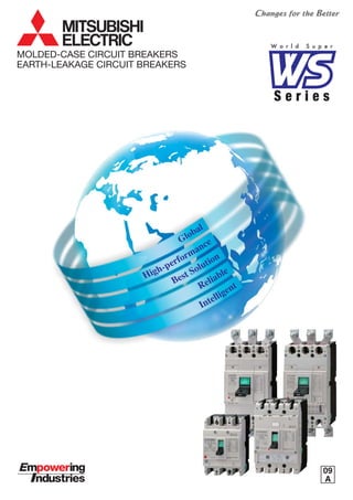
  • 1. S e r i e s W o r l d S u p e r MOLDED-CASE CIRCUIT BREAKERS EARTH-LEAKAGE CIRCUIT BREAKERS 09 A
  • 2. INDEX This material has been prepared for those who use the products for manufacturing assemblies, for holding electric works, for holding maintenance and for the others acquainted with electric expertise including those who operate the products (final users). Introduction 1........................................................................................................................................ Features 3.............................................................................................................................................. The Great Variable Accessories for Perfect Solution (Product Skeleton) 9..................................... 1. Series Configuration and List of Product Models 11...................................................................... Molded-Case Circuit Breakers Earth-Leakage Circuit Breakers Earth-Leakage Circuit Breakers for CE Marking Motor-Protection Breakers UL Listed Products Miniature Circuit Breakers ELRs and ZCTs Circuit Protectors ........................................................................................................................................ ...................................................................................................................................... ........................................................................................................... .............................................................................................................................................. .......................................................................................................................................................... ............................................................................................................................................... ................................................................................................................................................................. ............................................................................................................................................................. 13 21 25 29 30 31 35 37 2. Detailed Specifications 13................................................................................................................. 3. Special-purpose Breakers 38............................................................................................................ Mag Only (Instantaneous tripping circuit breakers) DC MCCBs and DSN Switches 400Hz MCCBs Low-Instantaneous MCCBs Generator-Protection MCCBs Measuring Display Unit (MDU) Breakers ............................................................................................................ ........................................................................................................................................ ................................................................................................................................................................... ............................................................................................................................................. ......................................................................................................................................... ........................................................................................................................ 38 38 39 39 39 40 1. Connection Types 2. Connection Accessories 3. Connection of Line and Load ...................................................................................................................................................................... ............................................................................................................................................................ ..................................................................................................................................................... 46 46 46 4. Connection Method 46......................................................................................................................
  • 3. 6 5 4 3 2 1 7 8 9 Internal Accessories 1. Accessories 2. Switch Operation and Rating 3. Maximum Number of Internally Mounted Accessories 4. Shunt Trip (SHT) 5. Undervoltage Trip (UVT) 6. Test Button Module (TBM) 7. Lead-wire Specifications 8. Internal Terminal (INT) 9. Vertical Lead-wire Terminal Block (SLT) 10. Pre-Alarm Module (PAL) 11. 3ø4W Neutral-pole protection Relay (NR) External Accessories 1. F-type Operating Handle (Breaker Mount Type) 2. V-type Operating Handle (Door Mount Type) 3. S-type Operating Handle 4. Terminal Cover 5. Electrical Operation Device 6. Mechanical Interlocks (MI) 7. Handle Lock Devices and Card Holder 8. IEC 35mm Rail Mounting Adapters ......................................................................................................................................................... ............................................................................................................................................................................... ..................................................................................................................................................... .............................................................................................................. ........................................................................................................................................................................ ............................................................................................................................................................. ......................................................................................................................................................... ............................................................................................................................................................ ................................................................................................................................................................ .................................................................................................................................... .......................................................................................................................................................... ............................................................................................................................... ....................................................................................................................................................... ......................................................................................................................... .............................................................................................................................. ............................................................................................................................................................ ........................................................................................................................................................................... ........................................................................................................................................................ ......................................................................................................................................................... ...................................................................................................................................... ............................................................................................................................................ 47 47 47 48 55 55 56 56 56 57 58 59 60 60 63 68 70 71 79 80 80 Molded-Case Circuit Breakers and Motor Breakers Earth-Leakage Circuit Breakers Earth-Leakage Circuit Breakers for CE Marking UL 489 Listed Molded-Case Circuit Breakers Miniature Circuit Breakers DIN Series Circuit Protectors ..................................................................................................... ................................................................................................................................... ......................................................................................................... .............................................................................................................. ............................................................................................................................................ ....................................................................................................................................................................... ........................................................................................................................................................... 81 117 141 161 173 177 181 Molded-Case Circuit Breakers Earth-Leakage Circuit Breakers ...................................................................................................................................... ................................................................................................................................... 183 183 Caution The manual covers the product specifications for selecting an appropriate low-voltage breaker. There is the “HANDLING AND MAINTENANCE” describing how to handle the products. To use the products, separately request the “HANDLING AND MAINTENANCE”, for correct operation. 5. Accessories 47................................................................................................................................... 6. Characteristics and Dimensions 81.................................................................................................. 7. Ordering Information (http://www.MitsubishiElectric.co.jp/haisei/lvs/) 183................................................................................................................... 8. Melshort 2 184.................................................................................................................................... 9. Low-voltage switchgear Technical information service via the internet (A Smarter, Easier Way to Select Breakers) 185..............................
  • 4. 1 1 Full range of MITS (30A to 16 GloGlo Compliance with w S e r i e s W o r l d S u p e r ASTA TPC TUV CCC LR GL BV NKDNV ABS SABS JIS GB EN IEC CCS New Digital ETR High-PerformanceHigh-Performance Downsizing of 630AF, New Digital ETR Volume 60% downsized 210 275 140 257 Previous New 0.01 0.1 1 10 1 x 10² 1 x 10³ 1 x 10⁴ Current (A) Time(s) Ir Current setting Is Short-delay tripping current TL High-voltage fuse- Allowable short-time characteristics Long-delay operating time Short-delay operating timeTs Ii Instantaneous tripping current Current-converted value on the high-voltage side Ip Pre-alarm current Load current High voltage Low voltage Transformer NFB (electronic) M Load Switch with fuse 250AF (Type“SGW, HGW, RGW, UGW”) Product Skelton Best SolutionBest Solution Plenty of accessories, Easy installation 24 23 22 16 17 18 19 20 21 7 745 11 12 13 8 6 9 15 398 1312 2 10 1110 1 14
  • 5. 2 UBISHI WS Series 00A frame) obalbal orldwide standards CSA UL Mechanism Terminal Internal Accessories External Accessories Breaking PerformanceRelay Shunt-less Advanced ISTAC PA Auto-Puffer JPT ReliableReliable High reliability, Best performance IntelligentIntelligent Measuring and communicating Personal Computer MELSECNET/10 Interface card MELSECNET/10 Interface Unit MDU Eco Monitor Pro ME96NSR AE-SW PLC I/O Unit CC-Link® By using various application software for PLC, users can also connect to the network SCADA system.
  • 6. Global Compliance with worldwide standards 3 ASTA TPC TUV CCC LR GL BV NKDNV ABS SABS CSA UL JIS GB EN IEC CCS WS Series International Standard Conformance List Standards IEC JIS EN International Japan Europe GB China UL CSA LR GL DNV ABS BV NK USA Canada Safety Certification Marine Approvals UK Germany Norway USA France Japan CCS China • Compliance with worldwide standards (IEC/JIS/EN/GB/UL/CSA) • Applicable to marine approvals • New design with Laser Marking • All products with lsolation function • RoHS compliance S e r i e s W o r l d S u p e r ■ Full range of WS Series (up to 1600AF) NF-C NF-S NF-H NF-U NV-C NV-S NV-H NV-U MCCB ELCB AF 125 250 400 630 800 1250 160010001606332(30) NF30-CS NF32-SW NV30-CS NV32-SW NF63-CW NF63-SW NF63-HW NV63-CW NV63-SW NV63-HW NF125-CW NF125-SW NF125-SGW NF125-HW NF125-HGW NF125-RGW NF125-UGW NV125-CW NV125-SW NV125-HW NV125-RW NF160-SW NF160-SGW NF160-HW NF160-HGW NF250-CW NF250-SW NF250-SGW NF250-HW NF250-HGW NF250-RGW NF250-UGW NV250-CW NV250-SW NV250-SEW NV250-HW NV250-HEW NV250-RW NF400-CW NF400-SW NF400-SEW NF400-HEW NF400-REW NF400-UEW NV400-CW NV400-SW NV400-SEW NV400-HEW NV400-REW NF630-CW NF630-SW NF630-SEW NF630-HEW NF630-REW NV630-CW NV630-SW NV630-SEW NV630-HEW NF800-CEW NF800-SEW NF800-SDW NF800-HEW NF800-REW NF800-UEW NV800-SEW NV800-HEW NF1000-SEW NF1250-SEW NF1250-SDW NF1600-SEW NF1600-SDW NF250-SGW 3P ✽ RoHS…The Restriction of the use of certain Hazardous Substances in Electrical and Electronic Equipment
  • 7. High-Performance Downsizing, New Digital ETR S e r i e s W o r l d S u p e r 4 0.01 0.1 1 10 1 x 10² 1 x 10³ 1 x 10⁴ Ir Current setting Is Short-delay tripping current Current (A) Time(s) 0.01 0.1 1 10 1 x 10² 1 x 10³ 1 x 10⁴ Current (A) Time(s) Ir Current setting Is Short-delay tripping current TL High-voltage fuse- Allowable short-time characteristics Long-delay operating time Short-delay operating timeTs Ii Instantaneous tripping current Current-converted value on the high-voltage side Ip Pre-alarm current Load current High voltage Low voltage Transformer NFB (electronic) M Load Switch with fuse ● 630AF models downsized to the size of 400AF model, contributing to compact panels and simplification of design. ● MCCB-AC/DC common use (excl. Electronic trip type) 3-pole:available up to 400VDC, 4-pole:available up to 500VDC (NF400-SW, NF630-SW) ● Improved breaking capacity at 690VAC (NF400-HEW, NF630-HEW) ■ 400AF, 630AF & 800AF models easier to use ● Installed digital ETR same as Electronic relay for under 800AF • Multi adjustment available (Long time delay, short time delay, Instantaneous, pre-alarm characteristics):easier coordination with upper breakers. • Pre-alarm equipped as Standard:LED turned on when load current exceeds pre-alarm setting current. • Suitable for use as a main breaker:isolation comformity to IEC Standard. ■ NEW Digital ETR (Electronic Trip Relay) for NF1000-SEW, NF1250-SEW & NF1600-SEW Volume 60% downsized 210 275 Previous Icu/Ics 15/15 kA New 35/18 kA Icu/Ics 140 257 Previous New Previous Icu/Ics 45/45 kA New 50/50 kA Icu/Ics ● Improved breaking capacity at 400/415VAC (NF400-SEW, NF630-SW/SEW, NF800-SEW) Previous New Rated current Short time-delay tripping current Instantaneous tripping currentCurrent setting Short time-delay operating time Pre-alarm current Long time-delay operating time
  • 8. • Isolation suitability • Class ll insulation • Increased operating cycles • Increased lcu • High voltage • Ics=100% lcu Relay Mechanism Internal Accessories External Accessories Breaking Performance ■ Technology for WS Series • Cassette-type accessories • Wide range of Rated Voltage Shunt-less JPT Advanced ISTAC PA Auto-Puffer Polymer Ablation type Auto-Puffer [Adopted on SGW, HGW, RGW, UGW] Advanced Impulsive Slot-Type Accelerator [Adopted on SGW,HGW, RGW, UGW ] Jet Pressure Trip Mechanism [Adopted on SGW, HGW, RGW, UGW] • IP20 Mold-cover Finger protection • Front compression terminal ⇔ Box terminal ⇔ Rear ⇔ PM • Electric operators ➀ High speed type ➁ Isolation suitability • IP20 PM with Safety Device • Handle Lock Device • F/V handle • IP40 Terminal cover • Relay-unit Thermal type & Electronic type • AC/DC common use • Thermal adjustable range is expanded. Terminal Shunt-less Current Flow Technology [Adopted on SGW, HGW, RGW, UGW] Double plates conductors hold the movable conductor without flexible wires. This shunt-less structure achieves the increased operating cycles. [PA Auto-Puffer] [JPT] [Advanced ISTAC] [Shunt-less] Endurance (C-O cycles) (times) 50,000 40,000 30,000 20,000 10,000 0 Electrical Mechanical NF125-SGW/HGW NF160-SGW/HGW NF250-SGW/HGW Holder Movable contact Movable contact revolving shaft Spring During revolution the movable contact is constantly in contact with the holder, maintaining current flow. Reliable High reliability, Best performance 5
  • 9. ■ Best performance of SGW / HGW / RGW / UGW ■ 2 types of Relay for SGW / HGW / RGW / UGW 85 100 125 200 200 200 200 200 200 125 125 125 125 125 36 75 75 70 65 50 20 25 30 36 36 36 30 8 Series Breaking Capacity lcu/lcs 200 150 100 50 0 (kA) 230VAC 380VAC 400VAC 415VAC 440VAC 500VAC 690VAC U(UGW) R(RGW) S(SGW) H(HGW) Max.let-through peak current (kA) (400VAC) Max.peakcurrent(kA) Short-Circuit Current, sym.r.m.s.(kA) Prospective short-circuit current asym. peak NF250-HGW NF250-UGW 200 100 80 60 40 20 10 8 6 4 2 1 1 2 4 6 8 10 20 40 60 80 100 200 I2 t let-through characteristics (400VAC) MAX.I2 t(A2 •s) Short-Circuit Current, sym.r.m.s.(kA) 10 8 6 4 2 1 0.8 0.6 0.4 0.2 0.1 0.08 0.06 0.04 1 2 4 6 8 10 20 40 60 80 100 200 NF250-HGW NF250-UGW (✕106 ) T lr li l li(DC)=1.3Xli(AC) li(X250AAC) 4 10 160 200 2506 8 lr lr(A)li MODEL RT 250 ln 250 A 50/60Hz MADE IN JAPAN LN326N433-13P3E Thermal Adjustable Relay NF250-SGW/HGW NF160-SGW/HGW NF125-SGW/HGW Hi Lo Rating ln(A) 25 40 63 100 125 160 250 Type Overload Protection (Thermal) Short-Circuit Protection (Magnetic) Tripping threshold lr (A) Neutral protection (✽1) 4P3E 4P4E 16-25 25-40 40-63 63-100 80-125 125-160 160-250 No Protection 1 ✕ lr Tripping threshold li Fixed 10✕ln (AC), 13✕ln (DC) Adjustable 4 to 10✕ln (AC), 5.2 to 13✕ln(DC) Note (✽1) The type 4P3E is standard. If the type 4P4E is required, specify the type 4P4E separately and explicitly. lr li l lp ls Ts TL T Electronic Relay LN326N429-11 MADE IN JAPAN MODEL RE250 AC only Ir 125 160 200 250 12 60 80 100 2 3 4 5 6 7 8 10 0.6 1 2 T I Ip TL Is Ts Ii Ir 3 4 7 7.5 8.5 9.5 4P3E 4P4E8 9 10 6 8 10 12 14 2.5 3.5 (A) L(s) (XIr)T Is (s)Ts (X250A)Ii (XIr)Ip pNITEST ln 250 A 50/60Hz OVERPAL70% Hi Lo Rating Type ln(A) (40C) 32 63 100 125 160 250 NF250-SGW/HGW NF160-SGW/HGW NF125-SGW/HGW Overload Protection Short-Circuit Protection Pre-Alarm (for Indication) Indicator (LED) Tripping threshold lr (A) LTD Tripping time TL(s) Neutral protection (Slectable) 16-32 32-63 63-100 75-125 80-160 125-250 12-60-80-100 step adjustable (at 2 ✕ lr) 0-1 ✕ lr (Step adjustable) STD PAL INST Pickup current ls Tripping time Ts(s) Tripping threshold li 2-2.5-3-3.5-4-5-6-7-8-10 ✕ lr step adjustable 0.06-0.1-0.2-0.3 step adjustable (at 1.5 ✕ ls) 4 to 14 ✕ ln continuous adjustable Pickup current lp Operating time Tp 0.7-0.75-0.8-0.85-0.9-0.95-1.0 ✕ lr step adjustable TL/2 70%-LED (green) PAL-LED (orange) Over-LED (red) Lights at 0.7 ✕ lr Flashs at lp and Lights at over Tp Lights at 1.15 ✕ lr Thermal type unit Electronic type unit S e r i e s W o r l d S u p e r 6
  • 10. 7 Best Solution Abundant Accessories and Easy Installation High-speed Motor Device Motor devices for 125-250AF are now easier to use,contributing to simple installation. ✽ A spring charge mechanism has been adopted for high-speed operation. (0.05~0.1sec) ✽ Installation is fast and simple, only requiring two screws. External Handle A safer and easy-to-operate handle has been adopted. ✽ Complies with IP65 protection rating standards. ✽ Isolation function achieved through combination with the breaker unit. ✽ Structured to allow relay adjustments after installation as well. ✽ Equipped with a cylinder key (optional) to prevent misuse. IP-20PM with Safety Device [Adopted for SGW, HGW] Specialized for 3- and 4-pole use (incompatible with 2-pole use). ✽ Complies with IP-20 protection rating standards. ✽ A safety device is optional. ✽ Connectable with up to nine leads (for PLT). ✽ Can be modified from front to rear connection. (Note: Modification by users is not authorized) IP20: Finger protection. The adoption of cassette-type internal accessories simplifies use, and the common use of different voltages realizes a major reduction in the number of types. Additionally, UVTs are now available for ELCBs and time delay types have been expanded, offering a wider range of applications. ✽ Cassette-type Accessories Giving greater flexibility when upgrading circuits, cassette-type accessories make ordering easy and enable simple, one-touch installation. Insulation also improves safety. Compatible with all breaker series The alarm switch (AL), auxiliary switch (AX), shunt trip (SHT), and undervoltage trip (UVT) all come as cassette-type accessories compatible with all breaker series. (IP-20PM) 3-way Lead Wire (adjustable) Vertical lead wire terminal block (SHT) Lead wire to line side Flying lead wire 1.Push the trip button (PTT) 2.Loosen the front cover screws 3.Open the front cover 4.Install the accessories 5.Close the front cover and tighten the screws. Power Supply Module V-Handle Previous models WS Series (New) UVT voltage SHT voltage VAC VDC VAC VDC (24), (48), 100-120, 200-240, 380-450, (440-550) (12), (24), (36), (48), 100, (110), (125), (220) 100-110, (100-120), 200-220, (220-240), (380-415), 400-440, (440-480), (500-550) (24), (48), 100, (110) 24-48, 100-240, 380-550 12, 24-36, 36-48, 100-125, 220-250 24/48, 100-110/120-130, 200-220/230-250, 380-415/440-480, 500-550/690 24/48, 100/110, 110/125 Internal Accessories External Accessories
  • 11. 8 Intelligent Measuring and Communicating S e r i e s W o r l d S u p e r Product Design Simplifies Use & Expands Applications IP20 Terminal Connection Safety of connections has been increased for SGW and HGW. ✽ Protection rating of IP20 as standard is ensured. Connection Flexibility Compatible with various connection methods. Solderless terminals are now built into the breaker design the conventional style where terminals are affixed on the outside. Maximum connecting cable size of 185mm2 (SGW/HGW). (Note: Certain models have externally attached terminals.) Handle Locks With the WS Series, ON/OFF locking is possible with the use of a padlock. Up to three padlocks may be attached. ✽ Customers are requested to use their own padlocks. Terminal Cover Major improvements have been achieved in front connection terminal safety. ✽ With terminal covers, a protection rating of IP40 is ensured. (“SGW, HGW, RGW, UGW”) IEC Rail Mounting for 32, 63AF Installation hooks are included for 32,63AF, markedly simplifying installation work. OFF lock with 3 padlocks (“SGW, HGW, RGW, UGW”) ON lock OFF lock Personal computer MELSECNET/10 interface card MELSECNET/10 Interface unit MDU Eco Monitor Pro ME96NSR AE-SW PLC I/O unit CC-Link® By using various application software for PLCs, users can also connect to the SCADA system. • MDU (Measuring Display Unit) with NF 250-800AF • Compact, white measuring unit • Measuring data can be transmitted to a PC or a PLC through CC-Link • AL / AX with CC-Link transmission • Improved accuracy(electric current): ±2.5% of rated value → ±2.5% of true value
  • 13. S e r i e s W o r l d S u p e r 10 7 7 11 12 13 8 6 9 15 398 1312 2 11 1 14 MCCB Relay unit (Thermal type) (RT) (✽1) Relay unit (Electronic type) (RE) (✽1) Relay unit (Magnetic only type) (RM) (✽1) Relay unit (Switch-disconnector type) (✽1) Super current-limiting unit* Solderless (BOX) terminals Front connection nuts Rear connections Insulating barrier (BA-F) Small terminal cover (TC-S) Large terminal cover (TC-L) Rear terminal cover (BTC) Plug-in base (PM) Connections for Plug-in Mechanical interlock device (MI) OFF Lock with 3 Padlock (HLF3) Handle lock device (LC/HLF/HLN/HLS) (F-type operating handle) (V-type operating handle) Electrical operation device (MD) Alarm/Auxiliary switch device (AL/AX) Under voltage trip device (UVT) Shunt trip device (SHT) 1 2 3 4 5 6 7 8 9 10 11 12 13 14 15 16 17 18 19 20 21 22 23 24 Note (✽1) All the accessories are field mounting type except No.2, 3, 4, 5 and 6.
  • 14. Series Configuration Molded-case circuit breakers Earth-leakage circuit breakers NF-C Economy type NF-S Standard type NF-H High-performance type NF-U Current limiting-type ultra breaker NV-C Economy type NV-S Standard type NV-H High-performance type NV-U Ultra current-limiting type MB Motor breaker Motor-protection breakers NEMA-type for consumer unit DIN-series for general consumer unit Miniature circuit breakers BH BH-P BH-S BH-PS BH-D6 BH-DN BV-D BV-DN KB-D For equipment Circuit protectors CP30-BA CP-B CP-S 11 1. Series Configuration and List of Product Models
  • 15. 1 50 100 150 225 250 400 600 UL489 Listed Molded-case circuit breaker NF50-SWU NF100-CWU NF-SFW NF225-CWU NF-SKW NF-SLW NF100-SWU Earth-leakage protector UL489 Listed Molded-case circuit breaker NV50-SWU NV100-SWU Series Frame A UL listed products NF-UL UL489 Listed Molded-case circuit breaker NV-UL Earth-leakage protector UL489 Listed Molded-case circuit breaker Miniature Circuit Breakers ULlisted products AF BH 60 100 BH BH-P BH-S — BH-PS — DIN Series AF MCB RCCB Isolating switch BH-DN BH-D6 BV-D RCBO BV-DN KB-D 63 and less Circuit Protectors AF CP CP30-BA CP-B CP-S 30 and less Details will be available upon request.( ) Details will be available upon request.( ) 32 (30) 63 125 (100) 250 400 630 800 1000 1600 NF-C Economy type NF30-CS NF63-CW NF125-CW NF250-CW NF400-CW NF630-CW NF-S Standard type NF-H High-performance type NF32-SW NF63-SW NF125-SW NF250-SW NF400-SW NF630-SW NF800-SDW NF1000-SEW NF1250-SEW NF1250-SDW NF1600-SEW NF1600-SDWNF125-SGW NF250-SGW NF400-SEW NF630-SEW NF800-SEW NF63-HW NF125-HW NF250-HW NF400-HEW NF630-HEW NF800-HEW NF125-HGW NF250-HGW 160 NF160-SW NF160-SGW NF160-HW NF160-HGW NF400-REW NF630-REW NF800-REW NF-U Ultra current-limiting type NF125-RGW NF250-RGW NF400-UEW NF800-UEW NF125-UGW NF250-UGW NV-C Economy type NV30-CS NV125-CW NV125-CW NV250-CW NV400-CW NV630-CWNV63-CW NV63-CW NV-S Standard type NV-H High-performance type NV32-SW NV32-SW NV63-SW NV63-SW NV125-SW NV125-SW NV250-SW NV400-SW NV630-SW NV800-SEW NV250-SEW NV63-HW NV63-HW NV125-HW NV125-HW NV250-HW NV400-HEW NV250-HEW NV400-REW NV-U Ultra current-limiting type NV125-RW NV125-RW NV250-RW MB Motor breaker MB100-SW MB225-SW MB30-SW MB30-CS MB50-CW MB50-SW Series Frame A List of Product Models Molded-casecircuitbreakersEarth-leakagecircuitbreakersEarth-leakagecircuitbreakersforCEMarkingMotor-protection breakers 1250 NV-C Economy type NV-S Standard type NV-H High-performance type NV-U Ultra current-limiting type NV-SKWNV225-CWU NV400-SEW NV630-SEW NV800-HEWNV630-HEW NV250-CW NV400-CW NV630-CW NV250-SW NV400-SW NV630-SW NV800-SEW NV250-HW NV400-HEW NV400-REW NV250-RW NV400-SEW NV630-SEW NV800-HEWNV630-HEW NF-SJW NF-HJW NF800-CEW 12
  • 16. Series Frame Size Image Type name Rated current in (Amp.) Rated ambient temperature (°C) Number of poles Rated insulation voltage Ui (V) Rated short-circuit breaking capacities (kA) IEC 60947-2 (Icu/Ics) AC (50/60Hz) 690V 525V 500V 440V 415V 400V 380V DC 230V 250V 300V Utilization category Reverse connection (terminals unmarked) Rated impulse withstand voltage Uimp (kV) Pollution degree Number of operating cycles without current with current 440V-In/2 440V-In 690V-In/2 690V-In Overall dimensions (mm) a b c ca Installation and connections Fixed Front Screw terminal Synchronous Closing (UVT-S) Non-Synchronous Closing (UVT-N) Solderless (box) terminal (SL) Rear (B) Busbar terminal Plug-in Rear (PM) Rear/front IP20 (PM-IP) IEC 35mm rail Mounting hook (option) Adapter (option) Cassette-type accessories (option) (✽5) Alarm switch (AL) Auxiliary switch (AX) Shunt trip (SHT) Undervoltage trip (UVT) Accessorie’s connection (option) with Lead-wire terminal block (SLT) with Internal terminal type (INT) with Flying leads Built-in accessories (option) Pre-alarm (contact output) (✽3) (PAL) Overcurrent trip alarm (✽3) (OAL) Enclosure Dustproof (S) (I) Handle lock (HL) (HL-S) External accessories (option) Marine approval Electrical operation device (MD) Mechanical interlock Handle lock device (MI) Lock cover (LC) Waterproof (W) External operating handle Mounted on breaker (V) (S) Door mounting (F) Insulating barrier Between phase (BA-F) To ground (BA-G) Terminal cover Large (TC-L) Small (TC-S) for rear connection (BTC) for plug-in (PTC) L/R G/L BV DNV ABS Automatic tripping device Trip button Note (✽1) Use two poles for three- and four-pole products. If wired as shown on the right, three and four poles can be used for up to 400VDC and 500VDC, respectively. (✽2) Use two poles for three- and four-pole products. If wired as shown on the right, three and four poles can be used for up to 500VDC and 600VDC, respectively. (✽3) PAL and OAL are not available together. Only one can be specified. (✽4) Specify if for DC use. (✽5) Cassette-type accessories are not compatible with NF30-CS. a ca c b Suitability for isolation Mass of front-face type (kg) Transparent (TTC) C Series 30 NF30-CS 3 5 10 15 20 30 40 2 3 45 67.5 500 – – – 1.5/1.5 1.5/1.5 – 1.5/1.5 2.5/2 (240V) – – – A – 4 2 10,000 6,000 (415V) – – 96 52 67 – – – – – ● – – – – – – – – – – ● – – – – – – – – – – Hydraulic- magnetic – 0.25 0.35 ● ● ● ● ● ● ● ● ● ● ● ● ● ● 6,000 (415V) S Series C Series C SeriesS Series 32 NF32-SW 3 4 (5) 6 10 (15) 16 20 25 (30) 32 40 2 3 2.5/1 (✽4) – 600 – – 2.5/1 2.5/1 2.5/1 5/2 5/2 7.5/4 – A 6 2 10,000 6,000 6,000 – – 130 68 90 – – – – – – – – – Hydraulic- magnetic Equipped 50 75 – 0.4 0.55 ● ● ● ● ● ● ● ● ● ● ● ● ● ● ● ● ● ● ● ● ● ● ● ● ● ● ● ● ● ● ● ● ● ● 63 NF63-CW 3 4 (5) 6 10 (15) 16 20 25 (30) 32 40 50 (60) 63 40 2 3 2.5/1 (✽4) – 50 75 600 – – 2.5/1 2.5/1 2.5/1 5/2 5/2 7.5/4 – A 6 2 10,000 6,000 6,000 – – 130 68 90 – – – – – – – – – Hydraulic- magnetic Equipped – 0.45 0.6 ● ● ● ● ● ● ● ● ● ● ● ● ● ● ● ● ● ● ● ● ● ● ● ● ● ● ● ● ● ● ● ● ● ● 63 NF63-SW 3 4 (5) 6 10 (15) 16 20 25 (30) 32 40 50 (60) 63 40 2 3 4 600 – – 7.5/4 7.5/4 7.5/4 7.5/4 7.5/4 15/8 – A 6 2 15,000 15,000 8,000 – – 130 68 90 – – – – – – – – – Hydraulic- magnetic Equipped 7.5/4 (✽4) – 50 75 100 0.45 0.6 0.7 – – –– – – – – – ● ● ● ● ● ● ● ● ● ● ● ● ● ● ● ● ● ● ● ● ● ● ● ● ● ● ● ● ● ● ● ● ● ● ● ● ● ● ● ● ● ● ● ● ● ● ● ● ● ● ● ● ● ● ● ● ● ● ● ● ● ● ● ● ● ● ● ● H Series 63 NF63-HW 10 (15) 16 20 25 (30) 32 40 50 (60) 63 40 690 2.5/1 – 7.5/4 10/5 10/5 10/5 10/5 25/13 – A 6 2 15,000 15,000 8,000 – -– 130 68 90 – – – – – – – – – Hydraulic- magnetic Equipped 7.5/4 (✽4) – 50 75 100 0.45 0.6 0.7 – – –– – – – – – 432 125 NF125-CW 50 (60) 63 (75) 80 100 125 40 2 3 7.5/4 (✽1) 60 90 600 – – 7.5/4 10/5 10/5 10/5 10/5 30/15 – A 8 3 10,000 6,000 6,000 – – 130 68 90 – – – – – – Thermal- magnetic Equipped 0.65 0.9 – – ● ● ● ● ● ● ● ● ● ● ● ● ● ● ● ● ● ● ● ● ● ● ● ● ● ● ● ● ● ● ● ● ● ● ● ● ● 3-pole 4-pole Line Load Load Line 2. Detailed Specifications Molded-Case Circuit Breakers 13
  • 17. 2 ● ● ● ● ● ● ● ● ● ● ● ● ● ● ● ● ● ● ● ● ● ● ● ● ● ● ● ● ● ● ● ● ● ● ● ● ● S Series NF125-SW (15) 16 20 (30) 32 40 50 (60) 63 (75) 80 100 125 40 690 8/4 18/5 18/9 25/13 30/15 30/15 30/15 50/25 – A 8 3 25,000 20,000 10,000 1,000 1,000 130 68 90 – – – – – – Thermal- magnetic Equipped 125 15/8 (✽1) 60 0.7 90 120 0.95 1.3 – – – – – – – – – – 432 – ● ● ● ● ● ● ● ● ● ● ● ● ● ● ● ● ● ● ● ● ● ● ● ● ● ● ● ● ● ● ● ● ● ● ● ● ● ● ● ● ●● ●● ● ● ● ● ● ● ● ● ● ● ● ● ● ● ● ● ● ● ● ● ● ● ● ● NF125-SGW RT 16–25 25–40 40–63 63–100 80–125 40 – 690 8/8 22/22 30/30 36/36 36/36 36/36 36/36 85/85 A 8 3 50,000 40,000 30,000 1,000 1,000 165 86 110 – – – – – – – – – ● – Thermal- magnetic Equipped NF125-SGW RE 16–32 32–63 63–100 75–125 40 3 4 690 8/8 22/22 30/30 36/36 36/36 36/36 36/36 85/85 – – A 8 3 50,000 40,000 30,000 1,000 1,000 165 86 110 – – – – – ● – Electronic Equipped 105 140 2.0 2.6 105 140 2.0 2.6 – – – – 432 20/20 (✽2) ● ● ● ● ● ● ● ● ● ● ● ● ● ● ● ● ● ● ● ● ● ● ● ● ● ● ● ● ● ● ● ● ● ● ● ● ● NF125-HW (15) 16 20 (30) 32 40 50 (60) 63 (75) 80 100 40 690 10/5 22/11 30/15 50/25 50/25 50/25 50/25 100/50 – A 8 3 25,000 20,000 10,000 1,000 1,000 130 68 90 – – – – – – Thermal- magnetic Equipped 40/20 (✽1) 0.8 0.95 90 120 1.3 – – – – – – – – – – 432 – ● ● ● ● ● ● ● ● ● ● ● ● ● ● ● ● ● ● ● ● ● ● ● ● ● ● ● ● ● ● ● ● ● ● ● ● ● ● ● ● ● ● ●● ●● ● ● ● ● ● ● ● ● ● ● ● ● ● ● ● ● ● ● ● ● ● ● H Series – Electronic 125 NF125-HGW RT 16–25 25–40 40–63 63–100 80–125 40 690 20/20 35/35 50/50 65/65 70/70 75/75 75/75 100/100 A 8 3 50,000 40,000 30,000 1,000 1,000 165 86 110 – – – – – – – ● – Thermal- magnetic Equipped NF125-HGW RE 16–32 32–63 63–100 75–125 40 3 4 690 20/20 35/35 50/50 65/65 70/70 75/75 75/75 100/100 – – A 8 3 50,000 40,000 30,000 1,000 1,000 165 86 110 – – – – – ● – Equipped 105 140 2.0 2.6 105 140 2.0 2.6 – – – – – – 432 40/40 (✽2) U Series NF125-RGW RT 16–25 25–40 40–63 63–100 40 2 3 690 25/25 125/125 125/125 125/125 125/125 125/125 125/125 125/125 – A 8 3 50,000 40,000 30,000 1,000 1,000 240 105 3.1 86 110 – – – – – – – ● ● – Equipped NF125-UGW RT 16–25 25–40 40–63 63–100 40 690 30/30 200/200 200/200 200/200 200/200 200/200 200/200 200/200 A 8 3 50,000 40,000 30,000 1,000 1,000 240 86 110 – – – – – – – ● ● – Thermal- magnetic Thermal- magnetic Equipped 125 – – – 105 140 3.1 3.9 – – – – – – – – – – – – 432 ● ● ● ● ● ● ● ● ● ● ● ●● ● ● ● ● ● ● ● ● ● ● ● ● ● ● ● ● ● ● ● ● ● ● ● ● ● ● ● ● ● ● ● ● ● ● ● ● ● ● ● ● ● ● ● ● ● ● ● 14
  • 18. Series Frame Size Image Type name Rated current In (Amp.) Rated ambient temperature (°C) Number of poles Rated insulation voltage Ui (V) Rated short-circuit breaking capacities (kA) IEC 60947-2 (Icu/Ics) AC (50/60Hz) 690V 525V 500V 440V 415V 400V 380V DC 230V 250V 300V Utilization category Reverse connection (terminals unmarked) Rated impulse withstand voltage Uimp (kV) Pollution degree Number of operating cycles without current with current 440V-In/2 440V-In 690V-In/2 690V-In Overall dimensions (mm) a b c ca Installation and connections Fixed Front Screw terminal Synchronous Closing (UVT-S) Non-Synchronous Closing (UVT-N) Solderless (box) terminal (SL) Rear (B) Busbar terminal Plug-in Rear (PM) Rear/front IP20 (PM-IP) IEC 35mm rail Mounting hook (option) Adapter (option) Cassette-type accessories (option) Alarm switch (AL) Auxiliary switch (AX) Shunt trip (SHT) Undervoltage trip (UVT) Accessorie’s connection (option) with Lead-wire terminal block (SLT) with Internal terminal type (INT) with Flying leads Built-in accessories (option) Pre-alarm (contact output) (✽3) (PAL) Overcurrent trip alarm (✽3) (OAL) Enclosure Dustproof (S) (I) Handle lock (HL) (HL-S) External accessories (option) Marine approval Electrical operation device (MD) Mechanical interlock Handle lock device (MI) Lock cover (LC) Waterproof (W) External operating handle Mounted on breaker (V) (S) Door mounting (F) Insulating barrier Between phase (BA-F) To ground (BA-G) Terminal cover Large (TC-L) Small (TC-S) for rear connection (BTC) for plug-in (PTC) L/R G/L BV DNV ABS Automatic tripping device Trip button Note (✽1) Use two poles for three- and four-pole products. If wired as shown on the right, three and four poles can be used for up to 400VDC and 500VDC, respectively. (✽2) Use two poles for three- and four-pole products. If wired as shown on the right, three and four poles can be used for up to 500VDC and 600VDC, respectively. (✽3) PAL and OAL are not available together. Only one can be specified. a ca c b Suitability for isolation Mass of front-face type (kg) Transparent (TTC) ● ● ● ● ● ● ● ● ● ● ● ● ● ● ● ● ● ● ● ● ● ● ● ● ● ● ● ● ● ● ● ● ● ● ● ● ● ● ● ● ● ● ● ● – ● ● ● ● ● ● ● ● ● ● ● ● ● ● ● ● ● ● ● ● ● ● ● ● ● ● ● ● ● ● ● ● ● ● ● ● ● ● ● ● ● ● ● ● S Series Electronic NF160-SW 125 150 160 40 690 – – 15/8 25/13 30/15 30/15 30/15 50/25 – A 6 2 12,000 4,000 4,000 – – 165 68 92 – – – – – – – – Thermal- magnetic Equipped 160 NF160-SGW RT 125–160 40 690 8/8 22/22 30/30 36/36 36/36 36/36 36/36 85/85 – A 8 3 40,000 30,000 20,000 1,000 1,000 165 86 110 – – – – – – – ● – Thermal- magnetic Equipped NF160-SGW RE 80–160 40 3 4 690 8/8 22/22 30/30 36/36 36/36 36/36 36/36 85/85 – – A 8 3 40,000 30,000 20,000 1,000 1,000 165 86 110 – – – – – ● – Equipped 15/8 (✽1) 105 140 105 140 105 140 2.0 2.6 2.0 2.6 – – – – – – – – – – – – – – – – – – – – – – – 432 1.91.51.3 432 20/20 (✽2) H Series NF160-HW 125 150 160 40 690 5/3 – 30/8 50/13 50/13 50/13 50/13 100/25 – A 6 2 12,000 4,000 4,000 1,000 1,000 165 68 92 – – – – – – – – – Thermal- magnetic Equipped 160 NF160-HGW RT 125–160 40 690 20/20 35/35 50/50 65/65 70/70 75/75 75/75 100/100 – A 8 3 40,000 30,000 20,000 1,000 1,000 165 86 110 – – – – – – – ● – Thermal- magnetic Equipped NF160-HGW RE 80–160 40 690 20/20 35/35 50/50 65/65 70/70 75/75 75/75 100/100 – – A 8 3 40,000 30,000 20,000 1,000 1,000 165 86 110 – – – – – ● – Electronic Equipped 3 4 105 140 2.0 2.6 2 3 4 1.3 1.5 1.9 2 3 4 40/20 (✽1) 40/40 (✽2) 105 140 105 140 2.0 2.6 – – – – – – – – – – – – – – – – – – – – – – – ● ● ● ● ● ● ● ● ● ● ● ● ● ● ● ● ● ● ● ● ● ● ● ● ● ● ● ● ● ● ●● ● ● ● ● ● ● ● ● ● ● ● ● ● ● ● ● ● ● ● ● ● ● ● ● ● ● ● ● ● ● ● ● ● ● ● ● ● ● ● ● ● ● ● ● ● ● ● ● ● ● ● ● ● ● ● 3-pole 4-pole Line Load Load Line 2. Detailed Specifications Molded-Case Circuit Breakers 15
  • 19. 2 C Series S Series H Series U Series 3 4 3 4 NF250-SW (100) 125 150 175 200 225 250 40 690 – – 15/8 25/13 30/15 30/15 30/15 50/25 – A 6 2 12,000 4,000 4,000 – -– 165 68 92 – – – – – – – – Thermal- magnetic Equipped 105 140 2.0 2.6 105 140 2.0 2.6 250 NF250-SGW RT 125–160 160–250 40 690 8/8 22/22 30/30 36/36 36/36 36/36 36/36 85/85 – A 8 3 25,000 15,000 10,000 1,000 1,000 165 86 110 – – – – – – – ● – Thermal- magnetic Equipped NF250-SGW RE 125–250 40 690 8/8 22/22 30/30 36/36 36/36 36/36 36/36 85/85 – – A 8 3 25,000 15,000 10,000 1,000 1,000 165 86 110 – – – – – ● ● – Electronic Equipped NF250-HW 125 150 175 200 225 250 40 690 5/3 – 30/8 50/13 50/13 50/13 50/13 100/25 – A 6 2 12,000 4,000 4,000 1,000 1,000 165 68 92 – – – – – – – – Thermal- magnetic Equipped NF250-HGW RT 125–160 160–250 40 690 20/20 35/35 50/50 65/65 70/70 75/75 75/75 100/100 – A 8 3 25,000 15,000 10,000 1,000 1,000 165 86 110 – – – – – – – ● – Thermal- magnetic Equipped 250 NF250-HGW RE 125–250 40 – 690 20/20 35/35 50/50 65/65 70/70 75/75 75/75 100/100 – A 8 3 25,000 15,000 10,000 1,000 1,000 165 86 110 – – – – – ● – Electronic Equipped 105 3.1 2 3 250 NF250-RGW RT 125–160 160–225 40 690 25/25 125/125 125/125 125/125 125/125 125/125 125/125 125/125 – A 8 3 25,000 15,000 10,000 1,000 1,000 240 86 110 – – – – – – – – ● – ● Thermal- magnetic Thermal- magnetic Equipped NF250-UGW RT 125–160 160–225 40 690 30/30 – 200/200 200/200 200/200 200/200 200/200 200/200 – A 8 3 25,000 15,000 10,000 1,000 1,000 240 86 110 – – – – – – – – ● – Equipped 2 3 42 3 4 1.3 1.5 1.9 15/8 (✽1) 20/20 (✽2) 40/40 (✽2) 40/20 (✽1) – 105 140 105 140 2.0 2.6 105 140 105 140 2.0 2.6 105 140 3.1 3.9 – – – – – – – – – – – – – – – – – – – – – – – – – – – – – – – – – – – – – – – – – – – – – 432 1.91.51.3 432 432 ● ● ● ● ● ● ● ● ● ● ● ● ● ● ● ● ● ● ● ● ● ● ● ● ● ● ● ● ● ● ● ● ● ● ● ● ● ● ● ● ● ● ● ● ● ● ● ● ● ● ● ● ● ● ● ● ● ● ● ● ● ● ● ● ● ● ● ● ● ● ● ● ● ● ● ● ● ● ● ● ● ● ● ● ● ● ● ● ● ● ● ● ● ● ● ● ● ● ● ● ● ● ● ● ● ● ● ● ● ● ● ● ● ● ● ● ● ● ● ● ● ● ● ● ● ● ● ● ● ● ● ● ● ● ● ● ● ● ● ● ● ● ● ● ● ● ● ● ● ● ● ● ● ● ● ● ● ● ● ● ● ● ● ● ● ● ● ● ● ● ● ● ● ● ● ● ● ● ● ● ● ● ● ● ● ● ● ● ● ● ● ● ● ● ● ● ● ● ● ● ● ● ● ● ● ● ● ● ● ● ● ● ● ● ● ● ● ● ● ● ● ● ● ● ● ● ● ● ● ● ●● ● ● ● ● ● ● ● ● ● ● ● ● ● ● ● ● ● ● ● ● ● – 250 NF250-CW (100) 125 150 175 200 225 250 40 2 3 10/5 (✽1) 105 600 – – 10/5 15/8 18/9 18/9 18/9 35/18 – A 6 2 8,000 4,000 4,000 – – 165 68 92 – – – – – – – – Thermal- magnetic Equipped 1.3 1.5 ● ● ● ● ● ● ● ● ● ● ● ● ● ● ● ● ● ● ● ● ● ● ● ● ● ● ● ● ● ● 16
  • 20. Series Frame Size Image Type name Rated current In (Amp.) Rated ambient temperature (°C) Number of poles Rated insulation voltage Ui (V) Rated short-circuit breaking capacities (kA) IEC 60947-2 (Icu/Ics) AC (50/60Hz) 690V 500V 440V 415V 400V 380V DC 230V 250V Utilization category Reverse connection (terminals unmarked) Rated impulse withstand voltage Uimp (kV) Pollution degree Overall dimensions (mm) a b c ca Installation and connections Fixed Front Screw terminal Synchronous Closing (UVT-S) Non-Synchronous Closing (UVT-N) Solderless (box) terminal (SL) Rear (B) Busbar terminal Plug-in Rear (PM) Rear/front IP20 (PM-IP) Cassette-type accessories (option) Alarm switch (AL) Auxiliary switch (AX) Shunt trip (SHT) Undervoltage trip (UVT) Accessorie’s connection (option) with Lead-wire terminal block (SLT) with Internal terminal type (INT) with Flying leads Built-in accessories (option) Pre-alarm (contact output) (✽3) (PAL) Overcurrent trip alarm (✽3) (OAL) Enclosure Dustproof (S) (I) Handle lock (HL) (HL-S) External accessories (option) Marine approval Mechanical interlock Handle lock device (MI) Lock cover (LC) Waterproof (W) External operating handle Mounted on breaker (V) (S) Door mounting Electrical operation device Motor- operated type (MD) Spring- charge type (MDS) (F) Insulating barrier Between phase (BA-F) To ground (BA-G) Terminal cover Large (TC-L) Small (TC-S) for rear connection (BTC) for plug-in (PTC) L/R G/L BV DNV ABS Automatic tripping device Trip button Note (✽1) In case of solderless terminal, breaking capacity decreases to ( / ). (✽2) Solid state relay output is option . Please specify if other output is necessary. (Standard type is with SLT equipped.) (✽3) PAL and OAL are not available together. Only one can be specified. (✽4) Use two poles for three- and four-pole products. If wired as shown on the right, three and four poles can be used for up to 400VDC and 500VDC, respectively. C Series S Series a ca c b Suitability for isolation Mass of front-face type (kg) Transparent (TTC) 400 2 3 Rated short-time withstand current Icw (kA) NF400-CW H Series 400 250 300 350 400 40 690 – 15/8 36/18 36/18 25/13 40/20 50/25 20/10 ✽4 A – 8 3 140 257 103 134 – – – – – – – – – Thermal- magnetic Equipped A – 8 3 140 257 103 155 – – – – – – – – Thermal- magnetic Equipped NF400-SW 250 300 350 400 40 40/40 ✽4 690 10/10(5/5) (✽1) 30/30(25/25) (✽1) 42/42(36/36) (✽1) 45/45(36/36) (✽1) 45/45(36/36) (✽1) 50/50(42/42) (✽1) 85/85(65/65) (✽1) 400 NF400-SEW 200~400 adjustable 3 4 – B 5 NF400-HEW 400 2 3 4 185 – – – 4.6 5.2 6.8 – – – –– – 8 3 140 257 103 155 – – – ● (✽2) – – – – Electronic Equipped 40 690 10/10(5/5) (✽1) 30/30(25/25) ✽1 42/42(36/36) (✽1) 50/50(36/36) (✽1) 50/50(36/36) (✽1) 50/50(42/42) (✽1) 85/85(65/65) (✽1) 185 6.0 7.6 – – – 200~400 adjustable 3 4 – B 5 8 3 140 257 103 155 – – – – ● (✽2) – – – – – Electronic Equipped – – – – – – – – – – 40 690 35/18 50/50 65/65 70/70 70/70 70/70 100/100 185 6.0 7.6 – – – – NF400-REW 200~400 adjustable 3 – B 5 8 3 140 257 103 155 – – – – ● (✽2) – – – – – – Electronic Equipped 40 690 – 70/35 125/63 125/63 125/63 125/63 150/75 6.0 – – ● ● ● ● ● ● ● ● ● ● ● ● ● ● ● ● ● ● ● ● ● ● ● ● ● ● ● ● ● ● ● ● ● ● ● ● ● ● ● ● ● ● ● ● ● ● ● ● ● ● ● ● ● ● ● ● ● ● ● ● ● ● ● ● ● ● ● ● ● ● ● ● ● ● ● ● ● ● ● ● ● ● ● ● ● ● ● ● ● ● ● ● ● ● ● ● ● ● ● ● ● ● ● ● ● ● ● ● ● ● ● ● ● ● ● ● ● ● ● ● ● ● ● ● ● ● ● ● ● – ● ● ● ● ● ● ● ● ● ● ● ● ● ● ● ● ● ● ● ● ● ● ● ● ● ● ● ● ● ● ● – 4.4 5.0 17 2. Detailed Specifications Molded-Case Circuit Breakers 3-pole 4-pole Line Load Load Line
  • 21. 2 – C Series S Series 630 NF630-CW 500 600 630 40 690 – 18/9 36/18 36/18 36/18 40/20 50/25 A 8 3 257 103 257 103 257 103 155 – – – – – – – – ● Thermal- magnetic Equipped 630 H Series 630 3 4 140 432 U Series 400 3 4 140 280 297 322 NF400-UEW 200~400 adjustable – B 5 ● 8 3 200 252 – – – – ● (✽2) – – – – ● – – Electronic Equipped – 40 690 – 170/170 200/200 200/200 200/200 200/200 200/200 – – – 16.2 25.4 2 3 20/10 (✽4) 5.2 6.0 NF630-SW 500 600 630 40 690 10/10 30/30 42/42 50/50 50/50 50/50 85/85 A 155 – – – – – – – – Thermal- magnetic Equipped 40/40 (✽4) 140 185 8.06.25.4 – – – – – –– – NF630-SEW 300~630 adjustable 40 690 10/10 30/30 42/42 50/50 50/50 50/50 85/85 B – – 7.6 155 – – – ● (✽2) – – – – Electronic Equipped – 140 6.5 185 8.3 – – – – – – – 8 3 8 3 257 103 3 4 NF630-HEW 300~630 adjustable 40 690 35/18 50/50 65/65 70/70 70/70 70/70 100/100 B 7.6 155 – – – – ● (✽2) – – – – – – Electronic Equipped – 140 185 6.5 8.3 – – – –– – 8 3 630 257 103 NF630-REW 300~630 adjustable 40 3 690 – 70/35 125/63 125/63 125/63 125/63 150/75 B 7.6 155 6.5 – – – – ● (✽2) – – – – – – ● Electronic Equipped – – 8 3 140 – ● ● ● ● ● ● ● ● – ● ● ● ● ● ● ● ● ● ● ● ● ● ● ● ● ● ● ● ● ● ● ● ● ● ● ● ● ● ● ● ● ● ● ● ● ● ● ● ● ● ● ● ● ● – – – – – ● ● ● ● ● ● – ● ● ● ● ● ● ● ● ● ● ● ● ● ● ● ● ● ● ● ● ● ● ● ● –● ● ● ● ● ● ● ● – ● ● ● ● ● ● ● ● ● ● ● ● ● ● ● ● ● ● ● ● ● ● ● ● –● ● ● ● ● ● ● ● ● ● ● ● ● ● ● ● ● ● ● ● ● ● ● ● ● ● – – ● ● ● ● –● ● ● ● ● ● ● ● ● ● ● ● ● ● ● ● ● ● ● ● ● ● ● ● ● − – ● ● ● ● ● ● ● 18
  • 22. Series Frame Size Image Type name Rated current In (Amp.) Rated ambient temperature (°C) Number of poles Rated insulation voltage Ui (V) Rated short-circuit breaking capacities (kA) IEC 60947-2 (Icu/Ics) AC (50/60Hz) 690V 500V 440V 415V 400V 380V DC 230V 250V Utilization category Reverse connection (terminals unmarked) Rated impulse withstand voltage Uimp (kV) Pollution degree Overall dimensions (mm) a b c ca Installation and connections Fixed Front Screw terminal Synchronous Closing (UVT-S) Non-Synchronous Closing (UVT-N) Rear (B) Busbar terminal Plug-in Rear (PM) Rear/front IP20 (PM-IP) Cassette-type accessories (option) (✽4) Alarm switch (AL) Auxiliary switch (AX) Shunt trip (SHT) Undervoltage trip (UVT) Accessorie’s connection (option) with Lead-wire terminal block (SLT) with Internal terminal type (INT) with Flying leads Built-in accessories (option) Pre-alarm (contact output) (✽2) Overcurrent trip alarm (✽2) (OAL) Enclosure Dustproof (S) (I) Handle lock (HL) (HL-S) External accessories (option) Marine approval Mechanical interlock Handle lock device (MI) Lock cover (LC) Waterproof (W) External operating handle Mounted on breaker (V) (S) Door mounting Electrical operation device Motor- operated type (MD) Spring- charge type (MDS) (F) Insulating barrier Between phase (BA-F) To ground (BA-G) Terminal cover Large (TC-L) Small (TC-S) for rear connection (BTC) for plug-in (PTC) L/R G/L BV DNV ABS Automatic tripping device Trip button Note (✽1) Solid state relay output is option . Please specify if other output is necessary. (Standard type is with SLT equipped.) (✽2) PAL and OAL are not available together. Only one can be specified. (✽3) Specify if for DC use. (✽4) Cassette-type accessories are not compatible with NF1000-SW, NF1250-SW, NF1250-SDW, NF1600-SW, and NF1600-SDW. a ca c b Suitability for isolation Mass of front-face type (kg) Transparent (TTC) Rated short-time withstand current low (kA) C Series 800 NF800-CEW 400~800 adjustable 40 3 690 – 18/9 36/18 36/18 36/18 40/20 50/25 B 8 3 275 103 155 10.9 – – – ● (✽1) – – – – – Electronic Equipped 210 – 9.6 S Series 800 H Series 800 NF800-SDW (700) 800 40 2 – – – – – – – – A 8 3 275 103 155 9 – – – – – – – – – Thermal- magnetic Equipped 210 40/40 (✽3) – NF800-SEW 400~800 adjustable 40 3 4 690 10/10 30/30 42/42 50/50 50/50 50/50 85/85 B 8 3 275 103 155 – – – ● (✽1) – – – – – Electronic Equipped – 9.6 210 280 10.9 14.2 – – – – – – – NF800-HEW 400~800 adjustable 40 3 4 690 15/15 50/50 65/65 70/70 70/70 70/70 100/100 B 8 3 275 103 155 – – – – ● (✽1) – – – – – – – Electronic Equipped – 9.6 210 280 10.9 14.2 – – – – – – NF800-REW 400~800 adjustable 40 3 690 – 70/35 125/63 125/63 125/63 125/63 150/75 B 8 3 210 275 103 155 10.9 – – – – ● (✽1) – – – – – – – Electronic Equipped – 9.6 – ● ● ● ● ● ● ● ● ● ● ● ● ● ● ● ● ● ● ● ● ● ● ● ● ● ● ● ● ● ● ● ● ● ● ● – – – – – ● ● ● ● ● ● ● ● ● ● ● ● ● ● ● ● ● ● ● ● ● ● ● ● ● ● ● ● ● ● ● ● ● ● ● ● ● ● ● ● ● ● ● ● ● ● ● ● ● ● ● ● ● ● ● ● ● ● ● ● ● ● ● ● ● ● ● ● ● ● ● ● ● ● ● ● ● ● ● ● ● ● ● ● ● ● ● ● ● ● ● ● ● ● ● ● ● ● ● ● ● ● ● ● ● ● ● ● ● ● ● ● ● ● ● ● ● Solderless (box) terminal (SL) 19 2. Detailed Specifications Molded-Case Circuit Breakers
  • 23. 2 210 280 406 – B 20 ● 8 3 140 190 – – – – ● (✽1) – – – – – – Electronic Equipped – 25/13 65/33 85/43 85/43 85/43 85/43 125/63 – – 23.5 30.7 1000 3 4 NF1000-SEW 40 690 – – – – – – – – – – – 210 280 406 – B 20 ● 8 3 140 190 – – – – ● (✽1) – – – – – – Electronic Equipped – 25/13 65/33 85/43 85/43 85/43 85/43 125/63 – – 23.5 30.7 1250 S Series 1600 3 4 NF1250-SEW 40 690 – – – – – 600~1250 adjustable 406 40/20 (✽3) A – ● 8 3 210 140 190 22 – – – – – – – – – – – – Thermal- magnetic Equipped – – – – – – – – – – NF1250-SDW 40 2 690 1000 1250 – – – – – – – 210 280 406 – B 20 ● 8 3 140 190 – – – – – ● (✽1) – – – – – – – – Electronic Equipped – 25/13 65/33 85/43 85/43 85/43 85/43 125/63 – – – – – – – 34.5 41.2 3 4 NF1600-SEW 40 690 – – – – – 800~1600 adjustable 406 40/20 (✽3) A – ● 8 3 210 140 190 32 – – – – – – – – – – – – – ● ● ● ● ● ● ● ● ● ● ● ● ● ● ● ● ● ● ● ● ● ● ● ● ● ● ● ● ● ● ● ● ● ● ● ● ● ● ● ● ● ● ● ● ● ● ● ● ● ● ● ● ● ● ● ● ● ● ● ● ● ● ● ● ● ● ● ● ● ● ● ● ● ● ● ● ● ● ● ● ● ● ● ● ● ● ● ● ● – ● ● ● ● ● ● ● ● ● ● ● ● ● ● ● ● ● ● – – Magnetic Equipped – – – – – – – – – – NF1600-SDW 40 2 690 1600 210 280 322 – B 9.6 8 3 200 252 – – – – ● (✽1) – – – – – – Electronic Equipped – 35/35 170/170 200/200 200/200 200/200 200/200 200/200 – – – – – – – – 27.6 33.7 – – 800 U Series 3 4 NF800-UEW 400~800 adjustable 500~1000 adjustable 40 690 ● ● ● ● ● ● ● ● ● ● ● ● ● ● ● ● ● ● ● ● ● 20
  • 24. Series Frame size Type name Image Rated current In (Amp.) Rated ambient temperature (°C) Number of poles Rated operational voltage Ue (AC V) (✽6) High-speed type Time-delay type Earth-leakage indication system Rated short-circuit breaking capacity (kA) IEC 60947-2 2nd. ed. (Icu/Ics) AC440V AC400V AC230V 440V-In/2 440V-In Number of operating cycles Overall dimensions (mm) a b c ca Mass of front-face type (kg) Installation and connections Fixed Front Rated current sensitivity I∆n (mA) Rated current sensitivity I∆n (mA) Max. operating time at 2I∆n (s) Max. operating time at 5I∆n (s) Inertial non-operating time at 2I∆n (s) Screw terminal without current with current Synchronous closing (UVT-S) Non-synchronous closing (UVT-N) Solderless (box) terminal (SL) Busbar terminal Rear (B) Plug-in Rear (PM) Rear/front IP20 (PM-IP) IEC 35mm rail Mounting hook (option) Adapter (option) Cassette-type accessories (option) (✽2) Alarm switch (AL) Auxiliary switch (AX) Shunt trip (SHT) Undervoltage trip (UVT) Accessorie’s connection (option) Insulation switch (MG) Earth-leakage trip alarm (EAL) Test button module (TBM) Built-in accessories (option) with Lead-wire terminal block (SLT) with Flying leads Enclosure (S) Dustproof (I) Handle lock (HL) (HL-S) External accessories (option) Electrical operation device (MD) Handle lock device Lock cover (LC) Waterproof (W) Mechanical interlock (MI) External operating handle Mounted on breaker (V) (S) Door mounting (F) Insulating barrier Between phase (BA-F) To ground (BA-G) Terminal cover Large (TC-L) Small (TC-S) Transparent (TTC) for rear connection (BTC) for plug-in (PTC) Automatic tripping device Trip button a ca c b 30 NV30-CS 5 10 15 20 30 40 3 0.04 – – – 2.5/2 10,000 6,000 (230V) 6,000 (230V) 67.5 96 52 67 0.4 – – – – ● – – – – – – – – – – – – – – – – ● ● – Hydraulic- magnetic Equipped (✽5) Button 100–230 30 – – 63 NV63-SW (5) (10) (15) 16 20 25 (30) 32 40 50 (60) 63 40 3 0.04 – 7.5/4 7.5/4 15/8 15,000 15,000 8,000 75 130 68 90 0.65 – – – – – – Hydraulic- magnetic Equipped Button 100–440 Multi-voltage type 30,100•200•500 Selectable – – 63 NV63-HW (15) 16 20 25 (30) 32 40 50 (60) 63 40 3 0.04 – 10/5 10/5 25/13 15,000 15,000 8,000 75 130 68 90 0.65 – – – – – – Hydraulic- magnetic Equipped Button 100–440 Multi-voltage type 30,100•200•500 Selectable – – 125 NV125-CW (60) 63 (75) 80 100 125 40 3 0.04 (0.1•0.5•1.0) 10/5 10/5 30/15 10,000 6,000 6,000 90 130 68 90 1.0 – – Thermal- magnetic Equipped Button 100–440 Multi-voltage type 30,100•200•500 Selectable 100•200•500 Selectable 0.45•1.0•2.0 Selectable Pre-alarm-contact output (PAL) – – – – 63 NV63-CW (5) (10) (15) 16 20 25 (30) 32 40 50 (60) 63 40 3 0.04 – 2.5/1 5/2 7.5/4 10,000 6,000 6,000 75 130 68 90 0.65 – – – – – – Hydraulic- magnetic Equipped Button 100–440 Multi-voltage type 30,100•200•500 Selectable – – – Note (✽1) 125A rated current is for 3P only. (✽2) Cassette-type accessories are not compatible with NV30-CS. (✽3) Standard type is with SLT equipped. (✽4) In case of ampere rating 15A and 16A, time-delay type is not available. (✽5) Included in AL (type) only. (✽6) Rated operational voltage of time-delay type is for 200-440V. ● ● – ● ● ● ● ● ● ● ● ● ● ● ● ● ● ● ● ● ● ● ● ● ● ● ● ● ● ● ● ● ● ● ● ● ● ● ● ● ● ● ● ● ● ● ● ● ● ● ● ● ● ● ● ● ● ● ● ● ● ● ● ● ● ● ● ● ● ● ● ● ● ● ● ● ● – ● ● ● ● ● ● ● ● ● ● ● ● ● ● ● ● ● ● ● ● ● ● ● ● ● ● ● ● ● ● ● ● ● ● ● ● ● ● ● ● ● ● ● ● ● ● ● ● ● ● ● ● ● ● ● ● ● ● Rated operational voltage 100 - 230V 100 - 440V Available voltage range 80~253V 80~484V 200 - 440V 160~484V 32 NV32-SW (5) 6 10 (15) 16 20 25 (30) 32 40 3 0.04 – 5/2 5/2 10/5 10,000 6,000 6,000 75 130 68 90 0.6 – – – – – – Hydraulic- magnetic Equipped Button 100–440 Multi-voltage type 30,100•200•500 Selectable – – – ● ● ● ● ● ● ● ● ● ● ● ● ● ● ● ● ● ● ● ● ● ● ● ● ● ● ● ● ● ● C Series C Series S SeriesS Series H Series C Series 21 2. Detailed Specifications Earth-Leakage Circuit Breakers
  • 25. 2 S Series H Series 125 NV125-SW (✽4) (15) 16 20 (30) 32 40 50 (60) 63 (75) 80 100 125 (✽1) 40 43 0.04 (0.1•0.5•1.0) 25/13 30/15 50/25 25,000 20,000 10,000 12090 130 68 90 – – – – – – – – – – Thermal- magnetic Equipped Button 100–440 Multi-voltage type 200–440 Multi-voltage type 100–440 Multi-voltage type 200–440 Multi-voltage type 100–440 Multi-voltage type 200–440 Multi-voltage type 100–440 Multi-voltage type 200–440 Multi-voltage type 30,100•200•500 Selectable 100•200•500 Selectable 0.45•1.0•2.0 Selectable 1.41.1 – 125 NV125-HW (✽4) (15) 16 20 (30) 32 40 50 (60) 63 (75) 80 100 40 43 0.04 (0.1•0.5•1.0) 50/25 50/25 100/50 25,000 20,000 10,000 12090 130 68 90 – – – – – – – – – – Thermal- magnetic Equipped Button 30,100•200•500 Selectable 100•200•500 Selectable 0.45•1.0•2.0 Selectable 1.41.1 – 125 NV250-SW 125 150 175 200 225 250 125 150 175 200 225 40 3 4 0.04 (0.1•0.5•1.0) 25/13 30/15 50/25 12,000 4,000 4,000 105 140 165 68 92 – – – – – Thermal- magnetic Equipped Button (30) 100•200•500 Selectable 100•200•500 Selectable 0.45•1.0•2.0 Selectable 1.7 2.1 – – – NV250-SEW 125–225 Adjustable 40 0.04 (0.1•0.5•1.0) Button 100–440 Multi-voltage type (30) 100•200•500 Selectable 100•200•500 Selectable 0.45•1.0•2.0 Selectable 25/13 30/15 50/25 12,000 4,000 4,000 165 68 92 – – – – – – Electronic Equipped NV250-HW 125 150 175 200 225 40 0.04 (0.1•0.5•1.0) Button (30) 100•200•500 Selectable 100•200•500 Selectable 0.45•1.0•2.0 Selectable 3 4 50/13 50/13 100/25 12,000 4,000 4,000 105 140 1.7 2.1 165 68 92 – – – – – – Thermal- magnetic Equipped – – – NV250-HEW 40 0.04 (0.1•0.5•1.0) Button 100–440 Multi-voltage type (30) 100•200•500 Selectable 100•200•500 Selectable 0.45•1.0•2.0 Selectable 125–225 Adjustable 50/13 50/13 100/25 12,000 4,000 4,000 165 68 92 – – – – – – – – – – – Electronic Equipped –● ● ● ● ● ● ● ● ● ● ● ● ● ● ● ● ● ● ● ● ● ● ● ● ● ● ● ● ● ● ● ● ● ● ● ● ● ● ● ● ● ● ● ● ● ● ● ● ● ● ● ● ● ● ● ● ● ● ● ● ● ● ● ● ● ● ● ● ● ● ● ● ● ● ● ● ● ● ● ● ● ● ● ● ● ● ● ● ● ● ● ● ● ● ● ● ● ● ● ● ● ● ● ● ● ● ● ● ● ● ● ● ● ● ● ● ● ● ● ● ● ● ● ● ● ● ● ● ● ● ● ● ● ● ● ● ● ● ● ● ● (✽3) ● (✽3) ● ● ● ● ● ● ● ● ● ● ● (✽3) ● (✽3) ● ● ● ● ● ● ● ● ● ● ● (✽3) ● (✽3) ● ● ● ● ● ● ● ● ● ● (✽3) ● (✽3) ● (✽3) ● (✽3) ● ● U SeriesH Series 250250250 NV250-RW 125 150 175 200 225 40 3 100–440 Multi-voltage type (30) 100•200•500 Selectable 0.04 100•200•500 Selectable 0.45•1.0•2.0 Selectable (0.1•0.5•1.0) Button 125/125 125/125 125/125 12,000 4,000 4,000 105 240 68 92 3.5 ● ● – ● ● – – – ● ● – ● – ● ● (✽3) ● (✽3) – ● ● – – – ● ● ● ● ● ● ● ● ● ● ● ● ● ● ● Thermal- magnetic Equipped 250 NV125-RW (✽4) (15) 16 20 (30) 32 40 50 (60) 63 (75) 80 100 40 3 100–440 Multi-voltage type (30) 100•200•500 Selectable 0.04 100•200•500 Selectable 0.45•1.0•2.0 Selectable (0.1•0.5•1.0) Button 125/125 125/125 125/125 25,000 20,000 10,000 90 191 68 90 1.8 ● ● ● ● ● – – – ● ● – ● ● ● ● ● – ● ● – – – ● ● ● ● ● ● ● ● ● ● ● ● ● ● ● Thermal- magnetic Equipped 3 4 105 140 1.8 2.3 ● ● – – 3 4 105 140 1.8 2.3 ● ● ● – – – S SeriesU Series NV250-CW 125 150 175 200 225 250 40 3 100–440 Multi-voltage type 30,100•200•500 Selectable 0.04 100•200•500 Selectable 0.45•1.0•2.0 Selectable (0.1•0.5•1.0) Button 15/8 18/9 35/18 8,000 4,000 4,000 105 165 68 92 1.7 ● ● ● ● ● – – – ● ● – ● – ● ● (✽3) ● (✽3) – ● ● ● ● ● ● ● ● ● ● ● ● ● ● ● ● ● ● ● ● Thermal- magnetic Equipped C Series 22
  • 26. – Series Frame size Type name Image Rated current In (Amp.) Rated ambient temperature (°C) Number of poles Rated operational voltage Ue (AC V) (✽3) High-speed type Time-delay type Earth-leakage indication system Rated short-circuit breaking capacity (kA) IEC 60947-2 2nd. ed (Icu/Ics) AC440V AC400V AC230V Overall dimensions (mm) a b c ca Mass of front-connection type (kg) Installation and connections Fixed Front Rated current sensitivity I∆n (mA) Rated current sensitivity I∆n (mA) Max. operating time at 2I∆n (s) Max. operating time at 5I∆n (s) Inertial non-operating time at 2I∆n (s) Screw terminal Synchronous closing (UVT-S) Non-synchronous closing (UVT-N) Solderless (box) terminal (SL) Busbar terminal Rear (B) Plug-in Rear (PM) Rear/front IP20 (PM-IP) Cassette-type accessories (option) Alarm switch (AL) Auxiliary switch (AX) Shunt trip (SHT) Undervoltage trip (UVT) Accessorie’s connection (option) Insulation switch (MG) Earth-leakage trip alarm (EAL) Test button module (TBM) Built-in accessories (option) with Lead-wire terminal block (SLT) with Flying leads Enclosure (S) Dustproof (I) Handle lock (HL) (HL-S) External accessories (option) Electrical operation device (MD) Handle lock device Lock cover (LC) Waterproof (W) Mechanical interlock (MI) External operating handle Mounted on breaker (V) (S) Door mounting (F) Insulating barrier Between phase (BA-F) To ground (BA-G) Terminal cover Large (TC-L) Small (TC-S) Transparent (TTC) for rear connection (BTC) for plug-in (PTC) Automatic tripping device Trip button a ca c b 400 H Series 400 S Series NV400-SW 250 300 350 400 40 3 0.04 (0.1•0.5•1.0) 42/42(36/36) (✽1) 45/45(36/36) (✽1) 85/85(65/65) (✽1) 5.9 – – – – ● ● ● – ● ● Thermal- magnetic Equipped Button 100–440 Multi-voltage type (30) 100•200•500 Selectable 100•200•500 Selectable 0.45•1.0•2.0 Selectable 140 185 6.6 8.2 Pre-alarm-contact output (PAL) Overcurrent trip alarm (OAL) – – 400 C Series NV400-CW 250 300 350 400 40 3 0.04 (0.1•0.5•1.0) 25/13 36/18 50/25 140 257 103 134 140 257 103 155 5.6 – – – – – ● ● ● – ● ● Thermal- magnetic Equipped Button 100–440 Multi-voltage type (30) 100•200•500 Selectable 100•200•500 Selectable 0.45•1.0•2.0 Selectable NV400-SEW 200~400 adjustable 40 0.04 (0.1•0.5•1.0) 42/42(36/36) (✽1) 50/50(36/36) (✽1) 85/85(65/65) (✽1) – – – – ● ● ● – ● ● Electronic Equipped Button 100–440 Multi-voltage type (30) 100•200•500 Selectable 100•200•500 Selectable 0.45•1.0•2.0 Selectable ● (✽2) 257 103 155 Note (✽1) In case of solderless terminal, breaking capacity decreases to ( / ). (✽2) Solid state relay output is option. Please specify if order output is necessary. (Standard type is with SLT equipped.) (✽3) Rated operational voltage of time-delay type is for 200-440V. (✽4) Specify if for CE marking. Type CE marking is only Front connection and Rear connection. – – 140 185 6.6 8.2 NV400-HEW 200~400 adjustable 40 0.04 (0.1•0.5•1.0) 65/65 70/70 100/100 – – – – – – – ● ● ● – – ● ● Electronic Equipped Button 100–440 Multi-voltage type (30) 100•200•500 Selectable 100•200•500 Selectable 0.45•1.0•2.0 Selectable ● (✽2) ● ● ● ● ● ● ● ● ● ● ● ● ● ● ● ● ● ● ● ● ● ● ● ● ● ● ● ● ● ● ● ● ● ● ● ● ● ● – ● ● ● ● ● ● ● ● ● ● ● ● ● ● ● ● ● ● ● ● ● ● ● ● ● ● ● ● ● ● ● ● ● ● ● ● ● ● ● ● ● ● ● ● ● ● ● ● ● ● ● ● ● ● ● ● ● ● – – 257 103 155 3 4 3 4 Suitability for isolation Rated operational voltage 100 - 440V 200 - 440V Available voltage range 80~484V 160~484V 23 2. Detailed Specifications Earth-Leakage Circuit Breakers
  • 27. 2 630 C Series NV630-CW 500 600 630 40 3 – (0.1•0.5•1.0) 36/18 36/18 50/25 140 257 103 155 6.9 – – – – – ● ● ● – ● – Thermal- magnetic Equipped Button 100–440 Multi-voltage type 100•200•500 Selectable 100•200•500 Selectable 0.45•1.0•2.0 Selectable 630 S Series NV630-SW 500 600 630 40 3 – 0.1•0.5•1.0 42/42 50/50 85/85 140 257 103 155 6.9 – – – – – – ● ● ● – ● – Thermal- magnetic Equipped Button 100–440 Multi-voltage type 100•200•500 Selectable 100•200•500 Selectable 0.45•1.0•2.0 Selectable NV630-SEW 300~630 adjustable 40 – (0.1•0.5•1.0) 42/42 50/50 85/85 257 103 155 – – ● (✽2) – – ● ● ● – ● –– Electronic Equipped Button 100–440 Multi-voltage type 100•200•500 Selectable 100•200•500 Selectable 0.45•1.0•2.0 Selectable 400 H Series NV400-REW 200~400 adjustable 40 3 0.04 (0.1•0.5•1.0) 125/63 125/63 150/75 – – – – – – – ● ● ● – – ● Electronic Equipped Button 100–440 Multi-voltage type 100•200•500 Selectable 100•200•500 Selectable 0.45•1.0•2.0 Selectable ● (✽2) 257 140 6.6 103 155 – ● 140 185 7.1 8.9 – – 3 4 630 H Series NV630-HEW 300~630 adjustable 40 3 – (0.1•0.5•1.0) 65/65 70/70 100/100 257 140 103 155 7.1 – – – ● (✽2) – – – – ● ● ● – ● – Electronic Equipped Button 100–440 Multi-voltage type 100•200•500 Selectable 100•200•500 Selectable 0.45•1.0•2.0 Selectable 800 S Series NV800-SEW 400~800 adjustable 40 3 – 0.1•0.5•1.0 42/42 50/50 85/85 275 210 103 155 15.3 – – ● (✽2) – – ● ● ● – ● – Electronic Equipped Button 100–440 Multi-voltage type 100•200•500 Selectable 100•200•500 Selectable 0.45•1.0•2.0 Selectable 800 H Series NV800-HEW 400~800 adjustable 40 3 – (0.1•0.5•1.0) 65/65 70/70 100/100 275 210 103 155 15.3 – – – ● (✽2) – – – – ● ● ● – ● – Electronic Equipped Button 100–440 Multi-voltage type 100•200•500 Selectable 100•200•500 Selectable 0.45•1.0•2.0 Selectable ● – ● ● ● ● ● ● ● ● ● ● ● – ● ● ● ● ● ● ● ● ● ● ● ● ● – ● ● ● ● ● ● ● ● ● ● ● ● ● ● ● ● ● ● ● ● ● ● ● ● – ● ● ● ● ● ● ● ● ● ● ● – ● ● ● ● ● ● ● ● ● ● ● ● ● ● ● ● ● ● ● ● ● ● ● ● ● ● ● ● ● ● – ● ● ● ● ● ● ● ● ● ● ● ● ● ● – ● ● ● ● ● ● ● ● – – ● ● ● ● ● ● ● ● ● ● ● ● ● – ● ● ● ● ● ● ● ● ● ● ● ● ● ● ● ● ● ● ● ● ● ● ● ● – ● ● ● ● ● ● ● ● ● ● 24
  • 28. Series Frame size Type name Image Rated current In (Amp.) Rated ambient temperature (°C) Number of poles Rated operational voltage Ue (AC V) (✽4) High-speed type Time-delay type Earth-leakage indication system Rated impulse withstand voltage Uimp (kV) Rated short-circuit breaking capacity (kA) IEC 60947-2, EN 60947-2 (Icu/Ics) AC440V AC400V AC230V 440V-In/2 440V-In Number of operating cycles Overall dimensions (mm) a b c ca Mass of front-face type (kg) Fixed Front Rated current sensitivity I∆n (mA) Rated current sensitivity I∆n (mA) Max. operating time at 2I∆n (s) Max. operating time at 5I∆n (s) Inertial non-operating time at 2I∆n (s) Screw terminal without current with current Synchronous closing (UVT-S) Non-synchronous closing (UVT-N) Solderless (box) terminal (SL) Busbar terminal Rear (B) IEC 35mm rail Mounting hook (option) Adapter (option) Cassette-type accessories (option) Alarm switch (AL) Auxiliary switch (AX) Shunt trip (SHT) Undervoltage trip (UVT) Accessorie’s connection (option) Insulation switch (MG) Earth-leakage trip alarm (EAL) Test button module (✽3) (TBM) Built-in accessories (option) with Lead-wire terminal block (SLT) with Flying leads Enclosure (S) Dustproof (I) Handle lock (HL) (HL-S) External accessories (option) Electrical operation device (MD) Handle lock device Lock cover (LC) Waterproof (W) Mechanical interlock (MI) External operating handle Door mounting (V) (S) Insulating barrier Between phase (BA-F) To ground (BA-G) Terminal cover Large (TC-L) Small (TC-S) Transparent (TTC) for rear connection (BTC) for plug-in (PTC) Automatic tripping device Trip button CE marking ca ca b 63 NV63-SW (5) (10) (15) 16 20 25 (30) 32 40 50 (60) 63 40 3 0.04 – 7.5/4 7.5/4 15/8 15,000 15,000 8,000 75 130 68 90 0.65 – – – – – Hydraulic- magnetic Equipped Button 100–440 Multi-voltage type 30,100•200•500 Selectable – – 63 NV63-HW (15) 16 20 25 (30) 32 40 50 (60) 63 40 3 0.04 – 10/5 10/5 25/13 15,000 15,000 8,000 75 130 68 90 0.65 – – – – – Hydraulic- magnetic Equipped Button 100–440 Multi-voltage type 30,100•200•500 Selectable – – 125 NV125-CW (60) 63 (75) 80 100 125 40 3 0.04 (0.1•0.5•1.0) 10/5 10/5 30/15 10,000 6,000 6,000 90 130 68 90 1.0 – – Thermal- magnetic Equipped Button 100–440 Multi-voltage type 30,100•200•500 Selectable Pre-alarm-contact output (PAL) – – – 63 NV63-CW (5) (10) (15) 16 20 25 (30) 32 40 50 (60) 63 40 3 0.04 – 2.5/1 5/2 7.5/4 10,000 6,000 6,000 75 130 68 90 0.65 – – – – – Hydraulic- magnetic Equipped Button 100–440 Multi-voltage type 30,100•200•500 Selectable – – – Note (✽1) 125A rated current is for 3P only. (✽2) In case of ampere rating 15A and 16A, time-delay type is not available. (✽3) Standard type is with SLT equipped. (✽4) Rated operational voltage of time-delay type is for 200-440V. (✽5) In case of ampere rating 125A, rear connection is not available. ● ● ●● ● ● ● – ● ● ● ● ● – – ● ● ● ● ● ● ● ● ● ● ● ● ● ● ● ● ● – ● ● ● – ● ● ● ● ● – – ● ● ● ● ● ● ● ● ● ● ● ● ● ● ● ● ● – ● ● ● ● (✽5) – ● ● ● ● ● ● – – ● ● ● ● ● ● ● ● ● ● ● ● ● ● ● ● ● ● – ● ● ● – ● ● ● ● ● – – ● ● ● ● ● ● ● ● ● ● ● ● ● ● ● ● ● – Rated operational voltage 100 - 440V Available voltage range 85~484V 200 - 440V 160~484V 32 NV32-SW (5) 6 10 (15) 16 20 25 (30) 32 40 3 0.04 – 5/2 5/2 10/5 10,000 6,000 6,000 75 130 68 90 0.6 – – – – – Hydraulic- magnetic Equipped Button 100–440 Multi-voltage type 30,100•200•500 Selectable – – – ● ● ● ● ●●● ● ● – ● ● ● ● ● – – ● ● ● ● ● ● ● ● ● ● ● ● ● ● ● ● ● – C Series S SeriesS Series H Series C Series Plug-in Rear (PM) 6 6 666 100•200•500 Selectable 0.45•1.0•2.0 Selectable Installation and connections Mounted on breaker ● ● ●●● (F) Suitability for isolation 25 2. Detailed Specifications Earth-Leakage Circuit Breakers for CE Marking
  • 29. 2 S Series H Series 125 NV125-SW (✽2) (15) 16 20 (30) 32 40 50 (60) 63 (75) 80 100 125 (✽1) 40 43 0.04 (0.1•0.5•1.0) 25/13 30/15 50/25 25,000 20,000 10,000 12090 130 68 90 – – – – – – – – – Thermal- magnetic Equipped Button 100–440 Multi-voltage type 200–440 Multi-voltage type 100–440 Multi-voltage type 200–440 Multi-voltage type 100–440 Multi-voltage type 200–440 Multi-voltage type 100–440 Multi-voltage type 200–440 Multi-voltage type 30,100•200•500 Selectable 1.41.1 – 125 NV125-HW (✽2) (15) 16 20 (30) 32 40 50 (60) 63 (75) 80 100 40 43 0.04 (0.1•0.5•1.0) 50/25 50/25 100/50 25,000 20,000 10,000 12090 130 68 90 – – – – – – – – – Thermal- magnetic Equipped Button 30,100•200•500 Selectable 1.41.1 – 125 NV250-SW 125 150 175 200 225 250 125 150 175 200 225 40 3 4 0.04 (0.1•0.5•1.0) 25/13 30/15 50/25 12,000 4,000 4,000 105 140 165 68 92 – – – – Thermal- magnetic Equipped Button (30) 100•200•500 Selectable 1.7 2.2 – – – NV250-HW 125 150 175 200 225 40 0.04 (0.1•0.5•1.0) Button (30) 100•200•500 Selectable 3 4 50/13 50/13 100/25 12,000 4,000 4,000 105 140 1.7 2.2 165 68 92 – – – – – Thermal- magnetic Equipped ● – – – – – – ● ● ● ● ● ● ● ● ● ● ● ● ● ● ● ● ● ● ● ● – ● ● ● ● ● ● ● ● ● ● ● ● ● ● ● ● – ● ● ● ● ● ● ● ● ● ● ● ● ● – ● ● ● ● ● ● ● ● ● ● ● ● ● ● ● ● – ● ● ● ● ● ● (✽5) – ● ● ● ● ● – – ● ● ● ● ● ● ● – ● ● ● ● ● – – ● ● ● ● ● ● ● – ● ● ● ● – – ● ● ● ● ● – ● ● ● ● – – ● ● U Series 250 NV250-RW 125 150 175 200 225 40 3 100–440 Multi-voltage type (30) 100•200•500 Selectable 0.04 (0.1•0.5•1.0) Button 125/125 125/125 125/125 6 12,000 4,000 4,000 ● 105 240 68 92 2.7 ● ● – ● – – – ● ● – ● – – – – – ● ● – – – ● ● ● ● ● ● ● ● ● ● ● ● ● ● – Thermal- magnetic Equipped ● 250 NV125-RW (✽2) (15) 16 20 (30) 32 40 50 (60) 63 (75) 80 100 40 3 100–440 Multi-voltage type (30) 100•200•500 Selectable 0.04 (0.1•0.5•1.0) Button 125/125 125/125 125/125 6 25,000 20,000 10,000 ● 90 191 68 90 1.8 ● ● ● ● – – – ● ● – ● ● – – – – ● ● – – – ● ● ● ● ● ● ● ● ● ● ● ● ● ● – Thermal- magnetic Equipped ● U Series NV250-CW 125 150 175 200 225 250 40 3 100–440 Multi-voltage type 30,100•200•500 Selectable 0.04 (0.1•0.5•1.0) Button 15/8 18/9 35/18 6 8,000 4,000 4,000 ● 105 165 68 92 1.7 ● ● ● ● – – – ● ● – ● – – – ● – ● ● ● ● ● ● ● ● ● ● ● ● ● ● ● ● ● ● ● – Thermal- magnetic Equipped ● C Series 6 6 6 6 100•200•500 Selectable 0.45•1.0•2.0 Selectable 100•200•500 Selectable 0.45•1.0•2.0 Selectable 100•200•500 Selectable 0.45•1.0•2.0 Selectable 100•200•500 Selectable 0.45•1.0•2.0 Selectable 100•200•500 Selectable 0.45•1.0•2.0 Selectable 100•200•500 Selectable 0.45•1.0•2.0 Selectable 100•200•500 Selectable 0.45•1.0•2.0 Selectable 250 S Series H Series 250 ● ● ● ● ● ● ● ● 26
  • 30. 27 2. Detailed Specifications Earth-Leakage Circuit Breakers for CE Marking – Series Frame size Type name Image Rated current In (Amp.) Rated ambient temperature (°C) Number of poles Rated operational voltage Ue (AC V) (✽3) High-speed type Time-delay type Earth-leakage indication system Rated short-circuit breaking capacity (kA) IEC60947-2, EN60947-2 (Icu/Ics) AC440V AC400V AC230V Overall dimensions (mm) a b c ca Mass of front-face type (kg) Installation and connections Fixed Front Rated current sensitivity I∆n (mA) Rated current sensitivity I∆n (mA) Max. operating time at 2I∆n (s) Max. operating time at 5I∆n (s) Inertial non-operating time at 2I∆n (s) Screw terminal Synchronous closing (UVT-S) Non-synchronous closing (UVT-N) Solderless (box) terminal (SL) Busbar terminal Rear (B) Cassette-type accessories (option) Alarm switch (AL) Auxiliary switch (AX) Shunt trip (SHT) Undervoltage trip (UVT) Accessorie’s connection (option) Insulation switch (MG) Earth-leakage trip alarm (EAL) Test button module (TBM)Built-in accessories (option) with Lead-wire terminal block (SLT) with Flying leads Enclosure (S) Dustproof (I) Handle lock (HL) (HL-S) Electrical operation device (MD) Handle lock device Lock cover (LC) Waterproof (W) Mechanical interlock (MI) External operating handle Door mounting (V) (S) Insulating barrier Between phase (BA-F) To ground (BA-G) Terminal cover Large (TC-L) Small (TC-S) Transparent (TTC) for rear connection (BTC) for plug-in (PTC) Automatic tripping device Trip button CE marking 400 H Series 400 S Series NV400-SW 250 300 350 400 40 3 0.04 (0.1•0.5•1.0) 42/42(36/36) (✽1) 45/45(36/36) (✽1) 85/85(65/65) (✽1) 6.4 – – – ● ● ● – ● – Thermal- magnetic Equipped Button 100–440 Multi-voltage type (30) 100•200•500 Selectable 100•200•500 Selectable 0.45•1.0•2.0 Selectable 140 185 6.6 8.2 Pre-alarm-contact output (PAL) Overcurrent trip alarm (OAL) – – 400 C Series NV400-CW 250 300 350 400 40 3 0.04 (0.1•0.5•1.0) 25/13 36/18 50/25 140 257 103 134 140 257 103 155 6.1 – – – – ● ● ● – ● – Thermal- magnetic Equipped Button 6,000 1,000 1,000 8 6,000 1,000 1,000 8 6,000 1,000 1,000 8 6,000 1,000 1,000 8 100–440 Multi-voltage type (30) 100•200•500 Selectable 100•200•500 Selectable 0.45•1.0•2.0 Selectable NV400-SEW 200~400 Adjustable 40 0.04 (0.1•0.5•1.0) 42/42(36/36) (✽1) 50/50(36/36) (✽1) 85/85(65/65) (✽1) – – – ● ● ● – ● – Electronic Equipped Button 100–440 Multi-voltage type (30) 100•200•500 Selectable 100•200•500 Selectable 0.45•1.0•2.0 Selectable ● (✽2) 257 103 155 Note (✽1) In case of solderless terminal, breaking capacity decreases to ( / ). (✽2) Solid state relay output is option. Please specify if order output is necessary. (Standard type is with SLT equipped.) (✽3) Rated operational voltage of time-delay type is for 200-440V. – – 140 185 6.6 8.2 NV400-HEW 200~400 Adjustable 40 0.04 (0.1•0.5•1.0) 65/65 70/70 100/100 – ● – – – – ● ● ● – – ● – Electronic Equipped Button 100–440 Multi-voltage type (30) 100•200•500 Selectable 100•200•500 Selectable 0.45•1.0•2.0 Selectable ● (✽2) ● ● ● ● – ● ● ● ● ● – – ● ● ● ● ● ● ● ● ● ● ● ● ● ● ● ● – ● ● ● ● ● – – ● – ● ● ● ● ● ● ● ● ● ● ● ● ● ● – ● ● ● ● ● – – ● ● ● ● ● ● ● ● ● ● ● ● ● ● ● ● ● – ● ● ● ● ● – – ● ● ● ● ● ● ● ● – – 257 103 155 3 4 3 4 Suitability for isolation ●● ● ● Rated operational voltage 100 - 440V 200 - 440V Available voltage range 85~484V 160~484V Mounted on breaker ●● ● ● (F)External accessories (option) Plug-in Rear (PM) Rated impulse withstand voltage Uimp (kV) 440V-In/2 440V-In Number of operating cycles without current with current ca ca b
  • 31. 2 28 6,000 1,000 1,000 8 6,000 1,000 1,000 8 6,000 1,000 1,000 8 6,000 1,000 1,000 8 6,000 1,000 1,000 8 4,000 500 500 8 4,000 500 500 8 630 C Series NV630-CW 500 600 630 40 3 – (0.1•0.5•1.0) 36/18 36/18 50/25 140 257 103 155 6.9 – – – – ● ● ● – ● – Thermal- magnetic Equipped Button 200–440 Multi-voltage type – 100•200•500 Selectable 0.45•1.0•2.0 Selectable 630 S Series NV630-SW 500 600 630 40 3 – 0.1•0.5•1.0 42/42 50/50 85/85 140 257 103 155 6.9 – – – – – ● ● ● – ● – Thermal- magnetic Equipped Button 200–440 Multi-voltage type – NV630-SEW 300~630 Adjustable 40 – (0.1•0.5•1.0) 42/42 50/50 85/85 257 103 155 – ● (✽2) – – ● ● ● – ● –– Electronic Equipped Button 200–440 Multi-voltage type – 100•200•500 Selectable 0.45•1.0•2.0 Selectable 400 H Series NV400-REW 200~400 Adjustable 40 3 0.04 (0.1•0.5•1.0) 125/63 125/63 150/75 – ● – – – – ● ● ● – – ● Electronic Equipped Button 100–440 Multi-voltage type 100•200•500 Selectable 100•200•500 Selectable 0.45•1.0•2.0 Selectable ● (✽2) 257 140 6.6 103 155 – – 140 185 7.1 8.9 – – 3 4 630 H Series NV630-HEW 300~630 Adjustable 40 3 – (0.1•0.5•1.0) 65/65 70/70 100/100 257 140 103 155 7.1 – – ● (✽2) – – – – ● ● ● – ● – Electronic Equipped Button 200–440 Multi-voltage type – 100•200•500 Selectable 0.45•1.0•2.0 Selectable 800 S Series NV800-SEW 400~800 Adjustable 40 3 – 0.1•0.5•1.0 42/42 50/50 85/85 275 210 103 155 15.3 – ● (✽2) – – ● ● ● – ● – Electronic Equipped Button 200–440 Multi-voltage type – 100•200•500 Selectable 0.45•1.0•2.0 Selectable 800 H Series NV800-HEW 400~800 Adjustable 40 3 – (0.1•0.5•1.0) 65/65 70/70 100/100 275 210 103 155 15.3 – – ● (✽2) – – – – ● ● ● – ● – ● ● ●● ● ● ● Electronic Equipped Button 200–440 Multi-voltage type – 100•200•500 Selectable 0.45•1.0•2.0 Selectable ● – ● ● – ● ● ● ● ● – – ● – ● ● ● ● ● ● ● ● ● ● ● ● – ● ● – ● ● ● ● ● – – ● ● ● ● ● ● ● ● ● ● ● ● ● – ● ● – ● ● ● ● ● – – ● – ● ● ● ● ● ● ● ● ● ● ● ● – ● ● ● ● ● – – ● ● ● ● ● ● ● ● – ● ● ● ● ● – ● ● ● ● ● – – ● – ● ● ● ● ● ● ● – ● ● ● ● ● – ● ● ● ● ● – – ● – ● ● ● ● ● ● ● ● ● ● ● ● ● ● – ● ● ● ● ● – – ● – ● ● ● ● ● ● ● ● ● 100•200•500 Selectable 0.45•1.0•2.0 Selectable ● ● ●● ● ● ●
  • 32. a ca c b Frame A 50 100 225 Type name MB50-CW MB50-SW MB100-SW MB225-SW 3 3 3 3 500 500 500 500 lEC 60947-2 (lcu/lcs) Ratedshort- circuitbreaking capacities(kA) Overall dimensions (mm) Connection method AC 440V 2.5/1 7.5/4 25/13 30/15400V 5/2 7.5/4 30/15 25/13 230V 7.5/4 15/8 50/25 50/25 a 75 75 90 105 b 130 130 130 165 c 68 68 68 68 ca 90 90 90 92 0.55 0.55 0.95 1.5 ● Crimp contact ● Crimp contact ● Crimp contact ● Crimp contact ● Round stud ● Round stud ● Flat stud ● Flat stud ● ● ● ● A 200/220V 400/440V kW kW 25 5.5 11 16 32 7.5 15 3.7 7.5 12 – 5.5 10 2.2 – 8 – 3.7 7.1 1.5 – 5 – 2.2 4 0.75 1.5 2.5 0.4 – 2 – 0.75 1.4 0.2 – 1.2 – 0.4 0.8 – – A 200/220V 400/440V kW kW 25 5.5 11 16 32 7.5 15 3.7 7.5 (12) – 5.5 10 2.2 – (8) – 3.7 7.1 1.5 – (5) – 2.2 4 0.75 1.5 2.5 0.4 – (2) – 0.75 1.4 0.2 – (1.2) – 0.4 (0.8) – – A 200/220V 400/440V kW kW 45 11 22 40 – 18.5 32 7.5 15 25 5.5 11 16 3.7 7.5 12 – 5.5 10 2.2 – 8 – 3.7 A 200/220V 400/440V kW kW 7.1 1.5 – 5 – 2.2 4 0.75 1.5 2.5 0.4 – 2 – 0.75 1.4 0.2 – 1.2 – 0.4 0.8 – – A 200/220V 400/440V kW kW 100 – 55 90 22 45 71 18.5 37 63 15 30 45 11 22 (40) – 19 32 7.5 15 (25) 5.5 11 (16) 3.7 7.5 (12.5) – 5.5 A 200/220V 400/440V kW kW 225 55 110 200 – – 175 45 90 150 37 75 125 30 – Remark: 1. The products with rated current is parenthesized will be produced when an order is placed. Rated current In (Amp.) Rated motor capacity: kW Reference ambient temperature 40°C (45°C for marine applications) Number of poles Front connection (F) Rear connection (B) Plug-in (PM) Rated insulation voltage Ui (V) Mass of front-connection type (kg) MB30-SW 3 500 2.5/1 5/2 7.5/4 75 130 68 90 ● Crimp contact ● Round stud ● 0.55 MB30-CS 500 1.5/1.5 (415V) 1.5/1.5 (380V) 2.5/2 (240V) 96 52 67 ● Crimp contact – 30 3 45 0.25 67.5 0.35 2 (for single phase) ● Round stud (assembled in) 29 2. Detailed Specifications Motor-Protection Breakers
  • 33. 2 30 2. Detailed Specifications UL Listed Products Rated insulation voltage Ui (V) (TC-S) Frame A Type 100 225 50 100 150 250 NF100-CWU NF225-CWU NF50-SWU NF100-SWU NF-SFW NF-SJW NF-HJW Image 50 60 75 100 125 150 175 200 225 (3) 5 10 15 20 30 40 50 15 20 30 40 50 60 75 100 15 20 30 40 50 60 70 80 90 100 110 125 150 (125) (150) 175 200 225 250 125 150 175 200 225 250 2 3 3 3 3 3 UL 489 Rated voltage (V AC) 240 240 240 480Y/277 600Y/347 600Y/347 600Y/347 AC 600Y/347V – – – – 14 14 18 480V – – – – 35 35 50 480Y/277V – – – 22 35 35 50 240V 10 35 14 35 65 65 100 IEC 60947-2 (Icu/Ics) 600 600 600 690 690 690 690 AC 690V – – – 8/4 8/8 8/8 15/15 500V 7.5/4 10/5 7.5/4 18/9 30/30 30/30 36/36 440V 10/5 15/8 7.5/4 25/13 36/36 36/36 50/50 415V 10/5 18/9 7.5/4 30/15 36/36 36/36 50/50 400V 10/5 18/9 7.5/4 30/15 36/36 36/36 50/50 380V 10/5 18/9 7.5/4 30/15 36/36 36/36 50/50 230V 30/15 35/18 15/8 50/25 85/85 85/85 100/100 DC 250V (✽3) 7.5/4 10/5 – 15/8 20/20 20/20 20/20 Compatible to AC/DC (✽1) ● ● – ● ● ● ● ● ● ● ● ● ● ● ● ● ● ● ● ● ● Overall dimensions (mm) a 60 90 75 90 105 105 10550 60105 0.7 0.95 0.6 0.95 2.0 2.0 2.00.45 0.71.5 b 150 165 150 150 185 185 185 c 68 68 68 68 86 86 86 ca 90 92 90 90 110 110 110 (F) ● ● ● ● ● ● ● ● – – ● ● ● ● (AL) (SL) ● ● ● ● ● ● ● (AX) ● ● ● ● ● ● ● (SHT) ● ● ● ● ● ● ● (UVT) ● ● ● ● ● ● ● (SLT) ● ● ● ● ● ● ● (MI) ● ● ● ● ● ● ● (HL) ● ● ● ● ● ● ● V ● ● ● ● F ● ● ● ● ● ● ● S ● ● ● ● ● ● ● ● ● ● (IB) ● ● ● ● ● ● ● (TC-L) ● ● ● ● ● ● ● – – (✽4) – – – – – – – Supplied standardly – – – – Thermal- magnetic Thermal- magnetic Hydraulic- magnetic Thermal- magnetic Thermal- magnetic Thermal- magnetic adjustable Thermal- magnetic adjustable Equipped Equipped Equipped Equipped Equipped Equipped Equipped ● ● 400 NF-SKW 250 300 350 400 3 600Y/347 20 35 – 65 690 10/10 (5/5) (✽5) 30/30 (25/25) (✽5) 42/42 (36/36) (✽5) 45/45 (36/36) (✽5) 45/45 (36/36) (✽5) 50/50 (42/42) (✽5) 85/85 (65/65) (✽5) – – ● ● 140 5.7 257 103 155 – ● ● ● ● ● ● ● ● ● ● ● ● ● – – Thermal- magnetic Equipped ● 600 NF-SLW 500 600 3 600Y/347 20 35 – 85 690 10/10 30/30 42/42 45/45 45/45 50/50 85/85 – – ● ● 210 9.6 275 103 155 – ● ● ● (BAR) ● ● ● ● ● ● ● ● ● ● ● ● ● ● ● ● ● ● ● – – Thermal- magnetic adjustable Equipped ●● ● ● ● ● Rated current In (Amp.) at ambient temperature 40°C (IEC30°C) 2 3 2 3 3-pole Line Load Number of poles Ratedshort-circuitbreakingcapacities(kA) Suitability for isolation Reverse connection Mass of front-connection type (kg) Connection method Accessories(✽2) (option) Externalaccessories(✽2) (option) Front connection Insulating barrier Mechanical interlock Alarm switch Auxiliary switch Shunt trip Under-voltage trip Vertical lead-wire terminal unit Handle lock device Operating handle Large Small IEC 35mm rail fixture TÜV type approval Automatic tripping device Trip button Terminal cover a ca c b Screw terminal Busbar terminal Solderless terminal (box) Note (✽1) The trip action characteristics differ between AC and DC for products that are compatible with both AC and DC. (✽2) Specifications for products with a CE mark differ from those for general-purpose products. Details are available upon request. (✽3) Use two poles for three-pole products. If wired as shown on the right, NF100-CWU, NF100-SWU, and NF225-CWU can be used for up to 400VDC, and NF-SFW, NF-SJW, and NF-HJW can be used for up to 500VDC. (✽4) The standard configuration includes a protection cover and adopts an IP20-compliant (finger protection) structure. (✽5) In case of solderless terminal, breaking capacity decreases to ( / ). Remark: 1. Products with rated currents in parentheses ( ) are special-order. The operating characteristics of breakers are different for AC and DC (JIS and IEC only).
  • 34. 31 epyT HB P-HB )A(emarF 07 001 001 07 001 001 Image selopforebmuN 1 2 3 1 2 3 )A(Rated current 04erutarepmettneibmata ° C Rated voltage (V) CA 230/400 CD 125 IEC 60898 3 3 — 1 230/400 125 1 snoisnemiD )mm( a 52 05 57 52 05 57 b 59 47 c 5.75 5.06 ac 5.77 97 Mass (kg) 0.16 0.32 0.48 0.13 0.26 0.38 n (✽1)oitcennoC lanimretpmalC )daol(pmalC)enil(ni-gulP ecivedgnippirtcitamotuA citengam,lamrehT Optional accessories revoclanimreT — etalpgnitnuoM — esablanimreT — revockcoL ybdevorppA — — — 3 3 — — KN,LG,RL — — KN,LG,BA,VB,RL — Note (✽1) If reguired solderless terminal can be supplied. (BH : Line and Load side, BH-P : Load side only) DC125V AC230/400V AC400V Breaking capacity (kA) sym. Type of instantaneous operation Type C (5 In <, <10 In) ● ● ● ● ● 70,10070,10070 70,10070,10070 a b ca c 2. Detailed Specifications Miniature Circuit Breakers
  • 35. 2 32 epyT 3MS-HB 6MS-HB Image selopforebmuN 1 2 3 1 2 3 )A(tnerrucdetaR at ambient temperature 40°C ,)52(,02,51,01,5 06,05,04,03 ,)52(,02,51,01 06,05,04,03 ,)52(,02,51 06,05,04,03 ,)52(,02,51,01,5 06,05,04,03 ,)52(,02,51,01 06,05,04,03 ,)52(,02,51 06,05,04,03 Rated voltage (V) 230/400 125 400 400 230/400 400 400 3 — —3 6 6 Type of instantaneous operation B,C,D (✽2)sepyT snoisnemiD )mm( a 52 05 57 52 05 57 b 59 59 c 5.75 5.75 ac 67 67 Mass (kg) 51.0 23.0 05.0 51.0 23.0 05.0 oitcennoC lanimretpmalC ecivedgnippirtcitamotuA citengam,lamrehT lanoitpO seirossecca revoclanimreT etalpgnitnuoM kcoleldnaH revockcoL — ybdevorppA — Note (✽1) If required solderless terminal can be supplied. (Line and Load side) (✽2) Type B (3 In <, 5 In), Type C (5 In <, 10 In), Type D (10 In <, 20 In) ● ● ● CA CD IEC 60898 — — — 125— — 1— — — 1— — —DC125V AC230/400V AC400V Breaking capacity (kA) sym. n (✽1) a b ca c
  • 36. 33 epyT BH-PS M3 BH-PS M9 selopforebmuN 1 2 3 1 2 3 ,02,51,01 06,05,04,03 ,02,51,01 06,05,04,03 ,02,51 06,05,04,03 ,)52(,02,61,01,6 06,05,04,23 ,)52(,02,61,01 06,05,04,23 ,)52(,02,61,01 06,05,04,23 Rated voltage (V) 230/400 125 400 400 230/400 400 400 3 3 Type of instantaneous operation B,C,D (✽1)sepyT snoisnemiD )mm( a 52 05 57 52 05 57 b 81.5 c 60.5 ac 79 81.5 60.5 79 Mass (kg) 51.0 23.0 05.0 51.0 23.0 05.0 noitcennoC pm (load)alC ecivedgnippirtcitamotuA citengam,lamrehT lanoitpO seirossecca revoclanimreT Terminal base ● ybdevorppA — LR — ● — CA CD IEC 60898 — — — — 1— — — — 9 9 — — —DC125V AC230/400V AC400V Breaking capacity (kA) sym. )enil(ni-gulP kcoleldnaH revockcoL )A(tnerrucdetaR at ambient temperature 40°C Note (✽1) Type B (3 In <, 5 In), Type C (5 In <, 10 In), Type D (10 In <, 20 In) Image a b ca c 2. Detailed Specifications Miniature Circuit Breakers
  • 37. 2 34 Note (✽1) Type B (3 In <, 5 In), Type C (5 In <, 10 In), Type D (10 In <, 20 In) a b ca c a b ca c a b ca c a b ca c MCB 6 (IEC 60898) BH-DN (IEC 60898)D-HB Image selopforebmuN 1 2 3 )A(tnerrucdetaR at ambient temperature 30°C ,52,02,61,31,01,6 36,05,04,23 ,52,02,61,31,01,6 36,05,04,23 ,52,02,61,31,01,6 36,05,04,23 )CAV(egatlovdetaR 004/032 004 004 004 y (kA) sym. (IEC 60898)ticapacgnikaerB 6 scitsiretcarahcgnippirT C, D (✽1),BepyT C (✽1),BepyT snoisnemiD )mm( a 18 63 45 b 78 c 44 ac 07 Mass (kg) 51.0 03.0 54.0 noitcennoC Solderless ecivedgnippirtcitamotuA citengam,lamrehT Optional accessories Insulating barrier — cp1 scp2 4 (3+N) 2 (1+N) ,52,02,61,31,06 1, 6,10,13,16,20 25,32,4036,05,04,23 230 72 0.6 36 0.30 2 (1+N) 6,10,16,20 230 4.5 Type C 18 88 44 70 0.12 1 pc —3 pcs Isolating switch D (IEC 60947-3)-BK Image selopforebmuN 1 2 3 )A(tnerrucdetaR at ambient temperature 30°C 32, 63, 80 )CAV(egatlovdetaR 230 004 Short time withstand current (A) 20 ✕ In, 1s Short-circuit making capacity (A) 20 ✕ In snoisnemiD )mm( a 81 63 45 b 78 c 44 ac 07 Mass (kg) 0.09 0.18 0.27 noitcennoC Solderless — cp1 scp2 4 (3+N) 72 0.36 scp3 Utilization category AC22A class Optional accessories Insulating barrier RCCB D (IEC 61008)-VB Image selopforebmuN 2(1+N) )A(tnerrucdetaR at ambient temperature 30°C 25, 40, 63 )C 230 230/400AV(egatlovdetaR Rated current sensitivity I∆n (mA) Rated conditional short-circuit current (kA) Pulsating current sensitivity 30, 300 Max. operating time (s) at 5I∆ 0.04 Type AC 6 snoisnemiD )mm( a 63 b 58 c 4 solderless 4 a a b c ca c 07 Mass (kg) 0.2 noitcennoC 4(3+N) 72 0.35 BV-DN (IEC 61009) Number of poles Rated current (A) at ambient temperature 30°C Rated voltage (VAC) Rated current sensitivity I∆n (mA) Max. operating time (s) at5I∆n Pulsating current sensitivity Breaking capacity (kA) sym. (IEC 61009) Tripping characteristics Mass (kg) Connection Automatic tripping device Option 2 (1+N) 6,10,16,20,25,32 230 30,100,300 0.04 Type AC 4.5 Type C (✽1) 36 88 44 70 0.19 Solderless Thermal,magnetic Over voltage release (280V±5%) RCBO DImension (mm) Photo