SlideShare a Scribd company logo
1 of 178
Download to read offline
Pact Series
MasterPact MTZ2/MTZ3 IEC Circuit Breakers and
Switch-Disconnectors from 800 to 6300 A
User Guide
Pact Series offers world-class breakers and switches.
DOCA0101EN-05
10/2021
www.se.com
Legal Information
The Schneider Electric brand and any trademarks of Schneider Electric SE and its
subsidiaries referred to in this guide are the property of Schneider Electric SE or its
subsidiaries. All other brands may be trademarks of their respective owners.
This guide and its content are protected under applicable copyright laws and
furnished for informational use only. No part of this guide may be reproduced or
transmitted in any form or by any means (electronic, mechanical, photocopying,
recording, or otherwise), for any purpose, without the prior written permission of
Schneider Electric.
Schneider Electric does not grant any right or license for commercial use of the guide
or its content, except for a non-exclusive and personal license to consult it on an "as
is" basis. Schneider Electric products and equipment should be installed, operated,
serviced, and maintained only by qualified personnel.
As standards, specifications, and designs change from time to time, information
contained in this guide may be subject to change without notice.
To the extent permitted by applicable law, no responsibility or liability is assumed by
Schneider Electric and its subsidiaries for any errors or omissions in the informational
content of this material or consequences arising out of or resulting from the use of the
information contained herein.
As part of a group of responsible, inclusive companies, we are updating our
communications that contain non-inclusive terminology. Until we complete this
process, however, our content may still contain standardized industry terms that may
be deemed inappropriate by our customers.
MasterPact MTZ2/MTZ3 IEC Circuit Breakers and Switch-
Disconnectors from 800 to 6300 A
Table of Contents
Safety Information ......................................................................................5
About the Book............................................................................................7
MasterPact MTZ2/MTZ3 Description.......................................................9
Pact Series Master Range.........................................................................10
MasterPact MTZ2/MTZ3 Range................................................................. 11
Fixed Device ............................................................................................13
Drawout Device........................................................................................17
Device Identification..................................................................................25
MicroLogic X Control Unit: Description .......................................................28
Go2SE Landing Page ...............................................................................33
Operating Conditions ................................................................................35
MasterPact MTZ2/MTZ3 Normal Operation .........................................37
Device Operating Actions..........................................................................38
Operating the Device ..........................................................................39
Control Modes ....................................................................................43
Opening the Device ............................................................................49
Closing the Device..............................................................................51
Resetting the Circuit Breaker ...............................................................55
Engaging the ERMS Function..............................................................56
Operating Accessories ........................................................................58
Drawout Device Racking Actions ...............................................................65
Drawout MasterPact MTZ2/MTZ3 Device Status ...................................66
Disconnecting the Drawout Device.......................................................71
Connecting the Drawout Device ...........................................................74
Removing the Drawout Device.............................................................77
Installing the Drawout Device in the Chassis .........................................80
Device Locking Actions .............................................................................83
Locking the Pushbuttons .....................................................................84
Locking the Device in Open Position with Padlocks ...............................86
Locking the Device in Open Position with Keylocks................................88
Chassis Locking in Disconnected Position ............................................90
Chassis Locking in Any Position...........................................................94
Locking the Safety Shutters .................................................................97
Device Interlocking Actions .....................................................................100
Mismatch Protection .........................................................................101
VPEC Door Interlock .........................................................................103
VPOC Open-door Racking Interlock ...................................................106
IPA Cable-type Door Interlock ............................................................109
Mechanical Interlocking for Transfer Switches..................................... 110
DAE Automatic Spring-Discharge Interlock ......................................... 113
IBPO Racking Interlock Between Racking Handle and Opening
Pushbutton....................................................................................... 113
MasterPact MTZ Critical Cases............................................................ 114
Finding the Cause of a Trip or an Alarm in Critical Cases ........................... 115
Resetting the Circuit Breaker After a Trip Due to an Electrical Fault ............120
Resetting the Circuit Breaker After a Trip Due to an Incident Detected by
the MicroLogic X Self-tests......................................................................123
DOCA0101EN-05 3
MasterPact MTZ2/MTZ3 IEC Circuit Breakers and Switch-
Disconnectors from 800 to 6300 A
Diagnosing Alarms .................................................................................125
Diagnosing Error Messages ....................................................................132
MasterPact MTZ Commissioning .........................................................134
Introduction to Commissioning.................................................................135
Inspection and MicroLogic X Settings.......................................................137
Tests .....................................................................................................139
Communication Tests .............................................................................144
Final Checks and Reporting ....................................................................145
MasterPact MTZ Test Form .....................................................................146
MasterPact MTZ Troubleshooting........................................................149
Introduction to Troubleshooting................................................................150
Troubleshooting: Chassis Operation ........................................................153
Troubleshooting: Unexpected Tripping .....................................................154
Troubleshooting: Mechanical Control Operations ......................................156
Troubleshooting: Electrical Control Operations .........................................158
Troubleshooting: Control Operations from EcoStruxure Power Device
App .......................................................................................................160
Troubleshooting: Control Operations from IO Module ................................162
Troubleshooting: Control Operations from FDM121 Display.......................164
Troubleshooting: Control Operations from EcoStruxure Power
Commission Software.............................................................................166
Troubleshooting: Control Operations from IFE/EIFE Webpages .................168
Troubleshooting: Control Operations from Communication Network ...........170
Troubleshooting: Control Operations from FDM128 Display.......................172
Schneider Electric Green Premium™ Ecolabel...................................173
Schneider Electric Green Premium™ Ecolabel .........................................174
4 DOCA0101EN-05
Safety Information
MasterPact MTZ2/MTZ3 IEC Circuit Breakers and Switch-
Disconnectors from 800 to 6300 A
Safety Information
Important Information
Read these instructions carefully, and look at the equipment to become familiar
with the device before trying to install, operate, service, or maintain it. The
following special messages may appear throughout this documentation or on the
equipment to warn of potential hazards or to call attention to information that
clarifies or simplifies a procedure.
Please Note
Electrical equipment should be installed, operated, serviced, and maintained only
by qualified personnel. No responsibility is assumed by Schneider Electric for any
consequences arising out of the use of this material.
A qualified person is one who has skills and knowledge related to the construction
and operation of electrical equipment and its installation, and has received safety
training to recognize and avoid the hazards involved.
The addition of this symbol to a “Danger” or “Warning” safety label indicates that an
electrical hazard exists which will result in personal injury if the instructions are not
followed.
This is the safety alert symbol. It is used to alert you to potential personal injury
hazards. Obey all safety messages that follow this symbol to avoid possible injury or
death.
DANGER indicates a hazardous situation which, if not avoided, will result in death or serious
injury.
! DANGER
WARNING indicates a hazardous situation which, if not avoided, could result in death or
serious injury.
WARNING
!
CAUTION indicates a hazardous situation which, if not avoided, could result in minor or
moderate injury.
CAUTION
!
NOTICE is used to address practices not related to physical injury.
NOTICE
DOCA0101EN-05 5
MasterPact MTZ2/MTZ3 IEC Circuit Breakers and Switch-
Disconnectors from 800 to 6300 A Safety Information
Safety Notice
DANGER
HAZARD OF ELECTRIC SHOCK, EXPLOSION, OR ARC FLASH
• Apply appropriate personal protective equipment (PPE) and follow safe
electrical work practices. See NFPA 70E, CSA Z462, NOM 029-STPS or
local equivalent.
• This equipment must only be installed and serviced by qualified electrical
personnel.
• Turn off all power supplying this equipment before working on or inside this
equipment.
• Always use a properly rated voltage sensing device to confirm power is off.
• Replace all devices, doors, and covers before turning on power to this
equipment.
• Beware of potential hazards, and carefully inspect the work area for tools
and objects that may have been left inside the equipment.
Failure to follow these instructions will result in death or serious injury.
Cybersecurity Safety Notice
WARNING
POTENTIAL COMPROMISE OF SYSTEM AVAILABILITY, INTEGRITY, AND
CONFIDENTIALITY
• Change default passwords at first use to help prevent unauthorized access
to device settings, controls, and information.
• Disable unused ports/services and default accounts to help minimize
pathways for malicious attackers.
• Place networked devices behind multiple layers of cyber defenses (such as
firewalls, network segmentation, and network intrusion detection and
protection).
• Use cybersecurity best practices (for example, least privilege, separation of
duties) to help prevent unauthorized exposure, loss, modification of data and
logs, or interruption of services.
Failure to follow these instructions can result in death, serious injury, or
equipment damage.
6 DOCA0101EN-05
MasterPact MTZ2/MTZ3 IEC Circuit Breakers and Switch-
Disconnectors from 800 to 6300 A
About the Book
Document Scope
The aim of this guide is to provide users, installers, and maintenance personnel
with technical information needed to operate MasterPact™ MTZ2/MTZ3 circuit
breakers and switch-disconnectors, in compliance with the IEC standards.
Validity Note
This guide applies to MasterPact MTZ2/MTZ3 circuit breakers and switch-
disconnectors.
This guide applies to MicroLogic™ X control units:
• With firmware version 004.000.000 or greater
• With hardware version 001.000.000 or greater
NOTE:
This guide also applies to MicroLogic™ Xi control units. A MicroLogicXi control
unit is a MicroLogic X control unit without Bluetooth low energy (BLE)
communication.
The specific features of the MicroLogicXi control units are described in the
appendix in DOCA0102EN MasterPact MTZ – MicroLogic X Control Unit –
User Guide.
Online Information
The information contained in this guide is likely to be updated at any time.
Schneider Electric strongly recommends that you have the most recent and up-to-
date version available on www.se.com/ww/en/download.
The technical characteristics of the devices described in this guide also appear
online. To access the information online, go to the Schneider Electric home page at
www.se.com.
Related Documents
Title of documentation Reference number
MasterPact MTZ – MicroLogic X Control Unit – User Guide DOCA0102EN
MasterPact MTZ – Modbus Communication – User Guide DOCA0105EN
MasterPact MTZ - IEC 61850 Communication Guide DOCA0162EN
MasterPact MTZ - IEC Circuit Breakers and Switch-Disconnectors -
Maintenance Guide
DOCA0099EN
MasterPact MTZ Catalogue LVPED216026EN
MasterPact MTZ2/MTZ3 - Fixed IEC Circuit Breaker or Switch-
Disconnector - Instruction Sheet
NVE35469
MasterPact MTZ2/MTZ3 - Drawout IEC Circuit Breaker or Switch-
Disconnector - Instruction Sheet
NVE35470
Enerlin'X IO – Input/Output Application Module for One IEC Circuit
Breaker – User Guide
DOCA0055EN
Enerlin'X IFE – Ethernet Switchboard Server – User Guide DOCA0084EN
Enerlin'X IFE - Ethernet Interface for One IEC Circuit Breaker - User
Guide
DOCA0142EN
Enerlin'X EIFE – Embedded Ethernet Interface for One MasterPact
MTZ Drawout Circuit Breaker – User Guide
DOCA0106EN
Enerlin'X FDM121 – Front Display Module for One Circuit Breaker –
User Guide
DOCA0088EN
DOCA0101EN-05 7
MasterPact MTZ2/MTZ3 IEC Circuit Breakers and Switch-
Disconnectors from 800 to 6300 A
Title of documentation Reference number
Enerlin'X FDM128 – Ethernet Display for Eight Devices – User Guide DOCA0037EN
ULP System (IEC Standard) – ULP (Universal Logic Plug) System –
User Guide
DOCA0093EN
You can download these technical publications and other technical information
from our website at www.se.com/ww/en/download.
8 DOCA0101EN-05
MasterPact MTZ2/MTZ3 IEC Circuit Breakers and Switch-
Disconnectors from 800 to 6300 A
MasterPact MTZ2/MTZ3 Description
What’s in This Part
Pact Series Master Range ..............................................................................10
MasterPact MTZ2/MTZ3 Range ...................................................................... 11
Fixed Device..................................................................................................13
Drawout Device..............................................................................................17
Device Identification .......................................................................................25
MicroLogic X Control Unit: Description .............................................................28
Go2SE Landing Page.....................................................................................33
Operating Conditions......................................................................................35
DOCA0101EN-05 9
MasterPact MTZ2/MTZ3 IEC Circuit Breakers and Switch-
Disconnectors from 800 to 6300 A Pact Series Master Range
Pact Series Master Range
Future-proof your installation with Schneider Electric’s low-voltage and medium-
voltage Pact Series. Built on legendary Schneider Electric innovation, the Pact
Series comprises world-class circuit breakers, switches, residual current devices
and fuses, for all standard and specific applications. Experience robust
performance with Pact Series within the EcoStruxure-ready switchgear, from
16 to 6300 A in low-voltage and up to 40.5 kV in medium-voltage.
10 DOCA0101EN-05
MasterPact MTZ2/MTZ3 Range
MasterPact MTZ2/MTZ3 IEC Circuit Breakers and Switch-
Disconnectors from 800 to 6300 A
MasterPact MTZ2/MTZ3 Range
Description
The MasterPact MTZ2/MTZ3 range of circuit breakers and switch-disconnectors
offers current ratings from 800 A to 6,300 A, for AC power systems up to 1,150
Vac.
The MasterPact MTZ2/MTZ3 range is available in the following frame sizes:
• MasterPact MTZ2 for current ratings from 800 A to 4,000 A
• MasterPact MTZ3 for current ratings from 4,000 A to 6,300 A
Each frame size is available in the following power systems:
• 3-pole (3P)
• 4-pole (4P)
Devices are available in the following installation types:
• Fixed-mounted devices
• Drawout devices
Convention
In this guide, the term MasterPact MTZ device covers circuit breakers and switch-
disconnectors.
Circuit Breakers
The following performance levels are available:
• N1: standard short-circuit level (42 kA) with total selectivity
• H1: high short-circuit level (66 kA) with total selectivity
• H2: very high short-circuit level (100 kA) with very high selectivity (85 kA)
• H2V: very high short-circuit level (100 kA) with very high selectivity (100 kA)
(Rated operational voltage Ue limited to 440 Vac)
• H3: extremely high short-circuit level (150 kA) with high selectivity (66 kA)
• L1: extremely high short-circuit level (150 kA) with strong current limitation
and significant selectivity (30 kA)
NOTE: The values above correspond to a 440 Vac network, for higher voltage
levels the values can be different. Refer to LVPED216026EN MasterPact MTZ
Catalogue.
Circuit breakers are fitted with a MicroLogic X control unit.
DOCA0101EN-05 11
MasterPact MTZ2/MTZ3 IEC Circuit Breakers and Switch-
Disconnectors from 800 to 6300 A MasterPact MTZ2/MTZ3 Range
For full information about available circuit breaker models, frame sizes,
interrupting ratings, sensor ratings, and control units, refer to LVPED216026EN
MasterPact MTZ Catalogue.
Switch-Disconnectors
The following performance levels are available:
• NA: Icw = 42 kA/1s
• HA: Icw = 66 kA/1s
• HF: Icw = 85 kA/1s
• HH: Icw = 100 kA/1s
For information about available switch-disconnector models and frame sizes, refer
to LVPED216026EN MasterPact MTZ Catalogue.
Neutral Position on 4P Devices
On 4P circuit breakers:
• For MasterPact MTZ2 N1, H3, L1, H10, the neutral position is on the left side
as standard.
• For MasterPact MTZ2 H1, H2, and H2V, the neutral position is on the left side
as standard. A version with neutral position on the right side is available when
ordering.
• For MasterPact MTZ3 H1, H2, the neutral position is on the left side as
standard. A version with neutral position on the right side is available when
ordering.
On 4P switch-disconnectors:
• For MasterPact MTZ2 NA, HA, HF, the neutral position can be switched from
the left side to the right side using the label provided.
• For MasterPact MTZ2 HH, the neutral position is on the left side as standard.
A version with neutral position on the right side is available when ordering.
• For MasterPact MTZ3 HA, the neutral position is on the left side as standard.
12 DOCA0101EN-05
Fixed Device
MasterPact MTZ2/MTZ3 IEC Circuit Breakers and Switch-
Disconnectors from 800 to 6300 A
Fixed Device
Fixed Device Description
The following image shows the standard version of the fixed device (no optional
accessories).
A Mounting side plate
B Carrying grip
C Arc chute
D Blue fault-trip reset button
E Opening pushbutton
F Closing pushbutton
G Spring charging handle
H Terminal blocks for standard accessories
I Front cover
J VBP pushbutton locking cover (optional)
K Rating plate
L Spring charged and ready-to-close indicator
M Main-contact position indicator
N Window to read the (optional) CDM mechanical
operation counter
O Control unit
P Control unit transparent cover
Fixed Device Accessories Description
The following image shows the accessories available for the fixed device.
A Additional support brackets for mounting on a
backplate
B ULP port module
C Terminal blocks for optional accessories
D Four OF indication contacts (optional)
E Four OF indication contacts (delivered as
standard)
F KMT grounding kit
G MCH gear motor
H CDM mechanical operation counter
Z1, Z2 See following images
DOCA0101EN-05 13
MasterPact MTZ2/MTZ3 IEC Circuit Breakers and Switch-
Disconnectors from 800 to 6300 A Fixed Device
The following images zoom in on the accessories for the fixed device:
I Standard SDE1 fault-trip indication contact
J Optional SDE2 fault-trip indication contact or RES electrical
remote reset
K Microswitch
L M2C programmable contacts or ESM ERMS switch module
M Isolation module
N MN undervoltage release or MX2 opening voltage release
O MX1 opening voltage release
P PF ready-to-close contact
Q XF closing voltage release
R BPFE electrical closing pushbutton
S VCPO OFF-position locking by padlocks
T VSPO OFF-position locking by keylocks
14 DOCA0101EN-05
Fixed Device
MasterPact MTZ2/MTZ3 IEC Circuit Breakers and Switch-
Disconnectors from 800 to 6300 A
Fixed Device Terminal Block Description
Terminal block supplied as standard on the circuit breaker
Terminal block for optional accessories on the circuit breaker
Assignment of Terminal Blocks
The following table describes the assignment and the availability of the terminal
blocks for fixed circuit breakers and switch-disconnectors:
• Standard terminal blocks and the associated accessories are delivered with
the device.
• Optional terminal blocks are delivered with the device only if the associated
optional accessories are installed in the device.
• N/A indicates that the terminal blocks and the associated optional
accessories are not compatible with the device.
Block Marking Description Circuit breaker Switch-disconnector
A COM Terminal block for the external power supply of
the MicroLogic X control unit
Standard N/A
or ULP port module Optional N/A
UC1 Zone selective interlocking (ZSI), rectangular
sensor for earth-leakage protection, or MDGF
module input
Standard N/A
UC2 Neutral external sensor, rectangular sensor for
earth-leakage protection, or MDGF module
input
Standard N/A
SDE2/RES SDE2 additional fault-trip indication contact Optional N/A on MasterPact MTZ NA, HA, HA10
Optional on MasterPact MTZ2 HF, HH
or RES electrical remote reset N/A
UC4 External voltage connector Optional N/A
DOCA0101EN-05 15
MasterPact MTZ2/MTZ3 IEC Circuit Breakers and Switch-
Disconnectors from 800 to 6300 A Fixed Device
Block Marking Description Circuit breaker Switch-disconnector
UC3 External voltage connector Optional N/A
M2C/ESM M2C programmable contacts or ESM ERMS
switch module
Optional N/A
SDE1 SDE1 fault-trip indication contact Standard N/A on MasterPact MTZ NA, HA, HA10
Standard on MasterPact MTZ2 HF, HH
B MN/MX2 MN undervoltage release
or MX2 opening voltage release
Optional Optional
MX1 MX1 opening voltage release Optional Optional
XF XF closing voltage release Optional Optional
PF PF ready-to-close contact Optional Optional
MCH MCH gear motor Optional Optional
C OF21–OF24 4 OF indication contacts Optional Optional
OF11–OF14 4 OF indication contacts Optional Optional
OF1–OF4 4 OF indication contacts Standard Standard
16 DOCA0101EN-05
Drawout Device
MasterPact MTZ2/MTZ3 IEC Circuit Breakers and Switch-
Disconnectors from 800 to 6300 A
Drawout Device
Definition
A drawout device is composed of the moving part (also called the device) and the
fixed part (or chassis).
Drawout Device Moving Part Description
The following image shows the standard version of the moving part of a drawout
device (no optional accessories).
A Carrying grip
B Arc chute
C Blue fault-trip reset button
D Opening pushbutton
E Closing pushbutton
F Spring charging handle
G Terminal block connectors
H Front cover
I VBP pushbutton locking cover (optional)
J Rating plate
K Spring charged and ready-to-close indicator
L Main-contact position indicator
M Window to consult the (optional) CDM
mechanical operation counter
N Control unit
O Control unit transparent cover
DOCA0101EN-05 17
MasterPact MTZ2/MTZ3 IEC Circuit Breakers and Switch-
Disconnectors from 800 to 6300 A Drawout Device
Drawout Device Accessories Description
The following image shows the accessories available for the moving part of a
drawout device.
A VDC mismatch protection
B Terminal block connectors for optional
accessories
C Terminal block connectors for standard
accessories
D Optional block of four OF indication contacts
or EF combined connected/closed contacts
E Four OF indication contacts (delivered as
standard)
F KMT grounding kit
G MCH gear motor
H CDM mechanical operation counter
Z1, Z2 See following images
18 DOCA0101EN-05
Drawout Device
MasterPact MTZ2/MTZ3 IEC Circuit Breakers and Switch-
Disconnectors from 800 to 6300 A
The following images zoom in on the accessories for the moving part of a drawout
device.
I Standard SDE1 fault-trip indication contact
J Optional SDE2 fault-trip indication contact or RES electrical
remote reset
K Microswitch
L IBPO interlock between racking handle and opening pushbutton
M M2C programmable contacts or ESM ERMS switch module
N Isolation module
O MN undervoltage release or MX2 opening voltage release
P MX1 opening voltage release
Q PF ready-to-close contact
R XF closing voltage release
S BPFE electrical closing pushbutton
T VCPO OFF-position locking by padlocks
U VSPO OFF-position locking by keylocks
DOCA0101EN-05 19
MasterPact MTZ2/MTZ3 IEC Circuit Breakers and Switch-
Disconnectors from 800 to 6300 A Drawout Device
Chassis Description
The following image shows the standard version of the chassis (no optional
accessories).
A Carrying grip
B ULP port module
C Terminal blocks supplied as standard
D Terminal block identification plate
E Top safety shutter
F Bottom safety shutter
G Rail release tab
H Drawout grip
I Extension rail
J Racking handle storage space
K Racking handle
L Moving part position indicator
M Racking handle socket
N Position release button
O Chassis locking by padlocks
P Latch for switching chassis locking from disconnected position to
any position (connected, test, disconnected)
Q Shutter locking block
20 DOCA0101EN-05
Drawout Device
MasterPact MTZ2/MTZ3 IEC Circuit Breakers and Switch-
Disconnectors from 800 to 6300 A
Chassis Accessories Description
The following image shows the accessories available for the chassis.
A VDC mismatch protection
B Drawout device position contacts
C Optional terminal block
D Cord between ULP port module and EIFE interface
E EIFE embedded Ethernet interface
F Circuit breaker auxiliary terminal shield
G VPOC open-door racking interlock
H VIVC shutter position indication and locking
I IBPO interlock between racking handle and opening pushbutton
J VSPD chassis locking by keylocks
K VPEC door interlock
DOCA0101EN-05 21
MasterPact MTZ2/MTZ3 IEC Circuit Breakers and Switch-
Disconnectors from 800 to 6300 A Drawout Device
Chassis Terminal Block Description
Terminal block supplied as standard on the chassis
Optional terminal block on the chassis
(1) Supplied as standard with chassis for MasterPact MTZ2/MTZ3 circuit breakers
only
(2) Supplied as standard with 3P chassis only
22 DOCA0101EN-05
Drawout Device
MasterPact MTZ2/MTZ3 IEC Circuit Breakers and Switch-
Disconnectors from 800 to 6300 A
Assignment of Terminal Blocks
The following table describes the assignment and the availability of the terminal
blocks for drawout circuit breakers and switch-disconnectors:
• Standard terminal blocks are delivered on the chassis, even if the associated
optional accessories are not installed in the device.
• Optional terminal blocks are delivered on the chassis only if the associated
optional accessories are installed in the device.
• N/A indicates that the terminal blocks and the associated optional
accessories are not compatible with the device.
Block Marking Description Circuit
breaker
Switch-disconnector
A CD1–CD3
CE4–CE6
3 CD disconnected position contacts
or 3 CE connected position contacts
Optional Optional
B COM ULP port module Standard N/A
UC1 Zone selective interlocking (ZSI), rectangular
sensor for earth-leakage protection, or MDGF
module input
Standard Standard
UC2 Neutral external sensor, rectangular sensor for
earth-leakage protection, or MDGF module input
Standard Standard
SDE2/RES SDE2 additional fault-trip indication contact Optional N/A on MasterPact MTZ NA, HA,
HA10
Optional on MasterPact MTZ2 HF,
HH
or RES electrical remote reset N/A
UC4 External voltage connector Optional N/A
UC3 External voltage connector Standard on 3P
circuit breakers
Standard on 3P switch-
disconnectors
Optional on 4P
circuit breakers
N/A on 4P switch-disconnectors
M2C/ESM M2C programmable contacts
or ESM ERMS switch module
Optional N/A
SDE1 SDE1 fault-trip indication contact Standard Standard
CE1–CE3
CT4–CT6
3 CE connected position contacts
or 3 CT test position contacts
Optional Optional
C MN/MX2 MN undervoltage release
or MX2 opening voltage release
Standard Standard
MX1 MX1 opening voltage release Standard Standard
XF XF closing voltage release Standard Standard
PF PF ready-to-close contact Standard Standard
MCH MCH gear motor Standard Standard
D(1) OF11–OF24
EF11–EF24
8 OF indication contacts
or 8 EF combined connected/closed position
auxiliary contacts
Optional Optional
OF1–OF4 4 OF indication contacts Standard Standard
CT1–CT3
CD4–CD6
CE7–CE9
3 CT test position contacts
or 3 CD disconnected position contacts
or 3 CE connected position contacts
Optional Optional
DOCA0101EN-05 23
MasterPact MTZ2/MTZ3 IEC Circuit Breakers and Switch-
Disconnectors from 800 to 6300 A Drawout Device
Block Marking Description Circuit
breaker
Switch-disconnector
D(2) OF11–OF22
EF11–EF22
6 OF indication contacts
or 6 EF combined connected/closed position
auxiliary contacts
Optional N/A
OF1–OF4 4 OF indication contacts Standard Standard
EIFE EIFE embedded Ethernet interface Optional N/A
(1) Without EIFE interface
(2) With EIFE interface
24 DOCA0101EN-05
Device Identification
MasterPact MTZ2/MTZ3 IEC Circuit Breakers and Switch-
Disconnectors from 800 to 6300 A
Device Identification
Identification
The MasterPact MTZ2/MTZ3 device can be identified in the following ways:
• Rating plate on device
• QR code located:
◦ On the front face of the control unit of the circuit breaker
◦ On the front face of the switch-disconnector
• Identification labels on the device and on the chassis
A Product identification label
B Product checked label
C Accessory voltages label
D Rating plate
E QR code to access product information
DOCA0101EN-05 25
MasterPact MTZ2/MTZ3 IEC Circuit Breakers and Switch-
Disconnectors from 800 to 6300 A Device Identification
Product Identification Label
Leg-
end
Description Explanation
A Product code The product code is a line of code representing the complete
configuration of a MasterPact circuit breaker or switch-
disconnector. It is automatically generated for each
MasterPact device after completing the configuration using
the Product Selector configuration tool.
The product code appears on the invoice and on the delivery
documents as well as on the MasterPact device and
packaging labels.
The product code can be entered in the Product Selector
configuration tool, which generates the complete
configuration of the MasterPact device.
B Schneider Electric
internal identification
numbers
–
C Description of device The description of the device, specifies the following
characteristics:
• Range
• Rating
• Performance level
• Number of poles
• Control unit type
D Certification logos The logos of the mandatory certifications of the device.
E Device serial number The device serial number is coded PPYYWWDXXXX, where:
• PP: Plant code
• YY: Year of manufacture
• WW: Week of manufacture
• D: Day of the week of manufacture (Monday = 1)
• XXXX: The production number of the product on the
day. Ranges from 0001 to 9999
For example, PP162330064 is the sixty fourth device
manufactured at plant PP on Wednesday, June 8, 2016.
Product Checked Label
Leg-
end
Description Explanation
F Device serial number See explanation in preceding table.
G Device test date code The device test date code is coded PPYYWWD HH:MM,
where:
• PP: plant code
• YY: year of test
• WW: week of test
• D: day of the week of test (Monday = 1)
• HH:MM: the time of test in hours and minutes
26 DOCA0101EN-05
Device Identification
MasterPact MTZ2/MTZ3 IEC Circuit Breakers and Switch-
Disconnectors from 800 to 6300 A
Accessory Voltages Label
The accessory voltages label gives the voltage of the accessories which are
installed in the device and which need to be connected to a power supply.
Rating Plate
The rating plate with the device information is located on the front cover of the
device.
Circuit breaker rating plate Switch-disconnector rating plate
A Device size and rated current x 100 A
B Ui: rated insulation voltage
C Ue: rated operational voltage
D Frequency
E Type of device: circuit breaker or switch-disconnector, suitable for
insulation
F Ics: rated service short-circuit breaking capacity
G Icw: rated short-time withstand current
H Standards
I Performance level
J Uimp: rated impulse withstand voltage
K Icu: rated ultimate short-circuit breaking capacity
L Selectivity category as per IEC 60947-2
M Place for sticker with IP address of the optional EIFE interface
N Icm: rated short-circuit making capacity
O Ith: conventional free air thermal current
P Ie: rated operational current
Q Information related to switch-disconnectors used as unprotected
circuit breakers
QR Code
When the QR code on the front face of a MasterPact MTZ device is scanned with
a smartphone running a QR code reader and connected to the Internet, the
Go2SE landing page is displayed, page 33. The landing page displays some
information about the device and a list of menus.
DOCA0101EN-05 27
MasterPact MTZ2/MTZ3 IEC Circuit Breakers and Switch-
Disconnectors from 800 to 6300 A MicroLogic X Control Unit: Description
MicroLogic X Control Unit: Description
Introduction
The MicroLogic X control unit includes:
• LEDs to monitor the status of the circuit breaker
• A local Human Machine Interface comprising a graphic display with colored
backlight, contextual buttons, and dedicated buttons
• LEDs to monitor the cause of trips and alarms
Control Unit Description
A Ready LED
B Service LED
C ERMS LED
D Graphic display screen
E NFC wireless communication zone
F Home button
G Three contextual buttons
H Escape button ESC
I Bluetooth LED
J Bluetooth activation button
K Test button for ground-fault and earth-
leakage protection (MicroLogic 6.0 X and 7.0
X)
L Test/Reset button for trip cause LEDs and
alarms
M Mini USB port under rubber cover
N Overload and trip cause LEDs
O Cover for internal battery
P VPS voltage power supply module (optional)
Q VPS LED to indicate that the VPS module is
supplying the control unit
R QR code to access product information
S Control unit identification number
T Control unit type
U Sensor plug with the rated current of the
circuit breaker
V Plastic cover
28 DOCA0101EN-05
MicroLogic X Control Unit: Description
MasterPact MTZ2/MTZ3 IEC Circuit Breakers and Switch-
Disconnectors from 800 to 6300 A
Status LEDs
LED Description
Ready The Ready LED blinks slowly when the standard protection functions of the control
unit are operational.
The service LED alerts the user to the health state of the circuit breaker.
• Orange LED: medium severity detected alarm that requires non-urgent
maintenance action.
• Red LED: high severity detected alarm that requires immediate maintenance
action.
ERMS The ERMS (Energy Reduction Maintenance Setting) LED has the following
statuses:
• Blue LED: ERMS engaged
• Off LED: ERMS disengaged
Display Screen with Contextual Buttons and Dedicated Buttons
The local HMI screen and buttons are used to:
• Navigate the menu structure.
• Display monitored values.
• Access and edit configuration settings.
NFC Communication Zone
The NFC communication zone is used to establish an NFC connection between a
smartphone running the EcoStruxure Power Device app and the MicroLogic X
control unit. When the connection is established, the circuit breaker operating data
is automatically uploaded to the smartphone.
Bluetooth Activation Button and LED
The Bluetooth activation button is used to establish a Bluetooth low energy
connection between a smartphone running the EcoStruxure Power Device app
and the MicroLogic X control unit. When the connection is established, the circuit
breaker can be monitored and controlled from the smartphone.
When the Bluetooth LED is blinking, it indicates that the MicroLogic X control unit
is in communication with a Bluetooth device.
Test Button
The test button is used to test the ground-fault protection for MicroLogic 6.0 X and
the earth-leakage protection for MicroLogic 7.0 X.
DOCA0101EN-05 29
MasterPact MTZ2/MTZ3 IEC Circuit Breakers and Switch-
Disconnectors from 800 to 6300 A MicroLogic X Control Unit: Description
Overload and Trip Cause LEDs
The indications of the four trip cause LEDs depend on the type of MicroLogic X
control unit.
LEDs Description
• MicroLogic 2.0 X, 5.0 X, 6.0 X, 7.0 X: Overload pre-alarm, the load
exceeds 90% and is lower than 105% of the Ir setting of the long-
time protection.
• MicroLogic 2.0 X, 5.0 X, 6.0 X, 7.0 X: Overload alarm, the load
exceeds 105% of the Ir setting of the long-time protection.
• MicroLogic 2.0 X, 5.0 X, 6.0 X, 7.0 X: Trip due to long-time
protection.
• MicroLogic 2.0 X: Trip due to instantaneous protection.
• MicroLogic 5.0 X, 6.0 X, 7.0 X: Trip due to short-time protection or
instantaneous protection.
• MicroLogic 2.0 X, 5.0 X: Not applicable.
• MicroLogic 6.0 X: Trip due to ground-fault protection.
• MicroLogic 7.0 X: Trip due to earth-leakage protection.
• MicroLogic 2.0 X, 5.0 X, 6.0 X, 7.0 X: Trip due to optional
protections.
• MicroLogic 2.0 X, 5.0 X, 6.0 X, 7.0 X: MicroLogic control unit
invalid result detected during self test.
NOTE: If the MicroLogic X control unit is not powered, the trip cause LEDs go
off after 4 hours. After this period, press the Test/Reset button to light them
again.
Test/Reset Button
The Test/Reset button performs the following functions:
• Test of the internal battery or check LED functionality: press and hold the
Test/Reset button for less than 3 seconds, the four trip cause LEDs switch off
for one second. One of the following results:
◦ The four trip cause LEDs switch on for two seconds: the battery is OK.
◦ The four trip cause LEDs flash sequentially for two seconds: the battery is
near the end of its life. Replace the battery.
◦ The four trip cause LEDs do not light: replace the battery.
NOTE: This test must be carried out immediately after the replacement of
the internal battery to check the correct functioning of the new battery. It
can then be carried out at any time in the life of the internal battery.
• Reset of the latched events: press and hold the Test/Reset button for more
than 3 seconds to reset the latched events. The trip cause LEDs and the
service LED switch off.
30 DOCA0101EN-05
MicroLogic X Control Unit: Description
MasterPact MTZ2/MTZ3 IEC Circuit Breakers and Switch-
Disconnectors from 800 to 6300 A
Mini USB Port
Remove the rubber cover of the mini USB port to connect the following devices:
• A Mobile Power Pack to supply power to the MicroLogic X control unit.
• A smartphone running the EcoStruxure Power Device app through USB OTG
connection.
• A PC running EcoStruxure Power Commission software.
NOTE: The MicroLogic X control unit does not support USB keys. Even if a
USB key is connected using an adapter, data is not transferred.
QR Code
When the QR code on the front face of a MicroLogic X control unit is scanned with
a smartphone running a QR code reader and connected to the Internet, the
Go2SE landing page is displayed, page 33. The landing page displays some
information about the device and a list of menus.
Control Unit Identification Number
The identification number is made up as follows:
• The serial number of the MicroLogic X control unit in the format
FFFFFFYYWWDLXXXX
• The commercial reference of the control unit in the format LV8•••••
Use the identification number to register your MicroLogic X control unit through
mySchneider app, the customer care mobile application.
Registering your MicroLogic X control unit enables you to keep your records up to
date and enables traceability.
Control Unit Type
This code indicates the type of MicroLogic control unit:
• The number (for example, 6.0) defines the types of protection provided by the
control unit.
• The letter (X) identifies the range of the control unit.
Internal Battery
The internal battery powers the trip cause LEDs and the main diagnostic functions
in the absence of any other power supply.
VPS Voltage Power Supply Module
The VPS module provides an internal voltage supply to the MicroLogic X control
unit.
The VPS module is optional for MicroLogic 2.0 X, 5.0 X, and 6.0 X. It is installed
as standard on MicroLogic 7.0 X.
DOCA0101EN-05 31
MasterPact MTZ2/MTZ3 IEC Circuit Breakers and Switch-
Disconnectors from 800 to 6300 A MicroLogic X Control Unit: Description
Sensor Plug
The protection ranges depend on the rated current In, defined by the sensor plug
present below the MicroLogic X control unit.
32 DOCA0101EN-05
Go2SE Landing Page
MasterPact MTZ2/MTZ3 IEC Circuit Breakers and Switch-
Disconnectors from 800 to 6300 A
Go2SE Landing Page
Presentation
When the QR code on the front face of a MasterPact MTZ device is scanned with
a smartphone running a QR code reader and connected to the Internet, the
Go2SE landing page is displayed.
The landing page displays information about the device and a list of menus.
Landing Page Description
The landing page is accessible from Android and iOS smartphones. It displays the
same list of menus with slight differences in presentation.
The following example shows the landing page displayed on an Android
smartphone:
A Commercial reference of MicroLogic X control unit
B Type of MicroLogic X control unit
C Landing page menus. See the following menu
descriptions for details.
D Downloadable applications
Characteristics
Selecting this menu gives access to a product datasheet with detailed information
about the MicroLogic X control unit.
Documentation
Selecting this menu gives access to a sub-menu with the following options:
• Asset Life Cycle Documents: gives access to Safe Repository.
Safe Repository is a web service allowing documentation linked to assets to
be consulted, stored, and shared in a Schneider Electric environment. Access
to Safe Repository is restricted to authorized users.
Safe Repository gives access to the bill of materials of the MasterPact MTZ
circuit breaker.
• Technical Guidance at Glance: gives access to the MasterPact MTZ
technical publications, including:
◦ MasterPact MTZ - MicroLogic X Control Unit - User Guide
◦ MasterPact MTZ1 - Circuit Breakers and Switch-Disconnectors - User
Guide
DOCA0101EN-05 33
MasterPact MTZ2/MTZ3 IEC Circuit Breakers and Switch-
Disconnectors from 800 to 6300 A Go2SE Landing Page
◦ MasterPact MTZ2/MTZ3 - Circuit Breakers and Switch-Disconnectors -
User Guide
◦ All the instruction sheets for MasterPact MTZ devices and MicroLogic X
control units
• Product Documentation: gives access to the MicroLogic X technical
publications
EcoStruxure Facility Expert App
Selecting this application gives access to the EcoStruxure Facility Expert mobile
application that can be downloaded on Android and iOS smartphones. For
smartphone compatibility, check on your application store.
EcoStruxure Facility Expert optimizes operations and maintenance, helping to
ensure business continuity, and provides insights to service providers or facility
managers.
EcoStruxure Facility Expert is a real-time collaborative technology available on
mobile devices and PCs that enables managers and maintenance personnel to be
connected with facilities and equipment. Information exchange between users is
simple and fast.
The QR code on MasterPact MTZ devices enables managers and maintenance
personnel to access the following automatic downloads:
• MasterPact MTZ device identifier.
• Technical documentation.
• The maintenance plan for the MasterPact MTZ device.
EcoStruxure Facility Expert enables managers and maintenance personnel to
access the maintenance plan for MasterPact MTZ devices.
EcoStruxure Facility Expert helps maintenance personnel to diagnose issues
remotely and manage maintenance efficiently by:
• Providing relevant information on critical assets.
• Sending immediate state of the equipment and detailed information helping
for diagnostics.
EcoStruxure Power Device App
Selecting this application gives access to the EcoStruxure Power Device app that
can be downloaded and installed on Android and iOS smartphones. For
smartphone compatibility, check on your application store.
mySchneider App
Selecting this application gives access to the Schneider Electric customer care
mobile application mySchneider app that can be downloaded on Android and iOS
smartphones. For smartphone compatibility, check on your application store. The
customer care application offers self-service instructions and easy access to
expert support and information.
34 DOCA0101EN-05
Operating Conditions
MasterPact MTZ2/MTZ3 IEC Circuit Breakers and Switch-
Disconnectors from 800 to 6300 A
Operating Conditions
Introduction
MasterPact MTZ devices are designed and tested for operation in industrial
atmospheres. It is recommended that equipment is cooled or heated to the proper
operating temperature and kept free of excessive vibration and dust.
Ambient Temperature
MasterPact MTZ devices can operate under the following temperature conditions:
• Electrical and mechanical characteristics specified for an ambient
temperature of -25 °C to +70 °C.
• Circuit-breaker closing specified down to -35 °C by manual operation with
closing pushbutton.
Storage conditions are as follows:
• -40 °C to +85 °C for the device without the control unit.
• -25 °C to +85 °C for the control unit.
Extreme Atmospheric Conditions
MasterPact MTZ devices have successfully passed tests for extreme atmospheric
conditions, defined by the following standards:
Standard Title
IEC 60068-2-1 Dry cold, at -40 °C
IEC 60068-2-2 Dry heat, at +85 °C
IEC 60068-2-30 Damp heat (temperature +55 °C, relative humidity 95%)
IEC 60068-2-52 level 2 Salt mist
Industrial Environments
MasterPact MTZ devices can operate in the industrial environments defined by
IEC 60947 (pollution degree up to 3).
It is advisable to check that devices are installed in suitably cooled switchboards
without excessive dust.
Conditions Standard
Corrosive industrial atmospheres Category 3C3 compliant with IEC 60721-3-3
Sea salts 0.8 to 8 mg/m² day average over the
year
Compliant with IEC 60721-2-5
Mechanically active substances Category 3S3 compliant with IEC 60721-3-3
Beyond these conditions, MasterPact MTZ devices must be installed inside
switchboards with an IP rating equal to or greater than IP54.
DOCA0101EN-05 35
MasterPact MTZ2/MTZ3 IEC Circuit Breakers and Switch-
Disconnectors from 800 to 6300 A Operating Conditions
Vibration
MasterPact MTZ devices have successfully passed tests for the following vibration
levels, in compliance with IEC 60068-2-6 and IEC 60068-2-27:
• 2 Hz to 13.2 Hz: amplitude +/- 1 mm.
• 13.2 Hz to 100 Hz: constant acceleration of 0.7 g.
Vibration testing to these levels is required by merchant marine inspection
organizations (for example, Veritas, Lloyd’s).
MasterPact MTZ devices have also been successfully tested according to:
• Annex Q - IEC 60947-1: Special tests – damp heat, salt mist, vibration and
shock
• IEC 60947-1 - Category D: Environment subject to temperature, humidity and
vibration
Altitude
MasterPact MTZ devices are designed and tested to operate at altitudes below
2,000 m.
At altitudes above 2,000 m, the characteristics of the ambient air (electrical
resistance, cooling capacity) lower product characteristics as follows:
Characteristics Altitude
2,000 m 3,000 m 4,000 m 5,000 m
Impulse withstand voltage Uimp (kV) 12 11 10 8
Rated insulation voltage (Ui) (V) 1,000 900 780 700
Maximum rated
operational voltage 50/
60 Hz Ue (V)
MasterPact MTZ2/
MTZ3 except H10
690 690 630 560
MasterPact MTZ2/
MTZ3 H10
1,000 890 795 700
Rated current (A) at 40 °C 1 x In 0.99 x In 0.96 x In 0.94 x In
NOTE: Intermediate values can be obtained by interpolation.
Electromagnetic Disturbances
MasterPact MTZ devices have protection against:
• Overvoltages caused by devices that generate electromagnetic disturbance.
• Overvoltages caused by atmospheric disturbance or by a distribution-system
outage (for example, a lighting system failure).
• Devices emitting radio waves (for example, radio transmitters, walkie-talkies,
or radar).
• Electrostatic discharge produced by users.
MasterPact MTZ devices have successfully passed the electromagnetic-
compatibility tests (EMC) defined by the following international standards:
• IEC 60947-2, appendix F.
• IEC 60947-2, appendix B (control units with earth-leakage function).
The devices have passed the above tests and therefore:
• No nuisance tripping occurs.
• Tripping times are respected.
36 DOCA0101EN-05
MasterPact MTZ2/MTZ3 IEC Circuit Breakers and Switch-
Disconnectors from 800 to 6300 A
MasterPact MTZ2/MTZ3 Normal Operation
What’s in This Part
Device Operating Actions................................................................................38
Drawout Device Racking Actions.....................................................................65
Device Locking Actions...................................................................................83
Device Interlocking Actions ...........................................................................100
DOCA0101EN-05 37
MasterPact MTZ2/MTZ3 IEC Circuit Breakers and Switch-
Disconnectors from 800 to 6300 A Device Operating Actions
Device Operating Actions
What’s in This Chapter
Operating the Device.....................................................................................39
Control Modes ..............................................................................................43
Opening the Device.......................................................................................49
Closing the Device ........................................................................................51
Resetting the Circuit Breaker..........................................................................55
Engaging the ERMS Function ........................................................................56
Operating Accessories...................................................................................58
38 DOCA0101EN-05
Device Operating Actions
MasterPact MTZ2/MTZ3 IEC Circuit Breakers and Switch-
Disconnectors from 800 to 6300 A
Operating the Device
Device Status
The indicators on the front of the device show the following information:
• Reset button:
◦ In: the device is closed or open voluntarily (not tripped)
◦ Out: the device has tripped
• Position indicator of main contacts: ON or OFF.
• Closing spring and ready-to-close indicator. The state can be one of the
following:
◦ Discharged (no energy to close the circuit breaker)
◦ Charged not ready-to-close
◦ Charged ready-to-close
A Reset button
B Position indicator of main contacts
C Closing spring and ready-to-close indicator
The combination of both indicators gives the device status:
Position indicator of main
contacts
Closing spring and ready-to-
close indicator
Device status description
Device is off (main contacts are open) and closing spring is
discharged.
Device is off (main contacts are open) and closing spring is charged.
The device is not ready-to-close because at least one of the following
conditions is true:
• The device has tripped and must be reset.
• The MX opening voltage release is energized.
• The MN undervoltage release is not energized.
• The device is mechanically locked in the open position by using
padlock or keylock or by using an interlocking system.
Device is off (main contacts are open) and closing spring is charged.
The device is ready-to-close.
Device is on (main contacts are closed) and closing spring is
discharged.
Device is on (main contacts are closed) and closing spring is
charged.
The device is not ready-to-close because it is already closed.
DOCA0101EN-05 39
MasterPact MTZ2/MTZ3 IEC Circuit Breakers and Switch-
Disconnectors from 800 to 6300 A Device Operating Actions
Device Indication Contacts
The position of the device main contacts is indicated by OF indication contacts.
Name Contact
number
Position of indicators and contacts
Device status – ON OFF Tripped (by
MicroLogic X
control unit)
Position indicator
of main contacts
–
Main contact
position
– Closed Open Open
Reset button
position
– IN IN OUT
OF indication
contact position
1–2 Open Closed Closed
1–4 Closed Open Open
SDE indication
contact position
1–2 Closed Closed Open
1–4 Open Open Closed
Anti-Pumping Function
MasterPact MTZ devices provide a mechanical anti-pumping function. In the event
of simultaneous maintained opening and closing orders, the standard mechanism
blocks the main contacts in the open position. After a trip due to an electrical fault
or intentional opening using the manual or electrical controls, the closing order
must first be discontinued, then reactivated to close the circuit breaker. This
prevents a cycle of closing and opening.
When remote operation features are used, allow at least four seconds for the
MCH gear motor to charge the device closing spring completely before the XF
closing voltage release is actuated.
To prevent the device from closing prematurely, the PF ready-to-close contact can
be series connected with the XF closing voltage release.
Charging the Closing Spring
The closing spring must be charged with sufficient energy to close the MasterPact
MTZ:
• Manual charge: Charge the mechanism by pulling the spring charging handle
down seven times.
• Automatic charge: If the optional MCH gear motor is installed, the spring is
automatically charged after closing.
40 DOCA0101EN-05
Device Operating Actions
MasterPact MTZ2/MTZ3 IEC Circuit Breakers and Switch-
Disconnectors from 800 to 6300 A
Manual Operation Cycle with the Spring Charging Handle
The following image shows an Open/Close/Open (OCO) cycle for manually
charged devices without MCH gear motor:
DOCA0101EN-05 41
MasterPact MTZ2/MTZ3 IEC Circuit Breakers and Switch-
Disconnectors from 800 to 6300 A Device Operating Actions
Electrical Operation Cycle with an MCH Gear Motor
The following image shows an Open/Close/Open (OCO) cycle for electrically
charged devices using an MCH gear motor:
42 DOCA0101EN-05
Device Operating Actions
MasterPact MTZ2/MTZ3 IEC Circuit Breakers and Switch-
Disconnectors from 800 to 6300 A
Control Modes
Presentation
The circuit breaker control mode is a MicroLogic X setting which defines the
means to control the opening and closing functions of the circuit breaker.
Two control modes are available: Manual and Auto.
Manual control mode only accepts orders made using one of the following:
• The mechanical buttons on the front of the circuit breaker.
• The external pushbutton connected to the MN/MX/XF voltage releases.
• The BPFE electrical closing pushbutton.
Auto control mode has two settings: Local or Remote. All orders accepted in
Manual control mode are accepted in Auto control mode, as well as orders from
local or remote communication as follows:
• Auto Local: the operator needs to be close to the circuit breaker to establish
communication and only orders sent from a local source through
communication are accepted:
◦ EcoStruxure Power Commission software through USB connection
◦ EcoStruxure Power Device app with MasterPact Operation Assistant
Digital Module through Bluetooth or USB OTG connection
• Auto Remote: the operator does not need to be next to the circuit breaker to
establish communication and orders are accepted only when sent from a
remote source through the communication network.
NOTE: EcoStruxure Power Commission software connected through the
communication network can be used to send control orders to the circuit
breaker.
The control mode factory setting is Auto Remote.
NOTE: The switch-disconnector control mode corresponds to the Manual
control mode of circuit breakers. To operate a switch-disconnector through
communication, it is possible to use an IO module. Refer to DOCA0055EN
Enerlin'X IO – Input/Output Application Module for One IEC Circuit Breaker –
User Guide.
Operation According to Control Mode Configured
The following table summarizes the opening and closing operations available,
depending on the control mode configured:
Control mode Type of order and delivery method
Mechani-
cal
Electrical Through communication
Pushbut-
ton
BPFE Point to
point
(voltage
release)
IO
module
FDM121
display
EcoStrux-
ure Power
Commis-
sion
software (1)
EcoStruxure
Power
Device app
+
MasterPact
Operation
Assistant
Digital
Module(2)
Commu-
nication
network
FDM128
display
IFE/EIFE
Weblogs
Manual ✔ ✔ ✔ – – – – – – –
Auto: Local ✔ ✔ ✔ ✔(3) ✔ ✔ ✔ – – –
Auto: Remote ✔ ✔ ✔ ✔(3) – – – ✔ ✔ ✔
(1) Through USB
(2) Through Bluetooth or USB OTG
(3) According to IO input mode setting
DOCA0101EN-05 43
MasterPact MTZ2/MTZ3 IEC Circuit Breakers and Switch-
Disconnectors from 800 to 6300 A Device Operating Actions
Operation in Manual Control Mode
FDM128
FDM121
1
2
3
4
13
IO
EcoStruxure
Power
Commission
SCADA
IFE/EIFE
webpages
EcoStruxure
Power Device app
EcoStruxure
Power
Commission
Ethernet
ETH2
Reset
R
0 I
EIFE
XF
MX
MN
ULP
BPFE
D
A
B
FDM121
EcoStruxure
Power
Commission
SCADA
IFE/EIFE
webpages
FDM128
13
1
2
2
3
3
4
IO
EcoStruxure
Power Device app
EcoStruxure
Power
Commission
~/=
C
A MicroLogic X control unit
B ULP port module
C EIFE embedded Ethernet interface
D Circuit breaker mechanism
Opening and closing operations available in Manual control mode:
• 0: mechanical opening pushbutton
• 1: mechanical closing pushbutton
• BPFE: electrical closing pushbutton
• External pushbuttons wired by customer, and connected to:
◦ XF: standard or communicating and diagnostic closing voltage release
◦ MX: standard or communicating and diagnostic opening voltage release
◦ MN: standard or diagnostic undervoltage release
44 DOCA0101EN-05
Device Operating Actions
MasterPact MTZ2/MTZ3 IEC Circuit Breakers and Switch-
Disconnectors from 800 to 6300 A
Operation in Auto: Local Mode
FDM128
FDM121
2
3
13
O1 O2 O3 A1
I1 I2 I3 I4 I5 I6
C C C
14 23 24 33 34 T1 T2
2
2
3
3
T
24VDC
EcoStruxure
Power
Commission
SCADA
IFE/EIFE
webpages
EcoStruxure
Power Device app
Ethernet
~/=
ETH1 ETH2
Reset
R
0 I
EIFE
XF
MX
MN
ULP
BPFE
C
IO
D
A
B
ETH1
EcoStruxure
Power
Commission
SCADA
IFE/EIFE
webpages
E
EcoStruxure
Power
Commission
A MicroLogic X control unit
B ULP port module
C EIFE embedded Ethernet interface
D Circuit breaker mechanism
E IO input/output application module
Opening and closing operations available in Auto: Local mode:
• 0: mechanical opening pushbutton
• 1: mechanical closing pushbutton
• BPFE: electrical closing pushbutton
• External pushbuttons wired by customer, and connected to:
◦ XF: communicating and diagnostic closing voltage release
◦ MX: communicating and diagnostic opening voltage release
◦ MN: standard or diagnostic undervoltage release
• IO: with the Breaker Operation predefined application of the IO module set to
local control mode
• EcoStruxure Power Commission software: command sent through USB
connection
• EcoStruxure Power Device app with MasterPact Operation Assistant Digital
Module:
◦ Through Bluetooth low energy wireless communication
◦ Through USB OTG connection
DOCA0101EN-05 45
MasterPact MTZ2/MTZ3 IEC Circuit Breakers and Switch-
Disconnectors from 800 to 6300 A Device Operating Actions
Operation in Auto: Remote Mode
13
O1 O2 O3 A1
I1 I2 I3 I4 I5 I6
C C C
14 23 24 33 34 T1 T2
AI
O1
O2
O3
LV434063
AI
O1
O2
O3
LV434063
T
24VDC
EcoStruxure
Power
Commission
SCADA
IFE/EIFE
webpages
EcoStruxure
Power Device app
EcoStruxure
Power
Commission
EcoStruxure
Power Device app
EcoStruxure
Power
Commission
Ethernet
E
~/=
ETH1 ETH2
Reset
R
0 I
EIFE
XF
MX
MN
ULP
BPFE
C
IO
D
A
B
FDM128
FDM128
FDM121
A MicroLogic X control unit
B ULP port module
C EIFE embedded Ethernet interface
D Circuit breaker mechanism
E IO input/output application module
Opening and closing operations available in Auto: Remote mode:
• 0: mechanical opening pushbutton
• 1: mechanical closing pushbutton
• BPFE: electrical closing pushbutton
• External pushbuttons wired by customer, and connected to:
◦ XF: communicating and diagnostic closing voltage release
◦ MX: communicating and diagnostic opening voltage release
◦ MN: standard or diagnostic undervoltage release
• IO: with the Breaker Operation predefined application of the IO module set to
remote control mode
• Communication: remote command through IFE, EIFE, or IFM interface.
46 DOCA0101EN-05
Device Operating Actions
MasterPact MTZ2/MTZ3 IEC Circuit Breakers and Switch-
Disconnectors from 800 to 6300 A
Setting the Control Mode
The Auto or Manual control mode can be set as follows:
• On the MicroLogic X display screen, at Home > Configuration >
Communication > Control Mode > Mode.
• With the EcoStruxure Power Device app through Bluetooth or USB OTG
connection.
The Local or Remote mode can be set as follows:
• When the IO module is used with the Breaker Operation predefined
application, the local or remote mode is defined only by the control mode
selector switch wired on the digital input I1 of the IO module.
• When the IO module is not used with the Breaker Operation predefined
application, the local or remote mode can be set as follows:
◦ With EcoStruxure Power Commission software through USB connection.
◦ With the EcoStruxure Power Device app through Bluetooth or USB OTG
connection.
◦ With the FDM121 display connected to the MicroLogic X control unit
through the ULP system.
NOTE:
• The Local or Remote mode cannot be set on the MicroLogic X display
screen.
• When Auto control mode is set, the control mode is Auto Local or Auto
Remote, depending on the last setting.
Displaying the Control Mode
The control mode (Manual, Auto Local, or Auto Remote) is displayed as follows:
• On the MicroLogic X display screen, at Home > Configuration >
Communication > Control Mode > Mode
• With EcoStruxure Power Commission software through USB connection
• With the EcoStruxure Power Device app through Bluetooth or USB OTG
connection
• On the IFE/EIFE webpages
• By a remote controller using the communication network.
Predefined Events
Changing the control mode settings generates the following events:
Code Event History Severity
0x1002 (4098) Manual mode enabled Operation Low
0x1004 (4100) Local mode enabled Operation Low
0x0D0D (3341) Config. error IO and CU - Local/Remote mode Configuration Medium
Recommended Actions
Code Event Recommended actions
0x0D0D (3341) Config. error IO and CU -
Local/Remote mode
Correct the configuration error with
EcoStruxure Power Commission:
• If you want the L/R mode to be controlled
by the IO module, connect an IO module
with L/R mode assignment.
• If you do not want the L/R mode to be
controlled by the IO module, connect an
IO module without L/R mode assignment.
DOCA0101EN-05 47
MasterPact MTZ2/MTZ3 IEC Circuit Breakers and Switch-
Disconnectors from 800 to 6300 A Device Operating Actions
48 DOCA0101EN-05
Device Operating Actions
MasterPact MTZ2/MTZ3 IEC Circuit Breakers and Switch-
Disconnectors from 800 to 6300 A
Opening the Device
Opening Conditions
To open the device, the device must be closed (I).
NOTE: An opening order always takes priority over a closing order.
Opening the Device
The following tables present the different ways to open the device in the different
control modes available.
The device can be opened in the following ways in all control modes:
Opening type Control
mode
Accessories Opening action
Mechanical Manual,
Auto:
Local, or
Auto:
Remote
– Press the opening
pushbutton on the front of
the device.
This opening action is
possible at any time.
Automatic Manual,
Auto:
Local, or
Auto:
Remote
MN undervoltage release,
with or without MN delay unit
The MN undervoltage release opens the device automatically in the
case of voltage drop.
By external
pushbutton
Manual,
Auto:
Local, or
Auto:
Remote
• External pushbutton
wired by customer
• One of the following
accessories:
◦ MX standard or
communicating
opening voltage
release
◦ MN undervoltage
release, with or
without MN delay
unit
Press the external pushbutton which is connected to the MX opening
voltage release or to the MN undervoltage release via the customer
terminal block.
When the MN undervoltage release is connected to the MN delay unit,
the device opens with the corresponding time delay.
DOCA0101EN-05 49
MasterPact MTZ2/MTZ3 IEC Circuit Breakers and Switch-
Disconnectors from 800 to 6300 A Device Operating Actions
In addition, the circuit breaker can be opened in the following ways when Auto
control mode is configured.
DANGER
HAZARD OF ELECTRIC SHOCK, EXPLOSION, OR ARC FLASH
• Do not operate the circuit breaker without confirming that doing so will not
create a hazardous situation.
• Do not allow any person to work on the electrical network without physically
validating the successful execution of the local or remote software actions for
opening the circuit breaker or switching off the electrical circuit.
Failure to follow these instructions will result in death or serious injury.
Opening type Control
mode
Accessories Opening action
Through IO module Auto:
Local or
Auto:
Remote
• MX communicating
opening voltage
release
• Isolation module
• ULP port module
• IO module
Open the circuit breaker by using the predefined application 2 Breaker
Operation of the IO module.
• When the circuit breaker is set to local control mode by the IO
module, the command to open is issued from local pushbuttons
wired on digital inputs.
• When the circuit breaker is set to remote control mode by the IO
module, the command to open is issued from remote PLC
outputs wired on digital inputs.
Refer to DOCA0055EN Enerlin'X IO – Input/Output Application
Module for One IEC Circuit Breaker – User Guide.
Through FDM121
display
Auto:
Local
• MX communicating
opening voltage
release
• Isolation module
• ULP port module
• IO module
Send a command to open the circuit breaker from FDM121 display
connected locally to the circuit breaker through the ULP system.
The opening action is password-protected.
Through
EcoStruxure Power
Commission
software
Auto:
Local
• MX communicating
opening voltage
release
• Isolation module
Send a command to open the circuit breaker from EcoStruxure Power
Commission software running on a PC connected locally to the device
through the mini USB port on the MicroLogic X control unit.
This opening action is password-protected.
Refer to EcoStruxure Power Commission Online Help.
Through
EcoStruxure Power
Device app
Auto:
Local
• MX communicating
opening voltage
release
• Isolation module
• MasterPact Operation
Assistant Digital
Module
Send a command to open the circuit breaker from the EcoStruxure
Power Device app with MasterPact Operation Assistant Digital
Module, through Bluetooth wireless communication or USB OTG
connection. The opening action is password-protected.
Through Modbus
communication
Auto:
Remote
• MX communicating
opening voltage
release
• Isolation module
• ULP port module
• IFE, EIFE, or IFM
interface, or IFE server
Send a command to open the circuit breaker through the Modbus
communication network.
This opening action is password-protected.
Refer to DOCA0105EN MasterPact MTZ – Modbus Communication –
User Guide.
NOTE: EcoStruxure Power Commission software running on a
PC connected to the device through the communication network
can be used to send commands to open.
50 DOCA0101EN-05
Device Operating Actions
MasterPact MTZ2/MTZ3 IEC Circuit Breakers and Switch-
Disconnectors from 800 to 6300 A
Opening type Control
mode
Accessories Opening action
Through IEC
61850
communication
Auto:
Remote
• MX communicating
opening voltage
release
• Isolation module
• ULP port module
• IFE or EIFE interface
• IEC 61850 for
MasterPact MTZ Digital
Module
Send a command to open the circuit breaker through the IEC 61850
communication network.
This opening action is password-protected.
Refer to DOCA0162EN MasterPact MTZ - IEC 61850 Communication
Guide.
Through IFE/EIFE
webpages
Auto:
Remote
• MX communicating
opening voltage
release
• Isolation module
• ULP port module
• IFE or EIFE interface,
or IFE server
Send a command to open the circuit breaker from the IFE/EIFE control
webpage.
This opening action is password-protected.
Refer to the relevant document:
• DOCA0084EN Enerlin'X IFE – Ethernet Switchboard Server –
User Guide
• DOCA0142EN Enerlin'X IFE - Ethernet Interface for One IEC
Circuit Breaker - User Guide
• DOCA0106EN Enerlin'X EIFE – Embedded Ethernet Interface
for One MasterPact MTZ Drawout Circuit Breaker – User Guide
If the device does not open, refer to Troubleshooting, page 150.
Closing the Device
Closing Conditions
To close the device, the following conditions must be met:
• Device is open (O).
• Closing spring is charged.
• The device is ready to close, OK is displayed.
NOTE: An opening order always takes priority over a closing order. The
device cannot be closed while an opening order is being received. If OK is
crossed-out on the ready-to-close indicator, an order to open is being received
(either electrically or mechanically) and must be ended before OK can be
displayed.
DANGER
HAZARD OF ELECTRIC SHOCK, EXPLOSION, OR ARC FLASH
Do not re-close the device on an electrical fault. First inspect and, if necessary,
repair the downstream equipment.
Failure to follow these instructions will result in death or serious injury.
Closing the Device
The following tables present the different ways to close the device in the different
control modes available.
The device can be closed in the following ways in all control modes:
DOCA0101EN-05 51
MasterPact MTZ2/MTZ3 IEC Circuit Breakers and Switch-
Disconnectors from 800 to 6300 A Device Operating Actions
Closing type Control
mode
Accessories Closing action
Mechanical Manual,
Auto: Local,
or Auto:
Remote
– Press the closing pushbutton on
the front of the device.
The closing action is possible
when the closing conditions are
met.
Electrical with
BPFE
Manual,
Auto: Local,
or Auto:
Remote
• BPFE electrical
closing pushbutton
• XF communicating
closing voltage
release
• Isolation module
Press the BPFE electrical
closing pushbutton, mounted on
the front cover.
The closing action takes into
account internal closing
conditions of the device and the
external conditions that are part
of the control and monitoring
system of the installation.
External
pushbutton
Manual,
Auto: Local,
or Auto:
Remote
• External pushbutton
wired by customer
• XF standard or
communicating
closing voltage
release
• Isolation module
• MCH gear motor
Press the external pushbutton, which is connected to the XF closing
voltage release through the customer terminal block.
In addition, the circuit breaker can be closed in the following ways when Auto
control mode is configured.
DANGER
HAZARD OF ELECTRIC SHOCK, EXPLOSION, OR ARC FLASH
• Do not operate the circuit breaker without confirming that doing so will not
create a hazardous situation.
• Do not allow any person to work on the electrical network without physically
validating the successful execution of the local or remote software actions for
closing the circuit breaker or switching on the electrical circuit.
Failure to follow these instructions will result in death or serious injury.
Closing type Control
mode
Accessories Closing action
Through IO module Auto: Local
or Auto:
Remote
• XF communicating
closing voltage
release
• Isolation module
• MCH gear motor
• ULP port module
• IO module
Close the circuit breaker by using the predefined application 2
Breaker Operation of the IO module:
• When the circuit breaker is set to local control mode by the IO
module, the command to close is issued from local
pushbuttons wired on digital inputs.
• When the circuit breaker is set to remote control mode by the
IO module, the command to close is issued from remote PLC
outputs wired on digital inputs.
Refer to DOCA0055EN Enerlin'X IO - Input/Output Application
Module for One IEC Circuit Breaker - User Guide.
Through FDM121
display
Auto: Local • XF communicating
closing voltage
release
• Isolation module
• MCH gear motor
• ULP port module
• IO module
Send a command to close the circuit breaker from FDM121 display
connected locally to the circuit breaker through the ULP system.
The closing action is password-protected.
Through EcoStruxure
Power Commission
software
Auto: Local • XF communicating
closing voltage
release
• Isolation module
Send a command to close the circuit breaker from EcoStruxure
Power Commission software running on a PC connected locally to
the circuit breaker through the mini USB port on the MicroLogic X
control unit.
52 DOCA0101EN-05
Device Operating Actions
MasterPact MTZ2/MTZ3 IEC Circuit Breakers and Switch-
Disconnectors from 800 to 6300 A
Closing type Control
mode
Accessories Closing action
• MCH gear motor
The closing action is password-protected.
Refer to EcoStruxure Power Commission Online Help.
Through EcoStruxure
Power Device app
Auto: Local • XF communicating
closing voltage
release
• Isolation module
• MCH gear motor
• MasterPact
Operation Assistant
Digital Module
Send a command to close the circuit breaker from the EcoStruxure
Power Device app with MasterPact Operation Assistant Digital
Module, through Bluetooth wireless communication or USB OTG
connection.
The closing action is password-protected.
Through Modbus
communication
Auto:
Remote
• XF communicating
closing voltage
release
• Isolation module
• MCH gear motor
• ULP port module
• IFE, EIFE, or IFM
interface, or IFE
server
Send a command to close the circuit breaker through the Modbus
communication network.
The closing action is password-protected.
Refer to DOCA0105EN MasterPact MTZ - Modbus Communication
Guide.
NOTE: EcoStruxure Power Commission software running on
a PC connected to the circuit breaker through the
communication network can be used to send commands to
close.
Through IEC 61850
communication
Auto:
Remote
• XF communicating
closing voltage
release
• Isolation module
• MCH gear motor
• ULP port module
• IFE or EIFE interface
• IEC 61850 for
MasterPact MTZ
Digital Module
Send a command to close the circuit breaker through the IEC
61850 communication network.
This closing action is password-protected.
Refer to DOCA0162EN MasterPact MTZ - IEC 61850
Communication Guide.
Through IFE/EIFE
webpages
Auto:
Remote
• XF communicating
closing voltage
release
• Isolation module
• MCH gear motor
• ULP port module
• IFE or EIFE
interface, or IFE
server
Send a command to close the circuit breaker from the IFE/EIFE
control webpage.
The closing action is password-protected.
Refer to the relevant document:
• DOCA0084EN Enerlin'X IFE – Ethernet Switchboard
Server – User Guide
• DOCA0142EN Enerlin'X IFE - Ethernet Interface for One IEC
Circuit Breaker - User Guide
• DOCA0106EN Enerlin'X EIFE – Embedded Ethernet
Interface for One MasterPact MTZ Drawout Circuit Breaker –
User Guide
If the device does not close, refer to Troubleshooting, page 150.
Inhibiting the Closing Function
The closing function can be inhibited by sending a command through:
• The communication network or EcoStruxure Power Commission software
• The IO module
NOTE: Using EcoStruxure Power Commission software, you can determine
whether the closing inhibition can be controlled using the IO module. For more
information, refer to EcoStruxure Power Commission Online Help.
WARNING
RESTRICTED CLOSING INHIBITION
Do not use the inhibit closing order to lock the circuit breaker in open position.
Failure to follow these instructions can result in death, serious injury, or
equipment damage.
DOCA0101EN-05 53
MasterPact MTZ2/MTZ3 IEC Circuit Breakers and Switch-
Disconnectors from 800 to 6300 A Device Operating Actions
The inhibit close order inhibits only the closing orders allowed in Auto control
mode. The closing orders issued from the mechanical closing pushbutton or
BPFE, or from the pushbutton directly connected to the XF voltage release are not
inhibited.
54 DOCA0101EN-05
Device Operating Actions
MasterPact MTZ2/MTZ3 IEC Circuit Breakers and Switch-
Disconnectors from 800 to 6300 A
Resetting the Circuit Breaker
Resetting Conditions
After a trip, the circuit breaker must be reset before closing it.
Resetting is possible in all control modes.
Resetting the Circuit Breaker
The circuit breaker can be reset in different ways, according to the circuit breaker
configuration and its accessories:
Type of resetting Accessories Resetting action
Mechanical with
the blue fault-trip
reset button
– Push in the blue fault-trip reset
button on the front of the circuit
breaker. This resetting action is
always possible. Pushing in the blue
fault-trip reset button resets the SDE
fault-trip indication contact, and
allows the circuit breaker to be
closed.
Automatic (RAR
automatic reset
option)
• XF communicating or
standard closing voltage
release
• Isolation module
• MCH gear motor
After a trip, RAR automatic reset allows the circuit breaker to be closed without
the blue fault-trip reset button being pushed in. The use of XF closing voltage
release is compulsory with this option.
The mechanical indicator and the SDE fault-trip indication contact remain in
detected fault position.
To reset the SDE fault-trip indication contact and the mechanical indicator, push
in the blue fault-trip reset button.
Electrical with
external
pushbutton
• External pushbutton wired
by customer
• RES electrical remote
reset
• XF communicating or
standard closing voltage
release
• Isolation module
• MCH gear motor
Press the external pushbutton which is connected to the RES electrical remote
reset via the customer terminal block.
The use of XF closing voltage release is compulsory with this option.
The RES electrical remote reset resets the SDE fault-trip indication contact and
the mechanical indicator, and allows the circuit breaker to be closed.
NOTE: The RES electrical remote reset is not compatible with the SDE2
option.
DOCA0101EN-05 55
MasterPact MTZ2/MTZ3 IEC Circuit Breakers and Switch-
Disconnectors from 800 to 6300 A Device Operating Actions
Engaging the ERMS Function
Presentation
Engage the ERMS function to reduce protection settings so that the circuit breaker
trips as soon as possible when an internal arc fault occurs. Minimizing the time
between fault and trip helps to reduce the risk of injury when qualified electrical
personnel are near energized equipment.
Conditions for Engaging the ERMS Function
The ERMS function is available when the Energy Reduction Maintenance Settings
Digital Module is purchased and installed on the MicroLogic X control unit.
Operating Principle
The ERMS function can be engaged as
follows:
• With the EcoStruxure Power Device
app (password-protected).
There is a digital lock between a
smartphone running the EcoStruxure
Power Device app and the
MicroLogic X control unit.
• By using an external selector switch
connected to the optional ESM
ERMS switch module.
The ESM module is installed in the
circuit breaker and is connected to an
external selector switch, which can
be padlocked. The ERMS function is
engaged by turning the external
selector switch.
The ERMS function can be engaged with both the EcoStruxure Power Device app
(password-protected) and an external selector switch.
The ERMS function must be disengaged by the interface that engaged it:
• If it is engaged on a smartphone, it must be disengaged by the same
smartphone.
• If it is engaged by the external ERMS switch connected to the ESM module, it
must be disengaged by the ERMS switch.
• If it is engaged by both smartphone and ERMS switch, it must be disengaged
by both smartphone and ERMS switch.
While the ERMS function is engaged:
• A blue ERMS LED (A) is lit on the front face of the
MicroLogic X control unit
• Quick View scrolling is interrupted and the ERMS
engaged message is displayed with a blue backlight
• All screens, except pop-up messages, are displayed
with a blue backlight
For more information, refer to DOCA0102EN MasterPact MTZ – MicroLogic X
Control Unit – User Guide.
56 DOCA0101EN-05
Device Operating Actions
MasterPact MTZ2/MTZ3 IEC Circuit Breakers and Switch-
Disconnectors from 800 to 6300 A
Engaging the ERMS Function
NOTICE
HAZARD OF LOSS OF POWER
Ensure that the ERMS protection settings are properly configured prior to
engagement.
Failure to follow these instructions can result in loss of service due to
power loss.
The ERMS can be engaged in different ways, according to the circuit breaker
configuration and its accessories:
Type Accessories Action
Through EcoStruxure Power
Device app
– Send a command from the
EcoStruxure Power Device app
to engage the ERMS function,
through Bluetooth wireless
communication or USB OTG
connection. The action is
password-protected.
Through an external selector
switch connected to the ESM
module
• ESM ERMS switch
module
• External selector switch
Turn the external selector
switch to the Engaged position
Disengaging the ERMS Function
DANGER
HAZARD OF ELECTRIC SHOCK, EXPLOSION, OR ARC FLASH
Prior to disengaging ERMS:
• Carefully inspect your work area, and remove any tools and objects left
inside the equipment.
• Ensure that all personnel are away from the equipment, and devices, doors,
and covers are in place.
Failure to follow these instructions will result in death or serious injury.
A digital lock function establishes a digital lock between a smartphone running the
EcoStruxure Power Device app and the MicroLogic X control unit when ERMS is
engaged by the smartphone. The digital lock function ensures that when the
ERMS function is engaged by a smartphone, it must be disengaged by the same
smartphone.
The way to disengage the ERMS function depends on how it was engaged:
Type Accessories Action
Through EcoStruxure Power
Device app
– Disengage the ERMS function
on the same smartphone that
engaged it
Through an external selector
switch
• ESM ERMS switch
module
• External selector switch
Turn the external selector
switch to the Disengaged
position
Through EcoStruxure Power
Device app and an external
selector switch
• ESM ERMS switch
module
• External selector switch
• Disengage the ERMS
function on the same
smartphone that engaged
it
• Turn the external selector
switch to the Disengaged
position
DOCA0101EN-05 57
MasterPact MTZ2/MTZ3 IEC Circuit Breakers and Switch-
Disconnectors from 800 to 6300 A Device Operating Actions
Operating Accessories
XF, MX, and MN Voltage Releases
XF, MX, and MN voltage releases are optional accessories mounted inside the
device. They can be of standard type or diagnostic and communicating type
(standard or with diagnostic function for MN undervoltage release).
The standard voltage releases are designed to receive either pulse-type or
maintained voltage operating orders.
XF Closing Voltage Release (Standard or With Diagnostic and Communicating
Function)
The XF closing voltage release closes the circuit breaker instantaneously when
powered if the spring mechanism is charged. The minimum duration of the pulse
operating order must be 200 ms.
For information on installation, consult the instruction sheet on the Schneider
Electric website:
• XF standard closing voltage release: NVE40749
• XF communicating closing voltage release: NVE40766
MX Opening Voltage Release (Standard or With Diagnostic and Communicating
Function)
The MX opening voltage release opens the circuit breaker instantaneously when
powered. The minimum duration of the pulse operating order must be 200 ms.
The MX standard opening voltage release locks the circuit breaker in OFF position
if the command is maintained.
For information on installation, consult the instruction sheet on the Schneider
Electric website:
• MX standard opening voltage release: NVE40749
• MX communicating opening voltage release: NVE40766
MN Undervoltage Release (Standard or With Diagnostic Function)
The MN undervoltage release instantaneously opens the circuit breaker when its
supply voltage drops to a value between 35% and 70% of its rated voltage. If there
is no supply to the release, it is impossible to close the circuit breaker, either
manually or electrically. Any attempt to close the circuit breaker has no effect on
58 DOCA0101EN-05
Device Operating Actions
MasterPact MTZ2/MTZ3 IEC Circuit Breakers and Switch-
Disconnectors from 800 to 6300 A
the main contacts. Circuit breaker closing is enabled again when the supply
voltage of the release returns to 85% of its rated value.
For information on installation, consult the instruction sheet on the Schneider
Electric website:
• MN standard undervoltage release: NVE40749
• MN undervoltage release with diagnostic function: NVE40766
Isolation Module for Communicating Voltage Releases
The internal isolation module for MicroLogic X control units provides double
insulation in compliance with IEC 60664-1 (up to 12 kV). It also provides insulation
between the XF, MX, and MN types of voltage release.
For information on installation, consult the instruction sheet on the Schneider
Electric website: NVE40748.
BPFE Electrical Closing Pushbutton
This is an optional accessory that is mounted on the front cover of the device.
The BPFE electrical closing pushbutton carries out electrical closing of the circuit
breaker. It takes into account the internal closing conditions of the device and the
external conditions that are part of the control and monitoring system of the
installation. It connects to the XF standard or communicating closing voltage
release.
If BPFE is being used, it is recommended to lock access to the closing pushbutton
using the VBP accessory because the closing pushbutton does not take into
account internal and external conditions.
For information on installation, consult the instruction sheet on the Schneider
Electric website: NVE40773.
PF Ready-to-close Contact
This is an optional accessory that is mounted inside the device.
DOCA0101EN-05 59
MasterPact MTZ2/MTZ3 IEC Circuit Breakers and Switch-
Disconnectors from 800 to 6300 A Device Operating Actions
The PF ready-to-close contact delivers remotely, the indication delivered locally by
the ready-to-close indicator.
It consists of a changeover contact indicating remotely that the circuit breaker is
ready to close, that is:
• The circuit breaker is in the open position.
• The spring mechanism is charged.
• There is no maintained opening order.
For information on installation, consult the instruction sheet on the Schneider
Electric website: NVE35466.
MCH Gear Motor
This is an optional accessory that is mounted inside the device.
The MCH gear motor automatically charges the spring mechanism when the
device is closed, allowing instantaneous closing of the device following opening.
For information on installation, consult the instruction sheet on the Schneider
Electric website: NVE35483.
RES Electrical Remote Reset
This is an optional accessory that is mounted inside the device.
Following tripping, this function resets the SDE fault-trip indication contact, and
the mechanical indicator and enables circuit breaker closing.
The use of an XF closing release is compulsory with this option.
The RES electrical remote reset is not compatible with the SDE2 additional fault-
trip indication contact because they are installed in the same physical place.
For information on installation, consult the instruction sheet on the Schneider
Electric website: NVE35503.
60 DOCA0101EN-05
Device Operating Actions
MasterPact MTZ2/MTZ3 IEC Circuit Breakers and Switch-
Disconnectors from 800 to 6300 A
ESM ERMS Switch Module
This is an optional accessory that is mounted inside the device.
The ESM ERMS switch module is used to engage ERMS protection settings.The
ESM module works in conjunction with the ERMS Digital Module, which must also
be installed.
The ESM ERMS switch module is not compatible with M2C programmable
contacts because they are installed in the same physical place.
For installation of the ESM ERMS switch module, contact your Schneider Electric
field service representative.
KMT Grounding Kit
This is an optional accessory that is mounted inside the device.
This option allows the device mechanism to be grounded when the front cover is
removed. The grounding is made through the chassis for the drawout version and
through the mounting side plate for the fixed version.
For information on installation, consult the instruction sheet on the Schneider
Electric website: NVE35480.
CDM Mechanical Operation Counter
This is an optional accessory that is mounted inside the device.
The CDM mechanical operation counter counts the number of operating cycles
and is visible on the front panel. It is compatible with manual and electrical control
functions.
This option is compulsory for all source-changeover systems.
DOCA0101EN-05 61
MasterPact MTZ2/MTZ3 IEC Circuit Breakers and Switch-
Disconnectors from 800 to 6300 A Device Operating Actions
For information on installation, consult the instruction sheet on the Schneider
Electric website: NVE35485.
ULP Port Module
The ULP port module is optional on the fixed circuit breaker and standard on the
drawout circuit breaker. It is mounted with the terminal blocks of the circuit
breaker.
The ULP port module:
• Supplies the MicroLogic X control unit.
• Integrates the ULP termination.
• Allows the connection to external ULP modules, like the IO module or the IFE
Ethernet interface.
Fixed circuit breaker: Drawout circuit breaker:
For information on installation, consult the instruction sheet on the Schneider
Electric website:
• ULP port module for fixed MasterPact MTZ2/MTZ3: NVE40791
• ULP port module for drawout MasterPact MTZ2/MTZ3: NVE40797
EIFE Embedded Ethernet Interface
This is an optional accessory that is mounted on the chassis of the drawout circuit
breaker.
The EIFE embedded Ethernet interface enables drawout MasterPact MTZ circuit
breakers to be connected to an Ethernet network with the following protocols:
• Modbus TCP/IP
• IEC 61850 with addition of the IEC 61850 for MasterPact MTZ Digital Module
It provides digital access to all the data delivered by the MicroLogic X control unit.
In addition, it monitors the position of the device in the chassis: connected, test,
and disconnected.
62 DOCA0101EN-05
Device Operating Actions
MasterPact MTZ2/MTZ3 IEC Circuit Breakers and Switch-
Disconnectors from 800 to 6300 A
For information on installation, consult the instruction sheet on the Schneider
Electric website: NVE23550.
For information on usage, refer to DOCA0106EN Enerlin'X EIFE – Embedded
Ethernet Interface for One MasterPact MTZ Drawout Circuit Breaker – User
Guide.
IFE Ethernet Interface for One Circuit Breaker
The IFE Ethernet interface provides an Ethernet access to a single circuit breaker
with the following protocols:
• Modbus TCP/IP
• IEC 61850 with addition of the IEC 61850 for MasterPact MTZ Digital Module
The circuit breaker is connected to the IFE interface through the ULP port module
and a prefabricated ULP cord.
For information on installation, consult the instruction sheet on the Schneider
Electric website: HRB49218.
For information on usage, refer to DOCA0142EN Enerlin'X IFE - Ethernet
Interface for One IEC Circuit Breaker - User Guide.
IFE Ethernet Switchboard Server
The IFE Ethernet switchboard server provides an Ethernet access to one or
several circuit breakers with the Modbus TCP/IP protocol. It allows the following
communication architectures:
• One single circuit breaker connected to the IFE server through the ULP port
module.
• Up to 11 circuit breakers through IFM Modbus-SL interfaces stacked to the
IFE server.
For information on installation, consult the instruction sheet on the Schneider
Electric website: HRB49218.
For information on usage, refer to DOCA0084EN Enerlin'X IFE - Ethernet
Switchboard Server - User Guide.
IFM Modbus-SL Interface for One Circuit Breaker
The IFM Modbus-SL interface provides an access to a Modbus serial line
communication network to a single device. The device is connected to the IFM
interface through the ULP port module and a prefabricated ULP cord.
DOCA0101EN-05 63
MasterPact MTZ2/MTZ3 IEC Circuit Breakers and Switch-
Disconnectors from 800 to 6300 A Device Operating Actions
For information on installation, consult the instruction sheet on the Schneider
Electric website: NVE85393.
IO Input/Output Application Module for One Circuit Breaker
The IO input/output application module for one circuit breaker is one of the
components of the ULP architecture.
The IO application module enhances control and monitoring functions, thanks to
its built-in applications. Its resources are:
• Six digital inputs that are self-powered for either NO and NC dry contact or
pulse counter.
• Three digital outputs that are bistable relay (5 A maximum).
• One analog input for Pt100 temperature sensor.
For information on installation, consult the instruction sheet on the Schneider
Electric website: HRB49217.
For information on usage, refer to DOCA0055EN Enerlin'X IO – Input/Output
Application Module for One IEC Circuit Breaker – User Guide.
FDM121 Front Display Module for One Circuit Breaker
The FDM121 front display module for one circuit breaker shows the
measurements, alarms, and operating assistance data from a single intelligent
modular unit with a MasterPact circuit breaker.
The FDM121 display can control the circuit breaker equipped with a motor
mechanism.
The FDM121 display with firmware version 004.000.009 or greater is compatible
with MicroLogic X control units. Earlier firmware versions need to be updated.
For information on installation, consult the instruction sheet on the Schneider
Electric website: QGH80971.
For information on usage, refer to DOCA0088EN Enerlin'X FDM121 – Front
Display Module for One Circuit Breaker – User Guide.
64 DOCA0101EN-05
Drawout Device Racking Actions
MasterPact MTZ2/MTZ3 IEC Circuit Breakers and Switch-
Disconnectors from 800 to 6300 A
Drawout Device Racking Actions
What’s in This Chapter
Drawout MasterPact MTZ2/MTZ3 Device Status .............................................66
Disconnecting the Drawout Device .................................................................71
Connecting the Drawout Device .....................................................................74
Removing the Drawout Device .......................................................................77
Installing the Drawout Device in the Chassis....................................................80
DOCA0101EN-05 65
MasterPact MTZ2/MTZ3 IEC Circuit Breakers and Switch-
Disconnectors from 800 to 6300 A Drawout Device Racking Actions
Drawout MasterPact MTZ2/MTZ3 Device Status
Drawout Device Handling Conditions
Connection or disconnection of the drawout device requires insertion of the
racking handle. When interlocks, padlocks, or an open door lock are in place, the
racking handle cannot be inserted.
DANGER
HAZARD OF ELECTRIC SHOCK, EXPLOSION OR ARC FLASH
• Apply appropriate personal protective equipment (PPE) and follow safe
electrical work practices. See NFPA 70E or CSA Z462 or local equivalent.
• This equipment must only be installed and serviced by qualified electrical
personnel.
Failure to follow these instructions will result in death or serious injury.
66 DOCA0101EN-05
Drawout Device Racking Actions
MasterPact MTZ2/MTZ3 IEC Circuit Breakers and Switch-
Disconnectors from 800 to 6300 A
Drawout Device Positions
The indicator located on the front of the chassis locally signals the position of the
device in the chassis.
Device
position
Position indicator and
position contact state
Connector position Device status
Connected
• Disconnecting contact clusters: engaged
• Control: engaged
• Can be operated.
• Ready for service.
Test
• Disconnecting contact clusters: disengaged - the
minimum distance between the device racking
terminals and the chassis clusters is reached.
• Control: engaged
• Can be operated.
• Can have
operation and
control systems
tested.
DOCA0101EN-05 67
MasterPact MTZ2/MTZ3 IEC Circuit Breakers and Switch-
Disconnectors from 800 to 6300 A Drawout Device Racking Actions
Device
position
Position indicator and
position contact state
Connector position Device status
Disconnected
• Disconnecting contact clusters: disengaged
• Control: disengaged
• Can be operated.
• Can be removed
from chassis.
Withdrawn
• Disconnecting contact clusters: disengaged
• Control: disengaged
Removed from chassis.
68 DOCA0101EN-05
Drawout Device Racking Actions
MasterPact MTZ2/MTZ3 IEC Circuit Breakers and Switch-
Disconnectors from 800 to 6300 A
Drawout Device Position Contacts
The position of the device in the chassis is indicated remotely by the following
position contacts:
• CE: connected position.
• CT: test position.
• CD: disconnected position.
The state of the position contacts changes according to the device position during
racking-in and racking-out operations, as shown in the diagram below.
A Device in connected position
B Separation of the main circuits
C Device in test position
D Separation of auxiliary circuits
E Device in disconnected position
Position contact is open
Position contact is closed
Drawout Device Position Contacts Without EIFE Ethernet Interface
Without EIFE Ethernet interface, the standard configuration of the position
contacts is the following:
• 3 CD disconnected position contacts
• 3 CE connected position contacts
• 3 CT test position contacts
DOCA0101EN-05 69
MTZ.pdf
MTZ.pdf
MTZ.pdf
MTZ.pdf
MTZ.pdf
MTZ.pdf
MTZ.pdf
MTZ.pdf
MTZ.pdf
MTZ.pdf
MTZ.pdf
MTZ.pdf
MTZ.pdf
MTZ.pdf
MTZ.pdf
MTZ.pdf
MTZ.pdf
MTZ.pdf
MTZ.pdf
MTZ.pdf
MTZ.pdf
MTZ.pdf
MTZ.pdf
MTZ.pdf
MTZ.pdf
MTZ.pdf
MTZ.pdf
MTZ.pdf
MTZ.pdf
MTZ.pdf
MTZ.pdf
MTZ.pdf
MTZ.pdf
MTZ.pdf
MTZ.pdf
MTZ.pdf
MTZ.pdf
MTZ.pdf
MTZ.pdf
MTZ.pdf
MTZ.pdf
MTZ.pdf
MTZ.pdf
MTZ.pdf
MTZ.pdf
MTZ.pdf
MTZ.pdf
MTZ.pdf
MTZ.pdf
MTZ.pdf
MTZ.pdf
MTZ.pdf
MTZ.pdf
MTZ.pdf
MTZ.pdf
MTZ.pdf
MTZ.pdf
MTZ.pdf
MTZ.pdf
MTZ.pdf
MTZ.pdf
MTZ.pdf
MTZ.pdf
MTZ.pdf
MTZ.pdf
MTZ.pdf
MTZ.pdf
MTZ.pdf
MTZ.pdf
MTZ.pdf
MTZ.pdf
MTZ.pdf
MTZ.pdf
MTZ.pdf
MTZ.pdf
MTZ.pdf
MTZ.pdf
MTZ.pdf
MTZ.pdf
MTZ.pdf
MTZ.pdf
MTZ.pdf
MTZ.pdf
MTZ.pdf
MTZ.pdf
MTZ.pdf
MTZ.pdf
MTZ.pdf
MTZ.pdf
MTZ.pdf
MTZ.pdf
MTZ.pdf
MTZ.pdf
MTZ.pdf
MTZ.pdf
MTZ.pdf
MTZ.pdf
MTZ.pdf
MTZ.pdf
MTZ.pdf
MTZ.pdf
MTZ.pdf
MTZ.pdf
MTZ.pdf
MTZ.pdf
MTZ.pdf
MTZ.pdf
MTZ.pdf
MTZ.pdf

More Related Content

Similar to MTZ.pdf

Motorola solutions ap6522 m access point installation guide wing 5.5 versio...
Motorola solutions ap6522 m access point installation guide   wing 5.5 versio...Motorola solutions ap6522 m access point installation guide   wing 5.5 versio...
Motorola solutions ap6522 m access point installation guide wing 5.5 versio...Advantec Distribution
 
01 890034-02-00-lv-mx3-user-manual-1
01 890034-02-00-lv-mx3-user-manual-101 890034-02-00-lv-mx3-user-manual-1
01 890034-02-00-lv-mx3-user-manual-1cesita95
 
Berges acm-std
Berges acm-stdBerges acm-std
Berges acm-stdTan Ngoc
 
MTX Series service manual 6881200C75-B.pdf
MTX Series service manual 6881200C75-B.pdfMTX Series service manual 6881200C75-B.pdf
MTX Series service manual 6881200C75-B.pdfViorelAldea3
 
Motorola ap 8232 access point installation guide mn000032 a01
Motorola ap 8232 access point installation guide mn000032 a01Motorola ap 8232 access point installation guide mn000032 a01
Motorola ap 8232 access point installation guide mn000032 a01Advantec Distribution
 
Plugin anrit sitemasterseri30416
Plugin anrit sitemasterseri30416Plugin anrit sitemasterseri30416
Plugin anrit sitemasterseri30416Rohit Chintu
 
Nwa 6281 manual-20110816
Nwa 6281 manual-20110816Nwa 6281 manual-20110816
Nwa 6281 manual-20110816Yong-uk Choe
 
Nexaira Nexconnect Router User Guide (quantum-wireless.com)
Nexaira Nexconnect Router User Guide (quantum-wireless.com)Nexaira Nexconnect Router User Guide (quantum-wireless.com)
Nexaira Nexconnect Router User Guide (quantum-wireless.com)Ari Zoldan
 
PLC: Manual de usuario de PLC Micrologix1500.pdf
PLC: Manual de usuario de PLC Micrologix1500.pdfPLC: Manual de usuario de PLC Micrologix1500.pdf
PLC: Manual de usuario de PLC Micrologix1500.pdfSantiagoPabloAlberto1
 
Siemens s7 300-400-sm 338 ultrasonic position encoding module
Siemens s7 300-400-sm 338 ultrasonic position encoding moduleSiemens s7 300-400-sm 338 ultrasonic position encoding module
Siemens s7 300-400-sm 338 ultrasonic position encoding moduleDien Ha The
 

Similar to MTZ.pdf (20)

In ultramat 23
In ultramat  23In ultramat  23
In ultramat 23
 
Motorola solutions ap6522 m access point installation guide wing 5.5 versio...
Motorola solutions ap6522 m access point installation guide   wing 5.5 versio...Motorola solutions ap6522 m access point installation guide   wing 5.5 versio...
Motorola solutions ap6522 m access point installation guide wing 5.5 versio...
 
01 890034-02-00-lv-mx3-user-manual-1
01 890034-02-00-lv-mx3-user-manual-101 890034-02-00-lv-mx3-user-manual-1
01 890034-02-00-lv-mx3-user-manual-1
 
Stk 500
Stk 500Stk 500
Stk 500
 
Tilak's Report
Tilak's ReportTilak's Report
Tilak's Report
 
Dse8620 operators-manual
Dse8620 operators-manualDse8620 operators-manual
Dse8620 operators-manual
 
Berges acm-std
Berges acm-stdBerges acm-std
Berges acm-std
 
MTX Series service manual 6881200C75-B.pdf
MTX Series service manual 6881200C75-B.pdfMTX Series service manual 6881200C75-B.pdf
MTX Series service manual 6881200C75-B.pdf
 
Motorola ap 8232 access point installation guide mn000032 a01
Motorola ap 8232 access point installation guide mn000032 a01Motorola ap 8232 access point installation guide mn000032 a01
Motorola ap 8232 access point installation guide mn000032 a01
 
Sr1128-manual+ultisolar-new-energy-co-ltd-solar-water-heaters-controllers-woo...
Sr1128-manual+ultisolar-new-energy-co-ltd-solar-water-heaters-controllers-woo...Sr1128-manual+ultisolar-new-energy-co-ltd-solar-water-heaters-controllers-woo...
Sr1128-manual+ultisolar-new-energy-co-ltd-solar-water-heaters-controllers-woo...
 
Plugin anrit sitemasterseri30416
Plugin anrit sitemasterseri30416Plugin anrit sitemasterseri30416
Plugin anrit sitemasterseri30416
 
Omron CS1D
Omron CS1DOmron CS1D
Omron CS1D
 
Nwa 6281 manual-20110816
Nwa 6281 manual-20110816Nwa 6281 manual-20110816
Nwa 6281 manual-20110816
 
Nexaira Nexconnect Router User Guide (quantum-wireless.com)
Nexaira Nexconnect Router User Guide (quantum-wireless.com)Nexaira Nexconnect Router User Guide (quantum-wireless.com)
Nexaira Nexconnect Router User Guide (quantum-wireless.com)
 
Manual de PLC Micrologix 1500
Manual de PLC Micrologix 1500 Manual de PLC Micrologix 1500
Manual de PLC Micrologix 1500
 
Atv212 programming manual
Atv212 programming manualAtv212 programming manual
Atv212 programming manual
 
PLC: Manual de usuario de PLC Micrologix1500.pdf
PLC: Manual de usuario de PLC Micrologix1500.pdfPLC: Manual de usuario de PLC Micrologix1500.pdf
PLC: Manual de usuario de PLC Micrologix1500.pdf
 
Manual de PLC Micrologix 1500.pdf
Manual de PLC Micrologix 1500.pdfManual de PLC Micrologix 1500.pdf
Manual de PLC Micrologix 1500.pdf
 
LTE_Overview_MTS EMERSON EDUARDO RODRIGUES
LTE_Overview_MTS EMERSON EDUARDO RODRIGUESLTE_Overview_MTS EMERSON EDUARDO RODRIGUES
LTE_Overview_MTS EMERSON EDUARDO RODRIGUES
 
Siemens s7 300-400-sm 338 ultrasonic position encoding module
Siemens s7 300-400-sm 338 ultrasonic position encoding moduleSiemens s7 300-400-sm 338 ultrasonic position encoding module
Siemens s7 300-400-sm 338 ultrasonic position encoding module
 

Recently uploaded

(ANJALI) Dange Chowk Call Girls Just Call 7001035870 [ Cash on Delivery ] Pun...
(ANJALI) Dange Chowk Call Girls Just Call 7001035870 [ Cash on Delivery ] Pun...(ANJALI) Dange Chowk Call Girls Just Call 7001035870 [ Cash on Delivery ] Pun...
(ANJALI) Dange Chowk Call Girls Just Call 7001035870 [ Cash on Delivery ] Pun...ranjana rawat
 
UNIT-V FMM.HYDRAULIC TURBINE - Construction and working
UNIT-V FMM.HYDRAULIC TURBINE - Construction and workingUNIT-V FMM.HYDRAULIC TURBINE - Construction and working
UNIT-V FMM.HYDRAULIC TURBINE - Construction and workingrknatarajan
 
VIP Call Girls Service Hitech City Hyderabad Call +91-8250192130
VIP Call Girls Service Hitech City Hyderabad Call +91-8250192130VIP Call Girls Service Hitech City Hyderabad Call +91-8250192130
VIP Call Girls Service Hitech City Hyderabad Call +91-8250192130Suhani Kapoor
 
(RIA) Call Girls Bhosari ( 7001035870 ) HI-Fi Pune Escorts Service
(RIA) Call Girls Bhosari ( 7001035870 ) HI-Fi Pune Escorts Service(RIA) Call Girls Bhosari ( 7001035870 ) HI-Fi Pune Escorts Service
(RIA) Call Girls Bhosari ( 7001035870 ) HI-Fi Pune Escorts Serviceranjana rawat
 
Introduction to IEEE STANDARDS and its different types.pptx
Introduction to IEEE STANDARDS and its different types.pptxIntroduction to IEEE STANDARDS and its different types.pptx
Introduction to IEEE STANDARDS and its different types.pptxupamatechverse
 
College Call Girls Nashik Nehal 7001305949 Independent Escort Service Nashik
College Call Girls Nashik Nehal 7001305949 Independent Escort Service NashikCollege Call Girls Nashik Nehal 7001305949 Independent Escort Service Nashik
College Call Girls Nashik Nehal 7001305949 Independent Escort Service NashikCall Girls in Nagpur High Profile
 
IMPLICATIONS OF THE ABOVE HOLISTIC UNDERSTANDING OF HARMONY ON PROFESSIONAL E...
IMPLICATIONS OF THE ABOVE HOLISTIC UNDERSTANDING OF HARMONY ON PROFESSIONAL E...IMPLICATIONS OF THE ABOVE HOLISTIC UNDERSTANDING OF HARMONY ON PROFESSIONAL E...
IMPLICATIONS OF THE ABOVE HOLISTIC UNDERSTANDING OF HARMONY ON PROFESSIONAL E...RajaP95
 
Microscopic Analysis of Ceramic Materials.pptx
Microscopic Analysis of Ceramic Materials.pptxMicroscopic Analysis of Ceramic Materials.pptx
Microscopic Analysis of Ceramic Materials.pptxpurnimasatapathy1234
 
Call Girls Service Nagpur Tanvi Call 7001035870 Meet With Nagpur Escorts
Call Girls Service Nagpur Tanvi Call 7001035870 Meet With Nagpur EscortsCall Girls Service Nagpur Tanvi Call 7001035870 Meet With Nagpur Escorts
Call Girls Service Nagpur Tanvi Call 7001035870 Meet With Nagpur EscortsCall Girls in Nagpur High Profile
 
Introduction and different types of Ethernet.pptx
Introduction and different types of Ethernet.pptxIntroduction and different types of Ethernet.pptx
Introduction and different types of Ethernet.pptxupamatechverse
 
Model Call Girl in Narela Delhi reach out to us at 🔝8264348440🔝
Model Call Girl in Narela Delhi reach out to us at 🔝8264348440🔝Model Call Girl in Narela Delhi reach out to us at 🔝8264348440🔝
Model Call Girl in Narela Delhi reach out to us at 🔝8264348440🔝soniya singh
 
Call for Papers - African Journal of Biological Sciences, E-ISSN: 2663-2187, ...
Call for Papers - African Journal of Biological Sciences, E-ISSN: 2663-2187, ...Call for Papers - African Journal of Biological Sciences, E-ISSN: 2663-2187, ...
Call for Papers - African Journal of Biological Sciences, E-ISSN: 2663-2187, ...Christo Ananth
 
APPLICATIONS-AC/DC DRIVES-OPERATING CHARACTERISTICS
APPLICATIONS-AC/DC DRIVES-OPERATING CHARACTERISTICSAPPLICATIONS-AC/DC DRIVES-OPERATING CHARACTERISTICS
APPLICATIONS-AC/DC DRIVES-OPERATING CHARACTERISTICSKurinjimalarL3
 
247267395-1-Symmetric-and-distributed-shared-memory-architectures-ppt (1).ppt
247267395-1-Symmetric-and-distributed-shared-memory-architectures-ppt (1).ppt247267395-1-Symmetric-and-distributed-shared-memory-architectures-ppt (1).ppt
247267395-1-Symmetric-and-distributed-shared-memory-architectures-ppt (1).pptssuser5c9d4b1
 
Sheet Pile Wall Design and Construction: A Practical Guide for Civil Engineer...
Sheet Pile Wall Design and Construction: A Practical Guide for Civil Engineer...Sheet Pile Wall Design and Construction: A Practical Guide for Civil Engineer...
Sheet Pile Wall Design and Construction: A Practical Guide for Civil Engineer...Dr.Costas Sachpazis
 
(PRIYA) Rajgurunagar Call Girls Just Call 7001035870 [ Cash on Delivery ] Pun...
(PRIYA) Rajgurunagar Call Girls Just Call 7001035870 [ Cash on Delivery ] Pun...(PRIYA) Rajgurunagar Call Girls Just Call 7001035870 [ Cash on Delivery ] Pun...
(PRIYA) Rajgurunagar Call Girls Just Call 7001035870 [ Cash on Delivery ] Pun...ranjana rawat
 
Call Girls Service Nashik Vaishnavi 7001305949 Independent Escort Service Nashik
Call Girls Service Nashik Vaishnavi 7001305949 Independent Escort Service NashikCall Girls Service Nashik Vaishnavi 7001305949 Independent Escort Service Nashik
Call Girls Service Nashik Vaishnavi 7001305949 Independent Escort Service NashikCall Girls in Nagpur High Profile
 

Recently uploaded (20)

(ANJALI) Dange Chowk Call Girls Just Call 7001035870 [ Cash on Delivery ] Pun...
(ANJALI) Dange Chowk Call Girls Just Call 7001035870 [ Cash on Delivery ] Pun...(ANJALI) Dange Chowk Call Girls Just Call 7001035870 [ Cash on Delivery ] Pun...
(ANJALI) Dange Chowk Call Girls Just Call 7001035870 [ Cash on Delivery ] Pun...
 
UNIT-V FMM.HYDRAULIC TURBINE - Construction and working
UNIT-V FMM.HYDRAULIC TURBINE - Construction and workingUNIT-V FMM.HYDRAULIC TURBINE - Construction and working
UNIT-V FMM.HYDRAULIC TURBINE - Construction and working
 
VIP Call Girls Service Hitech City Hyderabad Call +91-8250192130
VIP Call Girls Service Hitech City Hyderabad Call +91-8250192130VIP Call Girls Service Hitech City Hyderabad Call +91-8250192130
VIP Call Girls Service Hitech City Hyderabad Call +91-8250192130
 
(RIA) Call Girls Bhosari ( 7001035870 ) HI-Fi Pune Escorts Service
(RIA) Call Girls Bhosari ( 7001035870 ) HI-Fi Pune Escorts Service(RIA) Call Girls Bhosari ( 7001035870 ) HI-Fi Pune Escorts Service
(RIA) Call Girls Bhosari ( 7001035870 ) HI-Fi Pune Escorts Service
 
DJARUM4D - SLOT GACOR ONLINE | SLOT DEMO ONLINE
DJARUM4D - SLOT GACOR ONLINE | SLOT DEMO ONLINEDJARUM4D - SLOT GACOR ONLINE | SLOT DEMO ONLINE
DJARUM4D - SLOT GACOR ONLINE | SLOT DEMO ONLINE
 
Introduction to IEEE STANDARDS and its different types.pptx
Introduction to IEEE STANDARDS and its different types.pptxIntroduction to IEEE STANDARDS and its different types.pptx
Introduction to IEEE STANDARDS and its different types.pptx
 
College Call Girls Nashik Nehal 7001305949 Independent Escort Service Nashik
College Call Girls Nashik Nehal 7001305949 Independent Escort Service NashikCollege Call Girls Nashik Nehal 7001305949 Independent Escort Service Nashik
College Call Girls Nashik Nehal 7001305949 Independent Escort Service Nashik
 
IMPLICATIONS OF THE ABOVE HOLISTIC UNDERSTANDING OF HARMONY ON PROFESSIONAL E...
IMPLICATIONS OF THE ABOVE HOLISTIC UNDERSTANDING OF HARMONY ON PROFESSIONAL E...IMPLICATIONS OF THE ABOVE HOLISTIC UNDERSTANDING OF HARMONY ON PROFESSIONAL E...
IMPLICATIONS OF THE ABOVE HOLISTIC UNDERSTANDING OF HARMONY ON PROFESSIONAL E...
 
Microscopic Analysis of Ceramic Materials.pptx
Microscopic Analysis of Ceramic Materials.pptxMicroscopic Analysis of Ceramic Materials.pptx
Microscopic Analysis of Ceramic Materials.pptx
 
Call Girls Service Nagpur Tanvi Call 7001035870 Meet With Nagpur Escorts
Call Girls Service Nagpur Tanvi Call 7001035870 Meet With Nagpur EscortsCall Girls Service Nagpur Tanvi Call 7001035870 Meet With Nagpur Escorts
Call Girls Service Nagpur Tanvi Call 7001035870 Meet With Nagpur Escorts
 
Introduction and different types of Ethernet.pptx
Introduction and different types of Ethernet.pptxIntroduction and different types of Ethernet.pptx
Introduction and different types of Ethernet.pptx
 
Model Call Girl in Narela Delhi reach out to us at 🔝8264348440🔝
Model Call Girl in Narela Delhi reach out to us at 🔝8264348440🔝Model Call Girl in Narela Delhi reach out to us at 🔝8264348440🔝
Model Call Girl in Narela Delhi reach out to us at 🔝8264348440🔝
 
Call for Papers - African Journal of Biological Sciences, E-ISSN: 2663-2187, ...
Call for Papers - African Journal of Biological Sciences, E-ISSN: 2663-2187, ...Call for Papers - African Journal of Biological Sciences, E-ISSN: 2663-2187, ...
Call for Papers - African Journal of Biological Sciences, E-ISSN: 2663-2187, ...
 
9953056974 Call Girls In South Ex, Escorts (Delhi) NCR.pdf
9953056974 Call Girls In South Ex, Escorts (Delhi) NCR.pdf9953056974 Call Girls In South Ex, Escorts (Delhi) NCR.pdf
9953056974 Call Girls In South Ex, Escorts (Delhi) NCR.pdf
 
APPLICATIONS-AC/DC DRIVES-OPERATING CHARACTERISTICS
APPLICATIONS-AC/DC DRIVES-OPERATING CHARACTERISTICSAPPLICATIONS-AC/DC DRIVES-OPERATING CHARACTERISTICS
APPLICATIONS-AC/DC DRIVES-OPERATING CHARACTERISTICS
 
247267395-1-Symmetric-and-distributed-shared-memory-architectures-ppt (1).ppt
247267395-1-Symmetric-and-distributed-shared-memory-architectures-ppt (1).ppt247267395-1-Symmetric-and-distributed-shared-memory-architectures-ppt (1).ppt
247267395-1-Symmetric-and-distributed-shared-memory-architectures-ppt (1).ppt
 
Roadmap to Membership of RICS - Pathways and Routes
Roadmap to Membership of RICS - Pathways and RoutesRoadmap to Membership of RICS - Pathways and Routes
Roadmap to Membership of RICS - Pathways and Routes
 
Sheet Pile Wall Design and Construction: A Practical Guide for Civil Engineer...
Sheet Pile Wall Design and Construction: A Practical Guide for Civil Engineer...Sheet Pile Wall Design and Construction: A Practical Guide for Civil Engineer...
Sheet Pile Wall Design and Construction: A Practical Guide for Civil Engineer...
 
(PRIYA) Rajgurunagar Call Girls Just Call 7001035870 [ Cash on Delivery ] Pun...
(PRIYA) Rajgurunagar Call Girls Just Call 7001035870 [ Cash on Delivery ] Pun...(PRIYA) Rajgurunagar Call Girls Just Call 7001035870 [ Cash on Delivery ] Pun...
(PRIYA) Rajgurunagar Call Girls Just Call 7001035870 [ Cash on Delivery ] Pun...
 
Call Girls Service Nashik Vaishnavi 7001305949 Independent Escort Service Nashik
Call Girls Service Nashik Vaishnavi 7001305949 Independent Escort Service NashikCall Girls Service Nashik Vaishnavi 7001305949 Independent Escort Service Nashik
Call Girls Service Nashik Vaishnavi 7001305949 Independent Escort Service Nashik
 

MTZ.pdf

  • 1. Pact Series MasterPact MTZ2/MTZ3 IEC Circuit Breakers and Switch-Disconnectors from 800 to 6300 A User Guide Pact Series offers world-class breakers and switches. DOCA0101EN-05 10/2021 www.se.com
  • 2. Legal Information The Schneider Electric brand and any trademarks of Schneider Electric SE and its subsidiaries referred to in this guide are the property of Schneider Electric SE or its subsidiaries. All other brands may be trademarks of their respective owners. This guide and its content are protected under applicable copyright laws and furnished for informational use only. No part of this guide may be reproduced or transmitted in any form or by any means (electronic, mechanical, photocopying, recording, or otherwise), for any purpose, without the prior written permission of Schneider Electric. Schneider Electric does not grant any right or license for commercial use of the guide or its content, except for a non-exclusive and personal license to consult it on an "as is" basis. Schneider Electric products and equipment should be installed, operated, serviced, and maintained only by qualified personnel. As standards, specifications, and designs change from time to time, information contained in this guide may be subject to change without notice. To the extent permitted by applicable law, no responsibility or liability is assumed by Schneider Electric and its subsidiaries for any errors or omissions in the informational content of this material or consequences arising out of or resulting from the use of the information contained herein. As part of a group of responsible, inclusive companies, we are updating our communications that contain non-inclusive terminology. Until we complete this process, however, our content may still contain standardized industry terms that may be deemed inappropriate by our customers.
  • 3. MasterPact MTZ2/MTZ3 IEC Circuit Breakers and Switch- Disconnectors from 800 to 6300 A Table of Contents Safety Information ......................................................................................5 About the Book............................................................................................7 MasterPact MTZ2/MTZ3 Description.......................................................9 Pact Series Master Range.........................................................................10 MasterPact MTZ2/MTZ3 Range................................................................. 11 Fixed Device ............................................................................................13 Drawout Device........................................................................................17 Device Identification..................................................................................25 MicroLogic X Control Unit: Description .......................................................28 Go2SE Landing Page ...............................................................................33 Operating Conditions ................................................................................35 MasterPact MTZ2/MTZ3 Normal Operation .........................................37 Device Operating Actions..........................................................................38 Operating the Device ..........................................................................39 Control Modes ....................................................................................43 Opening the Device ............................................................................49 Closing the Device..............................................................................51 Resetting the Circuit Breaker ...............................................................55 Engaging the ERMS Function..............................................................56 Operating Accessories ........................................................................58 Drawout Device Racking Actions ...............................................................65 Drawout MasterPact MTZ2/MTZ3 Device Status ...................................66 Disconnecting the Drawout Device.......................................................71 Connecting the Drawout Device ...........................................................74 Removing the Drawout Device.............................................................77 Installing the Drawout Device in the Chassis .........................................80 Device Locking Actions .............................................................................83 Locking the Pushbuttons .....................................................................84 Locking the Device in Open Position with Padlocks ...............................86 Locking the Device in Open Position with Keylocks................................88 Chassis Locking in Disconnected Position ............................................90 Chassis Locking in Any Position...........................................................94 Locking the Safety Shutters .................................................................97 Device Interlocking Actions .....................................................................100 Mismatch Protection .........................................................................101 VPEC Door Interlock .........................................................................103 VPOC Open-door Racking Interlock ...................................................106 IPA Cable-type Door Interlock ............................................................109 Mechanical Interlocking for Transfer Switches..................................... 110 DAE Automatic Spring-Discharge Interlock ......................................... 113 IBPO Racking Interlock Between Racking Handle and Opening Pushbutton....................................................................................... 113 MasterPact MTZ Critical Cases............................................................ 114 Finding the Cause of a Trip or an Alarm in Critical Cases ........................... 115 Resetting the Circuit Breaker After a Trip Due to an Electrical Fault ............120 Resetting the Circuit Breaker After a Trip Due to an Incident Detected by the MicroLogic X Self-tests......................................................................123 DOCA0101EN-05 3
  • 4. MasterPact MTZ2/MTZ3 IEC Circuit Breakers and Switch- Disconnectors from 800 to 6300 A Diagnosing Alarms .................................................................................125 Diagnosing Error Messages ....................................................................132 MasterPact MTZ Commissioning .........................................................134 Introduction to Commissioning.................................................................135 Inspection and MicroLogic X Settings.......................................................137 Tests .....................................................................................................139 Communication Tests .............................................................................144 Final Checks and Reporting ....................................................................145 MasterPact MTZ Test Form .....................................................................146 MasterPact MTZ Troubleshooting........................................................149 Introduction to Troubleshooting................................................................150 Troubleshooting: Chassis Operation ........................................................153 Troubleshooting: Unexpected Tripping .....................................................154 Troubleshooting: Mechanical Control Operations ......................................156 Troubleshooting: Electrical Control Operations .........................................158 Troubleshooting: Control Operations from EcoStruxure Power Device App .......................................................................................................160 Troubleshooting: Control Operations from IO Module ................................162 Troubleshooting: Control Operations from FDM121 Display.......................164 Troubleshooting: Control Operations from EcoStruxure Power Commission Software.............................................................................166 Troubleshooting: Control Operations from IFE/EIFE Webpages .................168 Troubleshooting: Control Operations from Communication Network ...........170 Troubleshooting: Control Operations from FDM128 Display.......................172 Schneider Electric Green Premium™ Ecolabel...................................173 Schneider Electric Green Premium™ Ecolabel .........................................174 4 DOCA0101EN-05
  • 5. Safety Information MasterPact MTZ2/MTZ3 IEC Circuit Breakers and Switch- Disconnectors from 800 to 6300 A Safety Information Important Information Read these instructions carefully, and look at the equipment to become familiar with the device before trying to install, operate, service, or maintain it. The following special messages may appear throughout this documentation or on the equipment to warn of potential hazards or to call attention to information that clarifies or simplifies a procedure. Please Note Electrical equipment should be installed, operated, serviced, and maintained only by qualified personnel. No responsibility is assumed by Schneider Electric for any consequences arising out of the use of this material. A qualified person is one who has skills and knowledge related to the construction and operation of electrical equipment and its installation, and has received safety training to recognize and avoid the hazards involved. The addition of this symbol to a “Danger” or “Warning” safety label indicates that an electrical hazard exists which will result in personal injury if the instructions are not followed. This is the safety alert symbol. It is used to alert you to potential personal injury hazards. Obey all safety messages that follow this symbol to avoid possible injury or death. DANGER indicates a hazardous situation which, if not avoided, will result in death or serious injury. ! DANGER WARNING indicates a hazardous situation which, if not avoided, could result in death or serious injury. WARNING ! CAUTION indicates a hazardous situation which, if not avoided, could result in minor or moderate injury. CAUTION ! NOTICE is used to address practices not related to physical injury. NOTICE DOCA0101EN-05 5
  • 6. MasterPact MTZ2/MTZ3 IEC Circuit Breakers and Switch- Disconnectors from 800 to 6300 A Safety Information Safety Notice DANGER HAZARD OF ELECTRIC SHOCK, EXPLOSION, OR ARC FLASH • Apply appropriate personal protective equipment (PPE) and follow safe electrical work practices. See NFPA 70E, CSA Z462, NOM 029-STPS or local equivalent. • This equipment must only be installed and serviced by qualified electrical personnel. • Turn off all power supplying this equipment before working on or inside this equipment. • Always use a properly rated voltage sensing device to confirm power is off. • Replace all devices, doors, and covers before turning on power to this equipment. • Beware of potential hazards, and carefully inspect the work area for tools and objects that may have been left inside the equipment. Failure to follow these instructions will result in death or serious injury. Cybersecurity Safety Notice WARNING POTENTIAL COMPROMISE OF SYSTEM AVAILABILITY, INTEGRITY, AND CONFIDENTIALITY • Change default passwords at first use to help prevent unauthorized access to device settings, controls, and information. • Disable unused ports/services and default accounts to help minimize pathways for malicious attackers. • Place networked devices behind multiple layers of cyber defenses (such as firewalls, network segmentation, and network intrusion detection and protection). • Use cybersecurity best practices (for example, least privilege, separation of duties) to help prevent unauthorized exposure, loss, modification of data and logs, or interruption of services. Failure to follow these instructions can result in death, serious injury, or equipment damage. 6 DOCA0101EN-05
  • 7. MasterPact MTZ2/MTZ3 IEC Circuit Breakers and Switch- Disconnectors from 800 to 6300 A About the Book Document Scope The aim of this guide is to provide users, installers, and maintenance personnel with technical information needed to operate MasterPact™ MTZ2/MTZ3 circuit breakers and switch-disconnectors, in compliance with the IEC standards. Validity Note This guide applies to MasterPact MTZ2/MTZ3 circuit breakers and switch- disconnectors. This guide applies to MicroLogic™ X control units: • With firmware version 004.000.000 or greater • With hardware version 001.000.000 or greater NOTE: This guide also applies to MicroLogic™ Xi control units. A MicroLogicXi control unit is a MicroLogic X control unit without Bluetooth low energy (BLE) communication. The specific features of the MicroLogicXi control units are described in the appendix in DOCA0102EN MasterPact MTZ – MicroLogic X Control Unit – User Guide. Online Information The information contained in this guide is likely to be updated at any time. Schneider Electric strongly recommends that you have the most recent and up-to- date version available on www.se.com/ww/en/download. The technical characteristics of the devices described in this guide also appear online. To access the information online, go to the Schneider Electric home page at www.se.com. Related Documents Title of documentation Reference number MasterPact MTZ – MicroLogic X Control Unit – User Guide DOCA0102EN MasterPact MTZ – Modbus Communication – User Guide DOCA0105EN MasterPact MTZ - IEC 61850 Communication Guide DOCA0162EN MasterPact MTZ - IEC Circuit Breakers and Switch-Disconnectors - Maintenance Guide DOCA0099EN MasterPact MTZ Catalogue LVPED216026EN MasterPact MTZ2/MTZ3 - Fixed IEC Circuit Breaker or Switch- Disconnector - Instruction Sheet NVE35469 MasterPact MTZ2/MTZ3 - Drawout IEC Circuit Breaker or Switch- Disconnector - Instruction Sheet NVE35470 Enerlin'X IO – Input/Output Application Module for One IEC Circuit Breaker – User Guide DOCA0055EN Enerlin'X IFE – Ethernet Switchboard Server – User Guide DOCA0084EN Enerlin'X IFE - Ethernet Interface for One IEC Circuit Breaker - User Guide DOCA0142EN Enerlin'X EIFE – Embedded Ethernet Interface for One MasterPact MTZ Drawout Circuit Breaker – User Guide DOCA0106EN Enerlin'X FDM121 – Front Display Module for One Circuit Breaker – User Guide DOCA0088EN DOCA0101EN-05 7
  • 8. MasterPact MTZ2/MTZ3 IEC Circuit Breakers and Switch- Disconnectors from 800 to 6300 A Title of documentation Reference number Enerlin'X FDM128 – Ethernet Display for Eight Devices – User Guide DOCA0037EN ULP System (IEC Standard) – ULP (Universal Logic Plug) System – User Guide DOCA0093EN You can download these technical publications and other technical information from our website at www.se.com/ww/en/download. 8 DOCA0101EN-05
  • 9. MasterPact MTZ2/MTZ3 IEC Circuit Breakers and Switch- Disconnectors from 800 to 6300 A MasterPact MTZ2/MTZ3 Description What’s in This Part Pact Series Master Range ..............................................................................10 MasterPact MTZ2/MTZ3 Range ...................................................................... 11 Fixed Device..................................................................................................13 Drawout Device..............................................................................................17 Device Identification .......................................................................................25 MicroLogic X Control Unit: Description .............................................................28 Go2SE Landing Page.....................................................................................33 Operating Conditions......................................................................................35 DOCA0101EN-05 9
  • 10. MasterPact MTZ2/MTZ3 IEC Circuit Breakers and Switch- Disconnectors from 800 to 6300 A Pact Series Master Range Pact Series Master Range Future-proof your installation with Schneider Electric’s low-voltage and medium- voltage Pact Series. Built on legendary Schneider Electric innovation, the Pact Series comprises world-class circuit breakers, switches, residual current devices and fuses, for all standard and specific applications. Experience robust performance with Pact Series within the EcoStruxure-ready switchgear, from 16 to 6300 A in low-voltage and up to 40.5 kV in medium-voltage. 10 DOCA0101EN-05
  • 11. MasterPact MTZ2/MTZ3 Range MasterPact MTZ2/MTZ3 IEC Circuit Breakers and Switch- Disconnectors from 800 to 6300 A MasterPact MTZ2/MTZ3 Range Description The MasterPact MTZ2/MTZ3 range of circuit breakers and switch-disconnectors offers current ratings from 800 A to 6,300 A, for AC power systems up to 1,150 Vac. The MasterPact MTZ2/MTZ3 range is available in the following frame sizes: • MasterPact MTZ2 for current ratings from 800 A to 4,000 A • MasterPact MTZ3 for current ratings from 4,000 A to 6,300 A Each frame size is available in the following power systems: • 3-pole (3P) • 4-pole (4P) Devices are available in the following installation types: • Fixed-mounted devices • Drawout devices Convention In this guide, the term MasterPact MTZ device covers circuit breakers and switch- disconnectors. Circuit Breakers The following performance levels are available: • N1: standard short-circuit level (42 kA) with total selectivity • H1: high short-circuit level (66 kA) with total selectivity • H2: very high short-circuit level (100 kA) with very high selectivity (85 kA) • H2V: very high short-circuit level (100 kA) with very high selectivity (100 kA) (Rated operational voltage Ue limited to 440 Vac) • H3: extremely high short-circuit level (150 kA) with high selectivity (66 kA) • L1: extremely high short-circuit level (150 kA) with strong current limitation and significant selectivity (30 kA) NOTE: The values above correspond to a 440 Vac network, for higher voltage levels the values can be different. Refer to LVPED216026EN MasterPact MTZ Catalogue. Circuit breakers are fitted with a MicroLogic X control unit. DOCA0101EN-05 11
  • 12. MasterPact MTZ2/MTZ3 IEC Circuit Breakers and Switch- Disconnectors from 800 to 6300 A MasterPact MTZ2/MTZ3 Range For full information about available circuit breaker models, frame sizes, interrupting ratings, sensor ratings, and control units, refer to LVPED216026EN MasterPact MTZ Catalogue. Switch-Disconnectors The following performance levels are available: • NA: Icw = 42 kA/1s • HA: Icw = 66 kA/1s • HF: Icw = 85 kA/1s • HH: Icw = 100 kA/1s For information about available switch-disconnector models and frame sizes, refer to LVPED216026EN MasterPact MTZ Catalogue. Neutral Position on 4P Devices On 4P circuit breakers: • For MasterPact MTZ2 N1, H3, L1, H10, the neutral position is on the left side as standard. • For MasterPact MTZ2 H1, H2, and H2V, the neutral position is on the left side as standard. A version with neutral position on the right side is available when ordering. • For MasterPact MTZ3 H1, H2, the neutral position is on the left side as standard. A version with neutral position on the right side is available when ordering. On 4P switch-disconnectors: • For MasterPact MTZ2 NA, HA, HF, the neutral position can be switched from the left side to the right side using the label provided. • For MasterPact MTZ2 HH, the neutral position is on the left side as standard. A version with neutral position on the right side is available when ordering. • For MasterPact MTZ3 HA, the neutral position is on the left side as standard. 12 DOCA0101EN-05
  • 13. Fixed Device MasterPact MTZ2/MTZ3 IEC Circuit Breakers and Switch- Disconnectors from 800 to 6300 A Fixed Device Fixed Device Description The following image shows the standard version of the fixed device (no optional accessories). A Mounting side plate B Carrying grip C Arc chute D Blue fault-trip reset button E Opening pushbutton F Closing pushbutton G Spring charging handle H Terminal blocks for standard accessories I Front cover J VBP pushbutton locking cover (optional) K Rating plate L Spring charged and ready-to-close indicator M Main-contact position indicator N Window to read the (optional) CDM mechanical operation counter O Control unit P Control unit transparent cover Fixed Device Accessories Description The following image shows the accessories available for the fixed device. A Additional support brackets for mounting on a backplate B ULP port module C Terminal blocks for optional accessories D Four OF indication contacts (optional) E Four OF indication contacts (delivered as standard) F KMT grounding kit G MCH gear motor H CDM mechanical operation counter Z1, Z2 See following images DOCA0101EN-05 13
  • 14. MasterPact MTZ2/MTZ3 IEC Circuit Breakers and Switch- Disconnectors from 800 to 6300 A Fixed Device The following images zoom in on the accessories for the fixed device: I Standard SDE1 fault-trip indication contact J Optional SDE2 fault-trip indication contact or RES electrical remote reset K Microswitch L M2C programmable contacts or ESM ERMS switch module M Isolation module N MN undervoltage release or MX2 opening voltage release O MX1 opening voltage release P PF ready-to-close contact Q XF closing voltage release R BPFE electrical closing pushbutton S VCPO OFF-position locking by padlocks T VSPO OFF-position locking by keylocks 14 DOCA0101EN-05
  • 15. Fixed Device MasterPact MTZ2/MTZ3 IEC Circuit Breakers and Switch- Disconnectors from 800 to 6300 A Fixed Device Terminal Block Description Terminal block supplied as standard on the circuit breaker Terminal block for optional accessories on the circuit breaker Assignment of Terminal Blocks The following table describes the assignment and the availability of the terminal blocks for fixed circuit breakers and switch-disconnectors: • Standard terminal blocks and the associated accessories are delivered with the device. • Optional terminal blocks are delivered with the device only if the associated optional accessories are installed in the device. • N/A indicates that the terminal blocks and the associated optional accessories are not compatible with the device. Block Marking Description Circuit breaker Switch-disconnector A COM Terminal block for the external power supply of the MicroLogic X control unit Standard N/A or ULP port module Optional N/A UC1 Zone selective interlocking (ZSI), rectangular sensor for earth-leakage protection, or MDGF module input Standard N/A UC2 Neutral external sensor, rectangular sensor for earth-leakage protection, or MDGF module input Standard N/A SDE2/RES SDE2 additional fault-trip indication contact Optional N/A on MasterPact MTZ NA, HA, HA10 Optional on MasterPact MTZ2 HF, HH or RES electrical remote reset N/A UC4 External voltage connector Optional N/A DOCA0101EN-05 15
  • 16. MasterPact MTZ2/MTZ3 IEC Circuit Breakers and Switch- Disconnectors from 800 to 6300 A Fixed Device Block Marking Description Circuit breaker Switch-disconnector UC3 External voltage connector Optional N/A M2C/ESM M2C programmable contacts or ESM ERMS switch module Optional N/A SDE1 SDE1 fault-trip indication contact Standard N/A on MasterPact MTZ NA, HA, HA10 Standard on MasterPact MTZ2 HF, HH B MN/MX2 MN undervoltage release or MX2 opening voltage release Optional Optional MX1 MX1 opening voltage release Optional Optional XF XF closing voltage release Optional Optional PF PF ready-to-close contact Optional Optional MCH MCH gear motor Optional Optional C OF21–OF24 4 OF indication contacts Optional Optional OF11–OF14 4 OF indication contacts Optional Optional OF1–OF4 4 OF indication contacts Standard Standard 16 DOCA0101EN-05
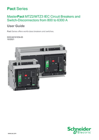
  • 17. Drawout Device MasterPact MTZ2/MTZ3 IEC Circuit Breakers and Switch- Disconnectors from 800 to 6300 A Drawout Device Definition A drawout device is composed of the moving part (also called the device) and the fixed part (or chassis). Drawout Device Moving Part Description The following image shows the standard version of the moving part of a drawout device (no optional accessories). A Carrying grip B Arc chute C Blue fault-trip reset button D Opening pushbutton E Closing pushbutton F Spring charging handle G Terminal block connectors H Front cover I VBP pushbutton locking cover (optional) J Rating plate K Spring charged and ready-to-close indicator L Main-contact position indicator M Window to consult the (optional) CDM mechanical operation counter N Control unit O Control unit transparent cover DOCA0101EN-05 17
  • 18. MasterPact MTZ2/MTZ3 IEC Circuit Breakers and Switch- Disconnectors from 800 to 6300 A Drawout Device Drawout Device Accessories Description The following image shows the accessories available for the moving part of a drawout device. A VDC mismatch protection B Terminal block connectors for optional accessories C Terminal block connectors for standard accessories D Optional block of four OF indication contacts or EF combined connected/closed contacts E Four OF indication contacts (delivered as standard) F KMT grounding kit G MCH gear motor H CDM mechanical operation counter Z1, Z2 See following images 18 DOCA0101EN-05
  • 19. Drawout Device MasterPact MTZ2/MTZ3 IEC Circuit Breakers and Switch- Disconnectors from 800 to 6300 A The following images zoom in on the accessories for the moving part of a drawout device. I Standard SDE1 fault-trip indication contact J Optional SDE2 fault-trip indication contact or RES electrical remote reset K Microswitch L IBPO interlock between racking handle and opening pushbutton M M2C programmable contacts or ESM ERMS switch module N Isolation module O MN undervoltage release or MX2 opening voltage release P MX1 opening voltage release Q PF ready-to-close contact R XF closing voltage release S BPFE electrical closing pushbutton T VCPO OFF-position locking by padlocks U VSPO OFF-position locking by keylocks DOCA0101EN-05 19
  • 20. MasterPact MTZ2/MTZ3 IEC Circuit Breakers and Switch- Disconnectors from 800 to 6300 A Drawout Device Chassis Description The following image shows the standard version of the chassis (no optional accessories). A Carrying grip B ULP port module C Terminal blocks supplied as standard D Terminal block identification plate E Top safety shutter F Bottom safety shutter G Rail release tab H Drawout grip I Extension rail J Racking handle storage space K Racking handle L Moving part position indicator M Racking handle socket N Position release button O Chassis locking by padlocks P Latch for switching chassis locking from disconnected position to any position (connected, test, disconnected) Q Shutter locking block 20 DOCA0101EN-05
  • 21. Drawout Device MasterPact MTZ2/MTZ3 IEC Circuit Breakers and Switch- Disconnectors from 800 to 6300 A Chassis Accessories Description The following image shows the accessories available for the chassis. A VDC mismatch protection B Drawout device position contacts C Optional terminal block D Cord between ULP port module and EIFE interface E EIFE embedded Ethernet interface F Circuit breaker auxiliary terminal shield G VPOC open-door racking interlock H VIVC shutter position indication and locking I IBPO interlock between racking handle and opening pushbutton J VSPD chassis locking by keylocks K VPEC door interlock DOCA0101EN-05 21
  • 22. MasterPact MTZ2/MTZ3 IEC Circuit Breakers and Switch- Disconnectors from 800 to 6300 A Drawout Device Chassis Terminal Block Description Terminal block supplied as standard on the chassis Optional terminal block on the chassis (1) Supplied as standard with chassis for MasterPact MTZ2/MTZ3 circuit breakers only (2) Supplied as standard with 3P chassis only 22 DOCA0101EN-05
  • 23. Drawout Device MasterPact MTZ2/MTZ3 IEC Circuit Breakers and Switch- Disconnectors from 800 to 6300 A Assignment of Terminal Blocks The following table describes the assignment and the availability of the terminal blocks for drawout circuit breakers and switch-disconnectors: • Standard terminal blocks are delivered on the chassis, even if the associated optional accessories are not installed in the device. • Optional terminal blocks are delivered on the chassis only if the associated optional accessories are installed in the device. • N/A indicates that the terminal blocks and the associated optional accessories are not compatible with the device. Block Marking Description Circuit breaker Switch-disconnector A CD1–CD3 CE4–CE6 3 CD disconnected position contacts or 3 CE connected position contacts Optional Optional B COM ULP port module Standard N/A UC1 Zone selective interlocking (ZSI), rectangular sensor for earth-leakage protection, or MDGF module input Standard Standard UC2 Neutral external sensor, rectangular sensor for earth-leakage protection, or MDGF module input Standard Standard SDE2/RES SDE2 additional fault-trip indication contact Optional N/A on MasterPact MTZ NA, HA, HA10 Optional on MasterPact MTZ2 HF, HH or RES electrical remote reset N/A UC4 External voltage connector Optional N/A UC3 External voltage connector Standard on 3P circuit breakers Standard on 3P switch- disconnectors Optional on 4P circuit breakers N/A on 4P switch-disconnectors M2C/ESM M2C programmable contacts or ESM ERMS switch module Optional N/A SDE1 SDE1 fault-trip indication contact Standard Standard CE1–CE3 CT4–CT6 3 CE connected position contacts or 3 CT test position contacts Optional Optional C MN/MX2 MN undervoltage release or MX2 opening voltage release Standard Standard MX1 MX1 opening voltage release Standard Standard XF XF closing voltage release Standard Standard PF PF ready-to-close contact Standard Standard MCH MCH gear motor Standard Standard D(1) OF11–OF24 EF11–EF24 8 OF indication contacts or 8 EF combined connected/closed position auxiliary contacts Optional Optional OF1–OF4 4 OF indication contacts Standard Standard CT1–CT3 CD4–CD6 CE7–CE9 3 CT test position contacts or 3 CD disconnected position contacts or 3 CE connected position contacts Optional Optional DOCA0101EN-05 23
  • 24. MasterPact MTZ2/MTZ3 IEC Circuit Breakers and Switch- Disconnectors from 800 to 6300 A Drawout Device Block Marking Description Circuit breaker Switch-disconnector D(2) OF11–OF22 EF11–EF22 6 OF indication contacts or 6 EF combined connected/closed position auxiliary contacts Optional N/A OF1–OF4 4 OF indication contacts Standard Standard EIFE EIFE embedded Ethernet interface Optional N/A (1) Without EIFE interface (2) With EIFE interface 24 DOCA0101EN-05
  • 25. Device Identification MasterPact MTZ2/MTZ3 IEC Circuit Breakers and Switch- Disconnectors from 800 to 6300 A Device Identification Identification The MasterPact MTZ2/MTZ3 device can be identified in the following ways: • Rating plate on device • QR code located: ◦ On the front face of the control unit of the circuit breaker ◦ On the front face of the switch-disconnector • Identification labels on the device and on the chassis A Product identification label B Product checked label C Accessory voltages label D Rating plate E QR code to access product information DOCA0101EN-05 25
  • 26. MasterPact MTZ2/MTZ3 IEC Circuit Breakers and Switch- Disconnectors from 800 to 6300 A Device Identification Product Identification Label Leg- end Description Explanation A Product code The product code is a line of code representing the complete configuration of a MasterPact circuit breaker or switch- disconnector. It is automatically generated for each MasterPact device after completing the configuration using the Product Selector configuration tool. The product code appears on the invoice and on the delivery documents as well as on the MasterPact device and packaging labels. The product code can be entered in the Product Selector configuration tool, which generates the complete configuration of the MasterPact device. B Schneider Electric internal identification numbers – C Description of device The description of the device, specifies the following characteristics: • Range • Rating • Performance level • Number of poles • Control unit type D Certification logos The logos of the mandatory certifications of the device. E Device serial number The device serial number is coded PPYYWWDXXXX, where: • PP: Plant code • YY: Year of manufacture • WW: Week of manufacture • D: Day of the week of manufacture (Monday = 1) • XXXX: The production number of the product on the day. Ranges from 0001 to 9999 For example, PP162330064 is the sixty fourth device manufactured at plant PP on Wednesday, June 8, 2016. Product Checked Label Leg- end Description Explanation F Device serial number See explanation in preceding table. G Device test date code The device test date code is coded PPYYWWD HH:MM, where: • PP: plant code • YY: year of test • WW: week of test • D: day of the week of test (Monday = 1) • HH:MM: the time of test in hours and minutes 26 DOCA0101EN-05
  • 27. Device Identification MasterPact MTZ2/MTZ3 IEC Circuit Breakers and Switch- Disconnectors from 800 to 6300 A Accessory Voltages Label The accessory voltages label gives the voltage of the accessories which are installed in the device and which need to be connected to a power supply. Rating Plate The rating plate with the device information is located on the front cover of the device. Circuit breaker rating plate Switch-disconnector rating plate A Device size and rated current x 100 A B Ui: rated insulation voltage C Ue: rated operational voltage D Frequency E Type of device: circuit breaker or switch-disconnector, suitable for insulation F Ics: rated service short-circuit breaking capacity G Icw: rated short-time withstand current H Standards I Performance level J Uimp: rated impulse withstand voltage K Icu: rated ultimate short-circuit breaking capacity L Selectivity category as per IEC 60947-2 M Place for sticker with IP address of the optional EIFE interface N Icm: rated short-circuit making capacity O Ith: conventional free air thermal current P Ie: rated operational current Q Information related to switch-disconnectors used as unprotected circuit breakers QR Code When the QR code on the front face of a MasterPact MTZ device is scanned with a smartphone running a QR code reader and connected to the Internet, the Go2SE landing page is displayed, page 33. The landing page displays some information about the device and a list of menus. DOCA0101EN-05 27
  • 28. MasterPact MTZ2/MTZ3 IEC Circuit Breakers and Switch- Disconnectors from 800 to 6300 A MicroLogic X Control Unit: Description MicroLogic X Control Unit: Description Introduction The MicroLogic X control unit includes: • LEDs to monitor the status of the circuit breaker • A local Human Machine Interface comprising a graphic display with colored backlight, contextual buttons, and dedicated buttons • LEDs to monitor the cause of trips and alarms Control Unit Description A Ready LED B Service LED C ERMS LED D Graphic display screen E NFC wireless communication zone F Home button G Three contextual buttons H Escape button ESC I Bluetooth LED J Bluetooth activation button K Test button for ground-fault and earth- leakage protection (MicroLogic 6.0 X and 7.0 X) L Test/Reset button for trip cause LEDs and alarms M Mini USB port under rubber cover N Overload and trip cause LEDs O Cover for internal battery P VPS voltage power supply module (optional) Q VPS LED to indicate that the VPS module is supplying the control unit R QR code to access product information S Control unit identification number T Control unit type U Sensor plug with the rated current of the circuit breaker V Plastic cover 28 DOCA0101EN-05
  • 29. MicroLogic X Control Unit: Description MasterPact MTZ2/MTZ3 IEC Circuit Breakers and Switch- Disconnectors from 800 to 6300 A Status LEDs LED Description Ready The Ready LED blinks slowly when the standard protection functions of the control unit are operational. The service LED alerts the user to the health state of the circuit breaker. • Orange LED: medium severity detected alarm that requires non-urgent maintenance action. • Red LED: high severity detected alarm that requires immediate maintenance action. ERMS The ERMS (Energy Reduction Maintenance Setting) LED has the following statuses: • Blue LED: ERMS engaged • Off LED: ERMS disengaged Display Screen with Contextual Buttons and Dedicated Buttons The local HMI screen and buttons are used to: • Navigate the menu structure. • Display monitored values. • Access and edit configuration settings. NFC Communication Zone The NFC communication zone is used to establish an NFC connection between a smartphone running the EcoStruxure Power Device app and the MicroLogic X control unit. When the connection is established, the circuit breaker operating data is automatically uploaded to the smartphone. Bluetooth Activation Button and LED The Bluetooth activation button is used to establish a Bluetooth low energy connection between a smartphone running the EcoStruxure Power Device app and the MicroLogic X control unit. When the connection is established, the circuit breaker can be monitored and controlled from the smartphone. When the Bluetooth LED is blinking, it indicates that the MicroLogic X control unit is in communication with a Bluetooth device. Test Button The test button is used to test the ground-fault protection for MicroLogic 6.0 X and the earth-leakage protection for MicroLogic 7.0 X. DOCA0101EN-05 29
  • 30. MasterPact MTZ2/MTZ3 IEC Circuit Breakers and Switch- Disconnectors from 800 to 6300 A MicroLogic X Control Unit: Description Overload and Trip Cause LEDs The indications of the four trip cause LEDs depend on the type of MicroLogic X control unit. LEDs Description • MicroLogic 2.0 X, 5.0 X, 6.0 X, 7.0 X: Overload pre-alarm, the load exceeds 90% and is lower than 105% of the Ir setting of the long- time protection. • MicroLogic 2.0 X, 5.0 X, 6.0 X, 7.0 X: Overload alarm, the load exceeds 105% of the Ir setting of the long-time protection. • MicroLogic 2.0 X, 5.0 X, 6.0 X, 7.0 X: Trip due to long-time protection. • MicroLogic 2.0 X: Trip due to instantaneous protection. • MicroLogic 5.0 X, 6.0 X, 7.0 X: Trip due to short-time protection or instantaneous protection. • MicroLogic 2.0 X, 5.0 X: Not applicable. • MicroLogic 6.0 X: Trip due to ground-fault protection. • MicroLogic 7.0 X: Trip due to earth-leakage protection. • MicroLogic 2.0 X, 5.0 X, 6.0 X, 7.0 X: Trip due to optional protections. • MicroLogic 2.0 X, 5.0 X, 6.0 X, 7.0 X: MicroLogic control unit invalid result detected during self test. NOTE: If the MicroLogic X control unit is not powered, the trip cause LEDs go off after 4 hours. After this period, press the Test/Reset button to light them again. Test/Reset Button The Test/Reset button performs the following functions: • Test of the internal battery or check LED functionality: press and hold the Test/Reset button for less than 3 seconds, the four trip cause LEDs switch off for one second. One of the following results: ◦ The four trip cause LEDs switch on for two seconds: the battery is OK. ◦ The four trip cause LEDs flash sequentially for two seconds: the battery is near the end of its life. Replace the battery. ◦ The four trip cause LEDs do not light: replace the battery. NOTE: This test must be carried out immediately after the replacement of the internal battery to check the correct functioning of the new battery. It can then be carried out at any time in the life of the internal battery. • Reset of the latched events: press and hold the Test/Reset button for more than 3 seconds to reset the latched events. The trip cause LEDs and the service LED switch off. 30 DOCA0101EN-05
  • 31. MicroLogic X Control Unit: Description MasterPact MTZ2/MTZ3 IEC Circuit Breakers and Switch- Disconnectors from 800 to 6300 A Mini USB Port Remove the rubber cover of the mini USB port to connect the following devices: • A Mobile Power Pack to supply power to the MicroLogic X control unit. • A smartphone running the EcoStruxure Power Device app through USB OTG connection. • A PC running EcoStruxure Power Commission software. NOTE: The MicroLogic X control unit does not support USB keys. Even if a USB key is connected using an adapter, data is not transferred. QR Code When the QR code on the front face of a MicroLogic X control unit is scanned with a smartphone running a QR code reader and connected to the Internet, the Go2SE landing page is displayed, page 33. The landing page displays some information about the device and a list of menus. Control Unit Identification Number The identification number is made up as follows: • The serial number of the MicroLogic X control unit in the format FFFFFFYYWWDLXXXX • The commercial reference of the control unit in the format LV8••••• Use the identification number to register your MicroLogic X control unit through mySchneider app, the customer care mobile application. Registering your MicroLogic X control unit enables you to keep your records up to date and enables traceability. Control Unit Type This code indicates the type of MicroLogic control unit: • The number (for example, 6.0) defines the types of protection provided by the control unit. • The letter (X) identifies the range of the control unit. Internal Battery The internal battery powers the trip cause LEDs and the main diagnostic functions in the absence of any other power supply. VPS Voltage Power Supply Module The VPS module provides an internal voltage supply to the MicroLogic X control unit. The VPS module is optional for MicroLogic 2.0 X, 5.0 X, and 6.0 X. It is installed as standard on MicroLogic 7.0 X. DOCA0101EN-05 31
  • 32. MasterPact MTZ2/MTZ3 IEC Circuit Breakers and Switch- Disconnectors from 800 to 6300 A MicroLogic X Control Unit: Description Sensor Plug The protection ranges depend on the rated current In, defined by the sensor plug present below the MicroLogic X control unit. 32 DOCA0101EN-05
  • 33. Go2SE Landing Page MasterPact MTZ2/MTZ3 IEC Circuit Breakers and Switch- Disconnectors from 800 to 6300 A Go2SE Landing Page Presentation When the QR code on the front face of a MasterPact MTZ device is scanned with a smartphone running a QR code reader and connected to the Internet, the Go2SE landing page is displayed. The landing page displays information about the device and a list of menus. Landing Page Description The landing page is accessible from Android and iOS smartphones. It displays the same list of menus with slight differences in presentation. The following example shows the landing page displayed on an Android smartphone: A Commercial reference of MicroLogic X control unit B Type of MicroLogic X control unit C Landing page menus. See the following menu descriptions for details. D Downloadable applications Characteristics Selecting this menu gives access to a product datasheet with detailed information about the MicroLogic X control unit. Documentation Selecting this menu gives access to a sub-menu with the following options: • Asset Life Cycle Documents: gives access to Safe Repository. Safe Repository is a web service allowing documentation linked to assets to be consulted, stored, and shared in a Schneider Electric environment. Access to Safe Repository is restricted to authorized users. Safe Repository gives access to the bill of materials of the MasterPact MTZ circuit breaker. • Technical Guidance at Glance: gives access to the MasterPact MTZ technical publications, including: ◦ MasterPact MTZ - MicroLogic X Control Unit - User Guide ◦ MasterPact MTZ1 - Circuit Breakers and Switch-Disconnectors - User Guide DOCA0101EN-05 33
  • 34. MasterPact MTZ2/MTZ3 IEC Circuit Breakers and Switch- Disconnectors from 800 to 6300 A Go2SE Landing Page ◦ MasterPact MTZ2/MTZ3 - Circuit Breakers and Switch-Disconnectors - User Guide ◦ All the instruction sheets for MasterPact MTZ devices and MicroLogic X control units • Product Documentation: gives access to the MicroLogic X technical publications EcoStruxure Facility Expert App Selecting this application gives access to the EcoStruxure Facility Expert mobile application that can be downloaded on Android and iOS smartphones. For smartphone compatibility, check on your application store. EcoStruxure Facility Expert optimizes operations and maintenance, helping to ensure business continuity, and provides insights to service providers or facility managers. EcoStruxure Facility Expert is a real-time collaborative technology available on mobile devices and PCs that enables managers and maintenance personnel to be connected with facilities and equipment. Information exchange between users is simple and fast. The QR code on MasterPact MTZ devices enables managers and maintenance personnel to access the following automatic downloads: • MasterPact MTZ device identifier. • Technical documentation. • The maintenance plan for the MasterPact MTZ device. EcoStruxure Facility Expert enables managers and maintenance personnel to access the maintenance plan for MasterPact MTZ devices. EcoStruxure Facility Expert helps maintenance personnel to diagnose issues remotely and manage maintenance efficiently by: • Providing relevant information on critical assets. • Sending immediate state of the equipment and detailed information helping for diagnostics. EcoStruxure Power Device App Selecting this application gives access to the EcoStruxure Power Device app that can be downloaded and installed on Android and iOS smartphones. For smartphone compatibility, check on your application store. mySchneider App Selecting this application gives access to the Schneider Electric customer care mobile application mySchneider app that can be downloaded on Android and iOS smartphones. For smartphone compatibility, check on your application store. The customer care application offers self-service instructions and easy access to expert support and information. 34 DOCA0101EN-05
  • 35. Operating Conditions MasterPact MTZ2/MTZ3 IEC Circuit Breakers and Switch- Disconnectors from 800 to 6300 A Operating Conditions Introduction MasterPact MTZ devices are designed and tested for operation in industrial atmospheres. It is recommended that equipment is cooled or heated to the proper operating temperature and kept free of excessive vibration and dust. Ambient Temperature MasterPact MTZ devices can operate under the following temperature conditions: • Electrical and mechanical characteristics specified for an ambient temperature of -25 °C to +70 °C. • Circuit-breaker closing specified down to -35 °C by manual operation with closing pushbutton. Storage conditions are as follows: • -40 °C to +85 °C for the device without the control unit. • -25 °C to +85 °C for the control unit. Extreme Atmospheric Conditions MasterPact MTZ devices have successfully passed tests for extreme atmospheric conditions, defined by the following standards: Standard Title IEC 60068-2-1 Dry cold, at -40 °C IEC 60068-2-2 Dry heat, at +85 °C IEC 60068-2-30 Damp heat (temperature +55 °C, relative humidity 95%) IEC 60068-2-52 level 2 Salt mist Industrial Environments MasterPact MTZ devices can operate in the industrial environments defined by IEC 60947 (pollution degree up to 3). It is advisable to check that devices are installed in suitably cooled switchboards without excessive dust. Conditions Standard Corrosive industrial atmospheres Category 3C3 compliant with IEC 60721-3-3 Sea salts 0.8 to 8 mg/m² day average over the year Compliant with IEC 60721-2-5 Mechanically active substances Category 3S3 compliant with IEC 60721-3-3 Beyond these conditions, MasterPact MTZ devices must be installed inside switchboards with an IP rating equal to or greater than IP54. DOCA0101EN-05 35
  • 36. MasterPact MTZ2/MTZ3 IEC Circuit Breakers and Switch- Disconnectors from 800 to 6300 A Operating Conditions Vibration MasterPact MTZ devices have successfully passed tests for the following vibration levels, in compliance with IEC 60068-2-6 and IEC 60068-2-27: • 2 Hz to 13.2 Hz: amplitude +/- 1 mm. • 13.2 Hz to 100 Hz: constant acceleration of 0.7 g. Vibration testing to these levels is required by merchant marine inspection organizations (for example, Veritas, Lloyd’s). MasterPact MTZ devices have also been successfully tested according to: • Annex Q - IEC 60947-1: Special tests – damp heat, salt mist, vibration and shock • IEC 60947-1 - Category D: Environment subject to temperature, humidity and vibration Altitude MasterPact MTZ devices are designed and tested to operate at altitudes below 2,000 m. At altitudes above 2,000 m, the characteristics of the ambient air (electrical resistance, cooling capacity) lower product characteristics as follows: Characteristics Altitude 2,000 m 3,000 m 4,000 m 5,000 m Impulse withstand voltage Uimp (kV) 12 11 10 8 Rated insulation voltage (Ui) (V) 1,000 900 780 700 Maximum rated operational voltage 50/ 60 Hz Ue (V) MasterPact MTZ2/ MTZ3 except H10 690 690 630 560 MasterPact MTZ2/ MTZ3 H10 1,000 890 795 700 Rated current (A) at 40 °C 1 x In 0.99 x In 0.96 x In 0.94 x In NOTE: Intermediate values can be obtained by interpolation. Electromagnetic Disturbances MasterPact MTZ devices have protection against: • Overvoltages caused by devices that generate electromagnetic disturbance. • Overvoltages caused by atmospheric disturbance or by a distribution-system outage (for example, a lighting system failure). • Devices emitting radio waves (for example, radio transmitters, walkie-talkies, or radar). • Electrostatic discharge produced by users. MasterPact MTZ devices have successfully passed the electromagnetic- compatibility tests (EMC) defined by the following international standards: • IEC 60947-2, appendix F. • IEC 60947-2, appendix B (control units with earth-leakage function). The devices have passed the above tests and therefore: • No nuisance tripping occurs. • Tripping times are respected. 36 DOCA0101EN-05
  • 37. MasterPact MTZ2/MTZ3 IEC Circuit Breakers and Switch- Disconnectors from 800 to 6300 A MasterPact MTZ2/MTZ3 Normal Operation What’s in This Part Device Operating Actions................................................................................38 Drawout Device Racking Actions.....................................................................65 Device Locking Actions...................................................................................83 Device Interlocking Actions ...........................................................................100 DOCA0101EN-05 37
  • 38. MasterPact MTZ2/MTZ3 IEC Circuit Breakers and Switch- Disconnectors from 800 to 6300 A Device Operating Actions Device Operating Actions What’s in This Chapter Operating the Device.....................................................................................39 Control Modes ..............................................................................................43 Opening the Device.......................................................................................49 Closing the Device ........................................................................................51 Resetting the Circuit Breaker..........................................................................55 Engaging the ERMS Function ........................................................................56 Operating Accessories...................................................................................58 38 DOCA0101EN-05
  • 39. Device Operating Actions MasterPact MTZ2/MTZ3 IEC Circuit Breakers and Switch- Disconnectors from 800 to 6300 A Operating the Device Device Status The indicators on the front of the device show the following information: • Reset button: ◦ In: the device is closed or open voluntarily (not tripped) ◦ Out: the device has tripped • Position indicator of main contacts: ON or OFF. • Closing spring and ready-to-close indicator. The state can be one of the following: ◦ Discharged (no energy to close the circuit breaker) ◦ Charged not ready-to-close ◦ Charged ready-to-close A Reset button B Position indicator of main contacts C Closing spring and ready-to-close indicator The combination of both indicators gives the device status: Position indicator of main contacts Closing spring and ready-to- close indicator Device status description Device is off (main contacts are open) and closing spring is discharged. Device is off (main contacts are open) and closing spring is charged. The device is not ready-to-close because at least one of the following conditions is true: • The device has tripped and must be reset. • The MX opening voltage release is energized. • The MN undervoltage release is not energized. • The device is mechanically locked in the open position by using padlock or keylock or by using an interlocking system. Device is off (main contacts are open) and closing spring is charged. The device is ready-to-close. Device is on (main contacts are closed) and closing spring is discharged. Device is on (main contacts are closed) and closing spring is charged. The device is not ready-to-close because it is already closed. DOCA0101EN-05 39
  • 40. MasterPact MTZ2/MTZ3 IEC Circuit Breakers and Switch- Disconnectors from 800 to 6300 A Device Operating Actions Device Indication Contacts The position of the device main contacts is indicated by OF indication contacts. Name Contact number Position of indicators and contacts Device status – ON OFF Tripped (by MicroLogic X control unit) Position indicator of main contacts – Main contact position – Closed Open Open Reset button position – IN IN OUT OF indication contact position 1–2 Open Closed Closed 1–4 Closed Open Open SDE indication contact position 1–2 Closed Closed Open 1–4 Open Open Closed Anti-Pumping Function MasterPact MTZ devices provide a mechanical anti-pumping function. In the event of simultaneous maintained opening and closing orders, the standard mechanism blocks the main contacts in the open position. After a trip due to an electrical fault or intentional opening using the manual or electrical controls, the closing order must first be discontinued, then reactivated to close the circuit breaker. This prevents a cycle of closing and opening. When remote operation features are used, allow at least four seconds for the MCH gear motor to charge the device closing spring completely before the XF closing voltage release is actuated. To prevent the device from closing prematurely, the PF ready-to-close contact can be series connected with the XF closing voltage release. Charging the Closing Spring The closing spring must be charged with sufficient energy to close the MasterPact MTZ: • Manual charge: Charge the mechanism by pulling the spring charging handle down seven times. • Automatic charge: If the optional MCH gear motor is installed, the spring is automatically charged after closing. 40 DOCA0101EN-05
  • 41. Device Operating Actions MasterPact MTZ2/MTZ3 IEC Circuit Breakers and Switch- Disconnectors from 800 to 6300 A Manual Operation Cycle with the Spring Charging Handle The following image shows an Open/Close/Open (OCO) cycle for manually charged devices without MCH gear motor: DOCA0101EN-05 41
  • 42. MasterPact MTZ2/MTZ3 IEC Circuit Breakers and Switch- Disconnectors from 800 to 6300 A Device Operating Actions Electrical Operation Cycle with an MCH Gear Motor The following image shows an Open/Close/Open (OCO) cycle for electrically charged devices using an MCH gear motor: 42 DOCA0101EN-05
  • 43. Device Operating Actions MasterPact MTZ2/MTZ3 IEC Circuit Breakers and Switch- Disconnectors from 800 to 6300 A Control Modes Presentation The circuit breaker control mode is a MicroLogic X setting which defines the means to control the opening and closing functions of the circuit breaker. Two control modes are available: Manual and Auto. Manual control mode only accepts orders made using one of the following: • The mechanical buttons on the front of the circuit breaker. • The external pushbutton connected to the MN/MX/XF voltage releases. • The BPFE electrical closing pushbutton. Auto control mode has two settings: Local or Remote. All orders accepted in Manual control mode are accepted in Auto control mode, as well as orders from local or remote communication as follows: • Auto Local: the operator needs to be close to the circuit breaker to establish communication and only orders sent from a local source through communication are accepted: ◦ EcoStruxure Power Commission software through USB connection ◦ EcoStruxure Power Device app with MasterPact Operation Assistant Digital Module through Bluetooth or USB OTG connection • Auto Remote: the operator does not need to be next to the circuit breaker to establish communication and orders are accepted only when sent from a remote source through the communication network. NOTE: EcoStruxure Power Commission software connected through the communication network can be used to send control orders to the circuit breaker. The control mode factory setting is Auto Remote. NOTE: The switch-disconnector control mode corresponds to the Manual control mode of circuit breakers. To operate a switch-disconnector through communication, it is possible to use an IO module. Refer to DOCA0055EN Enerlin'X IO – Input/Output Application Module for One IEC Circuit Breaker – User Guide. Operation According to Control Mode Configured The following table summarizes the opening and closing operations available, depending on the control mode configured: Control mode Type of order and delivery method Mechani- cal Electrical Through communication Pushbut- ton BPFE Point to point (voltage release) IO module FDM121 display EcoStrux- ure Power Commis- sion software (1) EcoStruxure Power Device app + MasterPact Operation Assistant Digital Module(2) Commu- nication network FDM128 display IFE/EIFE Weblogs Manual ✔ ✔ ✔ – – – – – – – Auto: Local ✔ ✔ ✔ ✔(3) ✔ ✔ ✔ – – – Auto: Remote ✔ ✔ ✔ ✔(3) – – – ✔ ✔ ✔ (1) Through USB (2) Through Bluetooth or USB OTG (3) According to IO input mode setting DOCA0101EN-05 43
  • 44. MasterPact MTZ2/MTZ3 IEC Circuit Breakers and Switch- Disconnectors from 800 to 6300 A Device Operating Actions Operation in Manual Control Mode FDM128 FDM121 1 2 3 4 13 IO EcoStruxure Power Commission SCADA IFE/EIFE webpages EcoStruxure Power Device app EcoStruxure Power Commission Ethernet ETH2 Reset R 0 I EIFE XF MX MN ULP BPFE D A B FDM121 EcoStruxure Power Commission SCADA IFE/EIFE webpages FDM128 13 1 2 2 3 3 4 IO EcoStruxure Power Device app EcoStruxure Power Commission ~/= C A MicroLogic X control unit B ULP port module C EIFE embedded Ethernet interface D Circuit breaker mechanism Opening and closing operations available in Manual control mode: • 0: mechanical opening pushbutton • 1: mechanical closing pushbutton • BPFE: electrical closing pushbutton • External pushbuttons wired by customer, and connected to: ◦ XF: standard or communicating and diagnostic closing voltage release ◦ MX: standard or communicating and diagnostic opening voltage release ◦ MN: standard or diagnostic undervoltage release 44 DOCA0101EN-05
  • 45. Device Operating Actions MasterPact MTZ2/MTZ3 IEC Circuit Breakers and Switch- Disconnectors from 800 to 6300 A Operation in Auto: Local Mode FDM128 FDM121 2 3 13 O1 O2 O3 A1 I1 I2 I3 I4 I5 I6 C C C 14 23 24 33 34 T1 T2 2 2 3 3 T 24VDC EcoStruxure Power Commission SCADA IFE/EIFE webpages EcoStruxure Power Device app Ethernet ~/= ETH1 ETH2 Reset R 0 I EIFE XF MX MN ULP BPFE C IO D A B ETH1 EcoStruxure Power Commission SCADA IFE/EIFE webpages E EcoStruxure Power Commission A MicroLogic X control unit B ULP port module C EIFE embedded Ethernet interface D Circuit breaker mechanism E IO input/output application module Opening and closing operations available in Auto: Local mode: • 0: mechanical opening pushbutton • 1: mechanical closing pushbutton • BPFE: electrical closing pushbutton • External pushbuttons wired by customer, and connected to: ◦ XF: communicating and diagnostic closing voltage release ◦ MX: communicating and diagnostic opening voltage release ◦ MN: standard or diagnostic undervoltage release • IO: with the Breaker Operation predefined application of the IO module set to local control mode • EcoStruxure Power Commission software: command sent through USB connection • EcoStruxure Power Device app with MasterPact Operation Assistant Digital Module: ◦ Through Bluetooth low energy wireless communication ◦ Through USB OTG connection DOCA0101EN-05 45
  • 46. MasterPact MTZ2/MTZ3 IEC Circuit Breakers and Switch- Disconnectors from 800 to 6300 A Device Operating Actions Operation in Auto: Remote Mode 13 O1 O2 O3 A1 I1 I2 I3 I4 I5 I6 C C C 14 23 24 33 34 T1 T2 AI O1 O2 O3 LV434063 AI O1 O2 O3 LV434063 T 24VDC EcoStruxure Power Commission SCADA IFE/EIFE webpages EcoStruxure Power Device app EcoStruxure Power Commission EcoStruxure Power Device app EcoStruxure Power Commission Ethernet E ~/= ETH1 ETH2 Reset R 0 I EIFE XF MX MN ULP BPFE C IO D A B FDM128 FDM128 FDM121 A MicroLogic X control unit B ULP port module C EIFE embedded Ethernet interface D Circuit breaker mechanism E IO input/output application module Opening and closing operations available in Auto: Remote mode: • 0: mechanical opening pushbutton • 1: mechanical closing pushbutton • BPFE: electrical closing pushbutton • External pushbuttons wired by customer, and connected to: ◦ XF: communicating and diagnostic closing voltage release ◦ MX: communicating and diagnostic opening voltage release ◦ MN: standard or diagnostic undervoltage release • IO: with the Breaker Operation predefined application of the IO module set to remote control mode • Communication: remote command through IFE, EIFE, or IFM interface. 46 DOCA0101EN-05
  • 47. Device Operating Actions MasterPact MTZ2/MTZ3 IEC Circuit Breakers and Switch- Disconnectors from 800 to 6300 A Setting the Control Mode The Auto or Manual control mode can be set as follows: • On the MicroLogic X display screen, at Home > Configuration > Communication > Control Mode > Mode. • With the EcoStruxure Power Device app through Bluetooth or USB OTG connection. The Local or Remote mode can be set as follows: • When the IO module is used with the Breaker Operation predefined application, the local or remote mode is defined only by the control mode selector switch wired on the digital input I1 of the IO module. • When the IO module is not used with the Breaker Operation predefined application, the local or remote mode can be set as follows: ◦ With EcoStruxure Power Commission software through USB connection. ◦ With the EcoStruxure Power Device app through Bluetooth or USB OTG connection. ◦ With the FDM121 display connected to the MicroLogic X control unit through the ULP system. NOTE: • The Local or Remote mode cannot be set on the MicroLogic X display screen. • When Auto control mode is set, the control mode is Auto Local or Auto Remote, depending on the last setting. Displaying the Control Mode The control mode (Manual, Auto Local, or Auto Remote) is displayed as follows: • On the MicroLogic X display screen, at Home > Configuration > Communication > Control Mode > Mode • With EcoStruxure Power Commission software through USB connection • With the EcoStruxure Power Device app through Bluetooth or USB OTG connection • On the IFE/EIFE webpages • By a remote controller using the communication network. Predefined Events Changing the control mode settings generates the following events: Code Event History Severity 0x1002 (4098) Manual mode enabled Operation Low 0x1004 (4100) Local mode enabled Operation Low 0x0D0D (3341) Config. error IO and CU - Local/Remote mode Configuration Medium Recommended Actions Code Event Recommended actions 0x0D0D (3341) Config. error IO and CU - Local/Remote mode Correct the configuration error with EcoStruxure Power Commission: • If you want the L/R mode to be controlled by the IO module, connect an IO module with L/R mode assignment. • If you do not want the L/R mode to be controlled by the IO module, connect an IO module without L/R mode assignment. DOCA0101EN-05 47
  • 48. MasterPact MTZ2/MTZ3 IEC Circuit Breakers and Switch- Disconnectors from 800 to 6300 A Device Operating Actions 48 DOCA0101EN-05
  • 49. Device Operating Actions MasterPact MTZ2/MTZ3 IEC Circuit Breakers and Switch- Disconnectors from 800 to 6300 A Opening the Device Opening Conditions To open the device, the device must be closed (I). NOTE: An opening order always takes priority over a closing order. Opening the Device The following tables present the different ways to open the device in the different control modes available. The device can be opened in the following ways in all control modes: Opening type Control mode Accessories Opening action Mechanical Manual, Auto: Local, or Auto: Remote – Press the opening pushbutton on the front of the device. This opening action is possible at any time. Automatic Manual, Auto: Local, or Auto: Remote MN undervoltage release, with or without MN delay unit The MN undervoltage release opens the device automatically in the case of voltage drop. By external pushbutton Manual, Auto: Local, or Auto: Remote • External pushbutton wired by customer • One of the following accessories: ◦ MX standard or communicating opening voltage release ◦ MN undervoltage release, with or without MN delay unit Press the external pushbutton which is connected to the MX opening voltage release or to the MN undervoltage release via the customer terminal block. When the MN undervoltage release is connected to the MN delay unit, the device opens with the corresponding time delay. DOCA0101EN-05 49
  • 50. MasterPact MTZ2/MTZ3 IEC Circuit Breakers and Switch- Disconnectors from 800 to 6300 A Device Operating Actions In addition, the circuit breaker can be opened in the following ways when Auto control mode is configured. DANGER HAZARD OF ELECTRIC SHOCK, EXPLOSION, OR ARC FLASH • Do not operate the circuit breaker without confirming that doing so will not create a hazardous situation. • Do not allow any person to work on the electrical network without physically validating the successful execution of the local or remote software actions for opening the circuit breaker or switching off the electrical circuit. Failure to follow these instructions will result in death or serious injury. Opening type Control mode Accessories Opening action Through IO module Auto: Local or Auto: Remote • MX communicating opening voltage release • Isolation module • ULP port module • IO module Open the circuit breaker by using the predefined application 2 Breaker Operation of the IO module. • When the circuit breaker is set to local control mode by the IO module, the command to open is issued from local pushbuttons wired on digital inputs. • When the circuit breaker is set to remote control mode by the IO module, the command to open is issued from remote PLC outputs wired on digital inputs. Refer to DOCA0055EN Enerlin'X IO – Input/Output Application Module for One IEC Circuit Breaker – User Guide. Through FDM121 display Auto: Local • MX communicating opening voltage release • Isolation module • ULP port module • IO module Send a command to open the circuit breaker from FDM121 display connected locally to the circuit breaker through the ULP system. The opening action is password-protected. Through EcoStruxure Power Commission software Auto: Local • MX communicating opening voltage release • Isolation module Send a command to open the circuit breaker from EcoStruxure Power Commission software running on a PC connected locally to the device through the mini USB port on the MicroLogic X control unit. This opening action is password-protected. Refer to EcoStruxure Power Commission Online Help. Through EcoStruxure Power Device app Auto: Local • MX communicating opening voltage release • Isolation module • MasterPact Operation Assistant Digital Module Send a command to open the circuit breaker from the EcoStruxure Power Device app with MasterPact Operation Assistant Digital Module, through Bluetooth wireless communication or USB OTG connection. The opening action is password-protected. Through Modbus communication Auto: Remote • MX communicating opening voltage release • Isolation module • ULP port module • IFE, EIFE, or IFM interface, or IFE server Send a command to open the circuit breaker through the Modbus communication network. This opening action is password-protected. Refer to DOCA0105EN MasterPact MTZ – Modbus Communication – User Guide. NOTE: EcoStruxure Power Commission software running on a PC connected to the device through the communication network can be used to send commands to open. 50 DOCA0101EN-05
  • 51. Device Operating Actions MasterPact MTZ2/MTZ3 IEC Circuit Breakers and Switch- Disconnectors from 800 to 6300 A Opening type Control mode Accessories Opening action Through IEC 61850 communication Auto: Remote • MX communicating opening voltage release • Isolation module • ULP port module • IFE or EIFE interface • IEC 61850 for MasterPact MTZ Digital Module Send a command to open the circuit breaker through the IEC 61850 communication network. This opening action is password-protected. Refer to DOCA0162EN MasterPact MTZ - IEC 61850 Communication Guide. Through IFE/EIFE webpages Auto: Remote • MX communicating opening voltage release • Isolation module • ULP port module • IFE or EIFE interface, or IFE server Send a command to open the circuit breaker from the IFE/EIFE control webpage. This opening action is password-protected. Refer to the relevant document: • DOCA0084EN Enerlin'X IFE – Ethernet Switchboard Server – User Guide • DOCA0142EN Enerlin'X IFE - Ethernet Interface for One IEC Circuit Breaker - User Guide • DOCA0106EN Enerlin'X EIFE – Embedded Ethernet Interface for One MasterPact MTZ Drawout Circuit Breaker – User Guide If the device does not open, refer to Troubleshooting, page 150. Closing the Device Closing Conditions To close the device, the following conditions must be met: • Device is open (O). • Closing spring is charged. • The device is ready to close, OK is displayed. NOTE: An opening order always takes priority over a closing order. The device cannot be closed while an opening order is being received. If OK is crossed-out on the ready-to-close indicator, an order to open is being received (either electrically or mechanically) and must be ended before OK can be displayed. DANGER HAZARD OF ELECTRIC SHOCK, EXPLOSION, OR ARC FLASH Do not re-close the device on an electrical fault. First inspect and, if necessary, repair the downstream equipment. Failure to follow these instructions will result in death or serious injury. Closing the Device The following tables present the different ways to close the device in the different control modes available. The device can be closed in the following ways in all control modes: DOCA0101EN-05 51
  • 52. MasterPact MTZ2/MTZ3 IEC Circuit Breakers and Switch- Disconnectors from 800 to 6300 A Device Operating Actions Closing type Control mode Accessories Closing action Mechanical Manual, Auto: Local, or Auto: Remote – Press the closing pushbutton on the front of the device. The closing action is possible when the closing conditions are met. Electrical with BPFE Manual, Auto: Local, or Auto: Remote • BPFE electrical closing pushbutton • XF communicating closing voltage release • Isolation module Press the BPFE electrical closing pushbutton, mounted on the front cover. The closing action takes into account internal closing conditions of the device and the external conditions that are part of the control and monitoring system of the installation. External pushbutton Manual, Auto: Local, or Auto: Remote • External pushbutton wired by customer • XF standard or communicating closing voltage release • Isolation module • MCH gear motor Press the external pushbutton, which is connected to the XF closing voltage release through the customer terminal block. In addition, the circuit breaker can be closed in the following ways when Auto control mode is configured. DANGER HAZARD OF ELECTRIC SHOCK, EXPLOSION, OR ARC FLASH • Do not operate the circuit breaker without confirming that doing so will not create a hazardous situation. • Do not allow any person to work on the electrical network without physically validating the successful execution of the local or remote software actions for closing the circuit breaker or switching on the electrical circuit. Failure to follow these instructions will result in death or serious injury. Closing type Control mode Accessories Closing action Through IO module Auto: Local or Auto: Remote • XF communicating closing voltage release • Isolation module • MCH gear motor • ULP port module • IO module Close the circuit breaker by using the predefined application 2 Breaker Operation of the IO module: • When the circuit breaker is set to local control mode by the IO module, the command to close is issued from local pushbuttons wired on digital inputs. • When the circuit breaker is set to remote control mode by the IO module, the command to close is issued from remote PLC outputs wired on digital inputs. Refer to DOCA0055EN Enerlin'X IO - Input/Output Application Module for One IEC Circuit Breaker - User Guide. Through FDM121 display Auto: Local • XF communicating closing voltage release • Isolation module • MCH gear motor • ULP port module • IO module Send a command to close the circuit breaker from FDM121 display connected locally to the circuit breaker through the ULP system. The closing action is password-protected. Through EcoStruxure Power Commission software Auto: Local • XF communicating closing voltage release • Isolation module Send a command to close the circuit breaker from EcoStruxure Power Commission software running on a PC connected locally to the circuit breaker through the mini USB port on the MicroLogic X control unit. 52 DOCA0101EN-05
  • 53. Device Operating Actions MasterPact MTZ2/MTZ3 IEC Circuit Breakers and Switch- Disconnectors from 800 to 6300 A Closing type Control mode Accessories Closing action • MCH gear motor The closing action is password-protected. Refer to EcoStruxure Power Commission Online Help. Through EcoStruxure Power Device app Auto: Local • XF communicating closing voltage release • Isolation module • MCH gear motor • MasterPact Operation Assistant Digital Module Send a command to close the circuit breaker from the EcoStruxure Power Device app with MasterPact Operation Assistant Digital Module, through Bluetooth wireless communication or USB OTG connection. The closing action is password-protected. Through Modbus communication Auto: Remote • XF communicating closing voltage release • Isolation module • MCH gear motor • ULP port module • IFE, EIFE, or IFM interface, or IFE server Send a command to close the circuit breaker through the Modbus communication network. The closing action is password-protected. Refer to DOCA0105EN MasterPact MTZ - Modbus Communication Guide. NOTE: EcoStruxure Power Commission software running on a PC connected to the circuit breaker through the communication network can be used to send commands to close. Through IEC 61850 communication Auto: Remote • XF communicating closing voltage release • Isolation module • MCH gear motor • ULP port module • IFE or EIFE interface • IEC 61850 for MasterPact MTZ Digital Module Send a command to close the circuit breaker through the IEC 61850 communication network. This closing action is password-protected. Refer to DOCA0162EN MasterPact MTZ - IEC 61850 Communication Guide. Through IFE/EIFE webpages Auto: Remote • XF communicating closing voltage release • Isolation module • MCH gear motor • ULP port module • IFE or EIFE interface, or IFE server Send a command to close the circuit breaker from the IFE/EIFE control webpage. The closing action is password-protected. Refer to the relevant document: • DOCA0084EN Enerlin'X IFE – Ethernet Switchboard Server – User Guide • DOCA0142EN Enerlin'X IFE - Ethernet Interface for One IEC Circuit Breaker - User Guide • DOCA0106EN Enerlin'X EIFE – Embedded Ethernet Interface for One MasterPact MTZ Drawout Circuit Breaker – User Guide If the device does not close, refer to Troubleshooting, page 150. Inhibiting the Closing Function The closing function can be inhibited by sending a command through: • The communication network or EcoStruxure Power Commission software • The IO module NOTE: Using EcoStruxure Power Commission software, you can determine whether the closing inhibition can be controlled using the IO module. For more information, refer to EcoStruxure Power Commission Online Help. WARNING RESTRICTED CLOSING INHIBITION Do not use the inhibit closing order to lock the circuit breaker in open position. Failure to follow these instructions can result in death, serious injury, or equipment damage. DOCA0101EN-05 53
  • 54. MasterPact MTZ2/MTZ3 IEC Circuit Breakers and Switch- Disconnectors from 800 to 6300 A Device Operating Actions The inhibit close order inhibits only the closing orders allowed in Auto control mode. The closing orders issued from the mechanical closing pushbutton or BPFE, or from the pushbutton directly connected to the XF voltage release are not inhibited. 54 DOCA0101EN-05
  • 55. Device Operating Actions MasterPact MTZ2/MTZ3 IEC Circuit Breakers and Switch- Disconnectors from 800 to 6300 A Resetting the Circuit Breaker Resetting Conditions After a trip, the circuit breaker must be reset before closing it. Resetting is possible in all control modes. Resetting the Circuit Breaker The circuit breaker can be reset in different ways, according to the circuit breaker configuration and its accessories: Type of resetting Accessories Resetting action Mechanical with the blue fault-trip reset button – Push in the blue fault-trip reset button on the front of the circuit breaker. This resetting action is always possible. Pushing in the blue fault-trip reset button resets the SDE fault-trip indication contact, and allows the circuit breaker to be closed. Automatic (RAR automatic reset option) • XF communicating or standard closing voltage release • Isolation module • MCH gear motor After a trip, RAR automatic reset allows the circuit breaker to be closed without the blue fault-trip reset button being pushed in. The use of XF closing voltage release is compulsory with this option. The mechanical indicator and the SDE fault-trip indication contact remain in detected fault position. To reset the SDE fault-trip indication contact and the mechanical indicator, push in the blue fault-trip reset button. Electrical with external pushbutton • External pushbutton wired by customer • RES electrical remote reset • XF communicating or standard closing voltage release • Isolation module • MCH gear motor Press the external pushbutton which is connected to the RES electrical remote reset via the customer terminal block. The use of XF closing voltage release is compulsory with this option. The RES electrical remote reset resets the SDE fault-trip indication contact and the mechanical indicator, and allows the circuit breaker to be closed. NOTE: The RES electrical remote reset is not compatible with the SDE2 option. DOCA0101EN-05 55
  • 56. MasterPact MTZ2/MTZ3 IEC Circuit Breakers and Switch- Disconnectors from 800 to 6300 A Device Operating Actions Engaging the ERMS Function Presentation Engage the ERMS function to reduce protection settings so that the circuit breaker trips as soon as possible when an internal arc fault occurs. Minimizing the time between fault and trip helps to reduce the risk of injury when qualified electrical personnel are near energized equipment. Conditions for Engaging the ERMS Function The ERMS function is available when the Energy Reduction Maintenance Settings Digital Module is purchased and installed on the MicroLogic X control unit. Operating Principle The ERMS function can be engaged as follows: • With the EcoStruxure Power Device app (password-protected). There is a digital lock between a smartphone running the EcoStruxure Power Device app and the MicroLogic X control unit. • By using an external selector switch connected to the optional ESM ERMS switch module. The ESM module is installed in the circuit breaker and is connected to an external selector switch, which can be padlocked. The ERMS function is engaged by turning the external selector switch. The ERMS function can be engaged with both the EcoStruxure Power Device app (password-protected) and an external selector switch. The ERMS function must be disengaged by the interface that engaged it: • If it is engaged on a smartphone, it must be disengaged by the same smartphone. • If it is engaged by the external ERMS switch connected to the ESM module, it must be disengaged by the ERMS switch. • If it is engaged by both smartphone and ERMS switch, it must be disengaged by both smartphone and ERMS switch. While the ERMS function is engaged: • A blue ERMS LED (A) is lit on the front face of the MicroLogic X control unit • Quick View scrolling is interrupted and the ERMS engaged message is displayed with a blue backlight • All screens, except pop-up messages, are displayed with a blue backlight For more information, refer to DOCA0102EN MasterPact MTZ – MicroLogic X Control Unit – User Guide. 56 DOCA0101EN-05
  • 57. Device Operating Actions MasterPact MTZ2/MTZ3 IEC Circuit Breakers and Switch- Disconnectors from 800 to 6300 A Engaging the ERMS Function NOTICE HAZARD OF LOSS OF POWER Ensure that the ERMS protection settings are properly configured prior to engagement. Failure to follow these instructions can result in loss of service due to power loss. The ERMS can be engaged in different ways, according to the circuit breaker configuration and its accessories: Type Accessories Action Through EcoStruxure Power Device app – Send a command from the EcoStruxure Power Device app to engage the ERMS function, through Bluetooth wireless communication or USB OTG connection. The action is password-protected. Through an external selector switch connected to the ESM module • ESM ERMS switch module • External selector switch Turn the external selector switch to the Engaged position Disengaging the ERMS Function DANGER HAZARD OF ELECTRIC SHOCK, EXPLOSION, OR ARC FLASH Prior to disengaging ERMS: • Carefully inspect your work area, and remove any tools and objects left inside the equipment. • Ensure that all personnel are away from the equipment, and devices, doors, and covers are in place. Failure to follow these instructions will result in death or serious injury. A digital lock function establishes a digital lock between a smartphone running the EcoStruxure Power Device app and the MicroLogic X control unit when ERMS is engaged by the smartphone. The digital lock function ensures that when the ERMS function is engaged by a smartphone, it must be disengaged by the same smartphone. The way to disengage the ERMS function depends on how it was engaged: Type Accessories Action Through EcoStruxure Power Device app – Disengage the ERMS function on the same smartphone that engaged it Through an external selector switch • ESM ERMS switch module • External selector switch Turn the external selector switch to the Disengaged position Through EcoStruxure Power Device app and an external selector switch • ESM ERMS switch module • External selector switch • Disengage the ERMS function on the same smartphone that engaged it • Turn the external selector switch to the Disengaged position DOCA0101EN-05 57
  • 58. MasterPact MTZ2/MTZ3 IEC Circuit Breakers and Switch- Disconnectors from 800 to 6300 A Device Operating Actions Operating Accessories XF, MX, and MN Voltage Releases XF, MX, and MN voltage releases are optional accessories mounted inside the device. They can be of standard type or diagnostic and communicating type (standard or with diagnostic function for MN undervoltage release). The standard voltage releases are designed to receive either pulse-type or maintained voltage operating orders. XF Closing Voltage Release (Standard or With Diagnostic and Communicating Function) The XF closing voltage release closes the circuit breaker instantaneously when powered if the spring mechanism is charged. The minimum duration of the pulse operating order must be 200 ms. For information on installation, consult the instruction sheet on the Schneider Electric website: • XF standard closing voltage release: NVE40749 • XF communicating closing voltage release: NVE40766 MX Opening Voltage Release (Standard or With Diagnostic and Communicating Function) The MX opening voltage release opens the circuit breaker instantaneously when powered. The minimum duration of the pulse operating order must be 200 ms. The MX standard opening voltage release locks the circuit breaker in OFF position if the command is maintained. For information on installation, consult the instruction sheet on the Schneider Electric website: • MX standard opening voltage release: NVE40749 • MX communicating opening voltage release: NVE40766 MN Undervoltage Release (Standard or With Diagnostic Function) The MN undervoltage release instantaneously opens the circuit breaker when its supply voltage drops to a value between 35% and 70% of its rated voltage. If there is no supply to the release, it is impossible to close the circuit breaker, either manually or electrically. Any attempt to close the circuit breaker has no effect on 58 DOCA0101EN-05
  • 59. Device Operating Actions MasterPact MTZ2/MTZ3 IEC Circuit Breakers and Switch- Disconnectors from 800 to 6300 A the main contacts. Circuit breaker closing is enabled again when the supply voltage of the release returns to 85% of its rated value. For information on installation, consult the instruction sheet on the Schneider Electric website: • MN standard undervoltage release: NVE40749 • MN undervoltage release with diagnostic function: NVE40766 Isolation Module for Communicating Voltage Releases The internal isolation module for MicroLogic X control units provides double insulation in compliance with IEC 60664-1 (up to 12 kV). It also provides insulation between the XF, MX, and MN types of voltage release. For information on installation, consult the instruction sheet on the Schneider Electric website: NVE40748. BPFE Electrical Closing Pushbutton This is an optional accessory that is mounted on the front cover of the device. The BPFE electrical closing pushbutton carries out electrical closing of the circuit breaker. It takes into account the internal closing conditions of the device and the external conditions that are part of the control and monitoring system of the installation. It connects to the XF standard or communicating closing voltage release. If BPFE is being used, it is recommended to lock access to the closing pushbutton using the VBP accessory because the closing pushbutton does not take into account internal and external conditions. For information on installation, consult the instruction sheet on the Schneider Electric website: NVE40773. PF Ready-to-close Contact This is an optional accessory that is mounted inside the device. DOCA0101EN-05 59
  • 60. MasterPact MTZ2/MTZ3 IEC Circuit Breakers and Switch- Disconnectors from 800 to 6300 A Device Operating Actions The PF ready-to-close contact delivers remotely, the indication delivered locally by the ready-to-close indicator. It consists of a changeover contact indicating remotely that the circuit breaker is ready to close, that is: • The circuit breaker is in the open position. • The spring mechanism is charged. • There is no maintained opening order. For information on installation, consult the instruction sheet on the Schneider Electric website: NVE35466. MCH Gear Motor This is an optional accessory that is mounted inside the device. The MCH gear motor automatically charges the spring mechanism when the device is closed, allowing instantaneous closing of the device following opening. For information on installation, consult the instruction sheet on the Schneider Electric website: NVE35483. RES Electrical Remote Reset This is an optional accessory that is mounted inside the device. Following tripping, this function resets the SDE fault-trip indication contact, and the mechanical indicator and enables circuit breaker closing. The use of an XF closing release is compulsory with this option. The RES electrical remote reset is not compatible with the SDE2 additional fault- trip indication contact because they are installed in the same physical place. For information on installation, consult the instruction sheet on the Schneider Electric website: NVE35503. 60 DOCA0101EN-05
  • 61. Device Operating Actions MasterPact MTZ2/MTZ3 IEC Circuit Breakers and Switch- Disconnectors from 800 to 6300 A ESM ERMS Switch Module This is an optional accessory that is mounted inside the device. The ESM ERMS switch module is used to engage ERMS protection settings.The ESM module works in conjunction with the ERMS Digital Module, which must also be installed. The ESM ERMS switch module is not compatible with M2C programmable contacts because they are installed in the same physical place. For installation of the ESM ERMS switch module, contact your Schneider Electric field service representative. KMT Grounding Kit This is an optional accessory that is mounted inside the device. This option allows the device mechanism to be grounded when the front cover is removed. The grounding is made through the chassis for the drawout version and through the mounting side plate for the fixed version. For information on installation, consult the instruction sheet on the Schneider Electric website: NVE35480. CDM Mechanical Operation Counter This is an optional accessory that is mounted inside the device. The CDM mechanical operation counter counts the number of operating cycles and is visible on the front panel. It is compatible with manual and electrical control functions. This option is compulsory for all source-changeover systems. DOCA0101EN-05 61
  • 62. MasterPact MTZ2/MTZ3 IEC Circuit Breakers and Switch- Disconnectors from 800 to 6300 A Device Operating Actions For information on installation, consult the instruction sheet on the Schneider Electric website: NVE35485. ULP Port Module The ULP port module is optional on the fixed circuit breaker and standard on the drawout circuit breaker. It is mounted with the terminal blocks of the circuit breaker. The ULP port module: • Supplies the MicroLogic X control unit. • Integrates the ULP termination. • Allows the connection to external ULP modules, like the IO module or the IFE Ethernet interface. Fixed circuit breaker: Drawout circuit breaker: For information on installation, consult the instruction sheet on the Schneider Electric website: • ULP port module for fixed MasterPact MTZ2/MTZ3: NVE40791 • ULP port module for drawout MasterPact MTZ2/MTZ3: NVE40797 EIFE Embedded Ethernet Interface This is an optional accessory that is mounted on the chassis of the drawout circuit breaker. The EIFE embedded Ethernet interface enables drawout MasterPact MTZ circuit breakers to be connected to an Ethernet network with the following protocols: • Modbus TCP/IP • IEC 61850 with addition of the IEC 61850 for MasterPact MTZ Digital Module It provides digital access to all the data delivered by the MicroLogic X control unit. In addition, it monitors the position of the device in the chassis: connected, test, and disconnected. 62 DOCA0101EN-05
  • 63. Device Operating Actions MasterPact MTZ2/MTZ3 IEC Circuit Breakers and Switch- Disconnectors from 800 to 6300 A For information on installation, consult the instruction sheet on the Schneider Electric website: NVE23550. For information on usage, refer to DOCA0106EN Enerlin'X EIFE – Embedded Ethernet Interface for One MasterPact MTZ Drawout Circuit Breaker – User Guide. IFE Ethernet Interface for One Circuit Breaker The IFE Ethernet interface provides an Ethernet access to a single circuit breaker with the following protocols: • Modbus TCP/IP • IEC 61850 with addition of the IEC 61850 for MasterPact MTZ Digital Module The circuit breaker is connected to the IFE interface through the ULP port module and a prefabricated ULP cord. For information on installation, consult the instruction sheet on the Schneider Electric website: HRB49218. For information on usage, refer to DOCA0142EN Enerlin'X IFE - Ethernet Interface for One IEC Circuit Breaker - User Guide. IFE Ethernet Switchboard Server The IFE Ethernet switchboard server provides an Ethernet access to one or several circuit breakers with the Modbus TCP/IP protocol. It allows the following communication architectures: • One single circuit breaker connected to the IFE server through the ULP port module. • Up to 11 circuit breakers through IFM Modbus-SL interfaces stacked to the IFE server. For information on installation, consult the instruction sheet on the Schneider Electric website: HRB49218. For information on usage, refer to DOCA0084EN Enerlin'X IFE - Ethernet Switchboard Server - User Guide. IFM Modbus-SL Interface for One Circuit Breaker The IFM Modbus-SL interface provides an access to a Modbus serial line communication network to a single device. The device is connected to the IFM interface through the ULP port module and a prefabricated ULP cord. DOCA0101EN-05 63
  • 64. MasterPact MTZ2/MTZ3 IEC Circuit Breakers and Switch- Disconnectors from 800 to 6300 A Device Operating Actions For information on installation, consult the instruction sheet on the Schneider Electric website: NVE85393. IO Input/Output Application Module for One Circuit Breaker The IO input/output application module for one circuit breaker is one of the components of the ULP architecture. The IO application module enhances control and monitoring functions, thanks to its built-in applications. Its resources are: • Six digital inputs that are self-powered for either NO and NC dry contact or pulse counter. • Three digital outputs that are bistable relay (5 A maximum). • One analog input for Pt100 temperature sensor. For information on installation, consult the instruction sheet on the Schneider Electric website: HRB49217. For information on usage, refer to DOCA0055EN Enerlin'X IO – Input/Output Application Module for One IEC Circuit Breaker – User Guide. FDM121 Front Display Module for One Circuit Breaker The FDM121 front display module for one circuit breaker shows the measurements, alarms, and operating assistance data from a single intelligent modular unit with a MasterPact circuit breaker. The FDM121 display can control the circuit breaker equipped with a motor mechanism. The FDM121 display with firmware version 004.000.009 or greater is compatible with MicroLogic X control units. Earlier firmware versions need to be updated. For information on installation, consult the instruction sheet on the Schneider Electric website: QGH80971. For information on usage, refer to DOCA0088EN Enerlin'X FDM121 – Front Display Module for One Circuit Breaker – User Guide. 64 DOCA0101EN-05
  • 65. Drawout Device Racking Actions MasterPact MTZ2/MTZ3 IEC Circuit Breakers and Switch- Disconnectors from 800 to 6300 A Drawout Device Racking Actions What’s in This Chapter Drawout MasterPact MTZ2/MTZ3 Device Status .............................................66 Disconnecting the Drawout Device .................................................................71 Connecting the Drawout Device .....................................................................74 Removing the Drawout Device .......................................................................77 Installing the Drawout Device in the Chassis....................................................80 DOCA0101EN-05 65
  • 66. MasterPact MTZ2/MTZ3 IEC Circuit Breakers and Switch- Disconnectors from 800 to 6300 A Drawout Device Racking Actions Drawout MasterPact MTZ2/MTZ3 Device Status Drawout Device Handling Conditions Connection or disconnection of the drawout device requires insertion of the racking handle. When interlocks, padlocks, or an open door lock are in place, the racking handle cannot be inserted. DANGER HAZARD OF ELECTRIC SHOCK, EXPLOSION OR ARC FLASH • Apply appropriate personal protective equipment (PPE) and follow safe electrical work practices. See NFPA 70E or CSA Z462 or local equivalent. • This equipment must only be installed and serviced by qualified electrical personnel. Failure to follow these instructions will result in death or serious injury. 66 DOCA0101EN-05
  • 67. Drawout Device Racking Actions MasterPact MTZ2/MTZ3 IEC Circuit Breakers and Switch- Disconnectors from 800 to 6300 A Drawout Device Positions The indicator located on the front of the chassis locally signals the position of the device in the chassis. Device position Position indicator and position contact state Connector position Device status Connected • Disconnecting contact clusters: engaged • Control: engaged • Can be operated. • Ready for service. Test • Disconnecting contact clusters: disengaged - the minimum distance between the device racking terminals and the chassis clusters is reached. • Control: engaged • Can be operated. • Can have operation and control systems tested. DOCA0101EN-05 67
  • 68. MasterPact MTZ2/MTZ3 IEC Circuit Breakers and Switch- Disconnectors from 800 to 6300 A Drawout Device Racking Actions Device position Position indicator and position contact state Connector position Device status Disconnected • Disconnecting contact clusters: disengaged • Control: disengaged • Can be operated. • Can be removed from chassis. Withdrawn • Disconnecting contact clusters: disengaged • Control: disengaged Removed from chassis. 68 DOCA0101EN-05
  • 69. Drawout Device Racking Actions MasterPact MTZ2/MTZ3 IEC Circuit Breakers and Switch- Disconnectors from 800 to 6300 A Drawout Device Position Contacts The position of the device in the chassis is indicated remotely by the following position contacts: • CE: connected position. • CT: test position. • CD: disconnected position. The state of the position contacts changes according to the device position during racking-in and racking-out operations, as shown in the diagram below. A Device in connected position B Separation of the main circuits C Device in test position D Separation of auxiliary circuits E Device in disconnected position Position contact is open Position contact is closed Drawout Device Position Contacts Without EIFE Ethernet Interface Without EIFE Ethernet interface, the standard configuration of the position contacts is the following: • 3 CD disconnected position contacts • 3 CE connected position contacts • 3 CT test position contacts DOCA0101EN-05 69