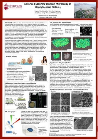
1. Bacteria
volume
percentage:
19%
Bacteria
coverage
percentage:
14%
Advanced
Scanning
Electron
Microscopy
of
Staphylococcal
Biofilms
Jingzhe
Niu,
Jiahua
Gu,
Yong
Wu,
Jing
Liang,
Alex
(Tseng-‐Ming)
Chou
and
MaIhew
Libera
Stevens
InsNtute
of
Technology
Hoboken,
New
Jersey,
U.S.A.
ABSTRACT: Biofilms are three-dimensional communities of bacteria distributed in
a highly hydrated extracellular matrix (ECM). They have structure over multiple
length scales ranging from nanoscale to macroscale. We have used two approaches
involving scanning electron microscopy (SEM) to assess this structure.
In one, staphylococcal (ATCC 12600) biofilms are fixed, stained, and embedded in
epoxy following traditional electron-microscopy specimen-preparation methods. We
then use focused ion beam (FIB) tomography to visualize the 3-D biofilm structure. In
a volume of 15 µm x 18 µm x 9 µm, for example, we find that the biofilm-substrate
interface is only partially covered by bacteria. In the total volume there are 866
individual bacteria, and these occupy roughly 19% of the sample volume, the
remaining portion presumably being previously occupied by hydrated ECM and water
channels prior to fixing and embedding.
In order to preserve the hydrated biofilm, we have used a second approach involving
high-pressure freezing (HPF) to cryo-preserve S. aureus biofilms and study their
morphology by cryo-SEM. A short sublimation period is sufficient to remove a small
portion of water and reveal both the bacteria and the ECM while still physically fixing
the exposed bacteria in a medium of amorphous ice. The bacteria are arranged in a
pseudo-close-packed array where adjacent bacteria are separated by distances on
the order of 0.1 micron or more. These bacteria are covered by a fine network of
ECM fibrils, which, in some cases, have diameters as small as 50 nm. Fully
dehydrated samples, viewed in cross section, exhibit a similar morphology that
extends in three dimensions.
Five stages of biofilm development.
From “Understanding biofilm resistance to antibacterial agents”
David Davies, Nature Reviews Drug Discovery 2, 114-122 (February 2003)
! Bacteria colonize surfaces and
develop into biofilms
! Biofilms are structured communities of bacteria,
often involving multiple types of bacteria
! Biofilms are highly hydrated with
ECM consisting of DNA/polysaccharides
! Bacteria in the biofilm state can be
highly resistant to antimicrobials
Bacterial Biofilms
EM Specimen Preparation: Heavy-Element Staining
Cryo-Fixation of Hydrated Biofilms
Cryo-fixation involves rapidly cooling a hydrated sample to amorphize the water and
immobilize the sample structure. Water crystallization must be prevented in order to
avoid introducing a range of different specimen-preparation artifacts.
At 1 atm, liquid nitrogen (LN2) boils at -196 ̊C. Hence, plunging a hydrated sample
into LN2 causes freezing. But, formation of a thin layer of gaseous nitrogen at the
sample surface inhibits efficient heat transfer. Faster cooling can be achieved by
plunging into liquid ethane, which can be cooled below its boiling temperature of -89 ̊C
by surrounding it with LN2. Formation of a gas layer is diminished, thereby increasing
the net cooling rate. However, neither approach effectively amorphizes water for
specimen thicknesses great than ~1 µm.
Substantially more effective cooling can be achieved by increasing the pressure
during quenching (high-pressure freezing: HPF). Pure water thicknesses of about 100
µm can be amorphized by this approach. Crystalline ice has a lower density than
liquid water for P < 210 MPa. Amorphous ice has about the same density as water.
Application of 210 MPa during freezing counteracts the expansion of water during
crystallization, reducing Tm
water to -22 °C. Importantly, at 210 MPa only ~1000 K/s is
sufficient to vitrify hydrated material instead of ~100,000 K/s at ambient pressure.
High-Pressure Freezing Preserves S. aureus Biofilm Structure
Top-view cryo-SEM images of S. aureus biofilms prepared by high-
pressure freezing: (A, C, E) after 20 min sublimation; and (B, D, F)
after 16 hours sublimation at -105˚C. Scale bars denote 2 µm.
F
A B
C D
E
Top View
Sapphire substrate
A B
C
D
1 µm
Sublimated for 10 min (A) or 60 min (B, C, D).
(B), (C), and (D) show higher magnification sections from the
top, middle, and bottom, respectively, of the biofilm.
Cross-sectional view
Acknowledgements
This research project has been supported by the U.S. Army Research Office through grant #W911NF-12-1-0331 and
uses instrumentation partially supported by the U.S. National Science Foundation.
Air dried
S. aureus (ATCC
12600) after 24 h
growth in TSB at
37 oC, then
rinsed, air dried,
and imaged.
Data cube volume:
18 µm x 15 µm x 9 µm
Voxel size:
10 nm x 10 nm x 20 nm
Slice thickness: 20 nm
Drying a biofilm removes a significant fraction of the biofilm volume, namely the
water, leaving a collection of bacteria agglomerated within dried and dense ECM.
Following well-established methods for biological specimen preparation, prior to
dehydration, we used glutaraldehyde to fix the biofilm structure and osmium
tetraoxide to crosslink and stain unsaturated carbon bonds. The fixed and stained
structure was then embedded in epoxy.
Sections for TEM can be cut via
room-temperature ultramicrotomy, and
the block face can be used for SEM
Focused Ion Beam (FIB) tomography uses serial 2-D
images to reconstruct a 3-D model of a sample. After
ion milling a trench on the specimen surface, an SEM
image is collected from the exposed face. The FIB is
then used to remove a thin slice of material (~2 – 20
nm thickness) from the exposed face. A next SEM
image is collected from the newly exposed face. The
process can be automated to collect 100’s of such 2-
D images, which can later be rendered
computationally into a 3-D structure.
450 2-D SEM images were collected at intervals of 20 nm from an S. aureus biofilm grown 24 hours
on a polystyrene petri dish and subsequently fixed, stained, embedded, trimmed, and microtomed.
3-D reconstruction of fixed, stained, embedded S. aureus biofilm on polystyrene
5 µm
Epoxy
S. epi
Biofilm
PS
Petri Dish
Substrate
water ECM
Bacterium
Dry
Fix
Stain
Embed
Dried ECM
OsO4-stained bacterium
FIB Tomography
SEM
FIB
SEM
image
Reconstruction
1. Align slices in x,y
(cross correlation)
2. Align in z
3. Correct Tilt angle
4. Apply LUT
3-D Structure of S. aureus Biofilm
2-D SEM (EsB) image of the microtomed block face
PS
Petri
Dish
1 µm
Cryo-Plunging Induces Macrosegregation
Quenched in Liquid Ethane + Ice Sublimation
Side view Top view
S. aureus Biofilm in
Cross Section
Plunging thin hydrated specimens in a cryogen
such as LN2 or liquid ethane/propane is a
common means of freezing. In part because of
the Leidenfrost effect, where a layer of gas
insulates the hydrated specimen from the
cryogen, the thickness of hydrated specimen
that can be amorphized is typically limited to a
few microns or less. Beyond that distance
from the surface the water crystallization and
can induce a range of artifacts including
macrosegregation.
Wu, Liang, Rensing, Chou, Libera (2014), “Extracellular Matrix
Reorganization during Cryo Preparation for Scanning Electron Microscope
Imaging of S. aureus Biofilms,” Microscopy & Microanalysis: V20, 1348-1355.
For the experimental data, the location of 932
objects can be identified. Meshlab software
can then be used to recreate a model biofilm
for further quantitative analysis.
Biofilm experimental data Biofilm 3-D model
Bacteria volume: 19%
Bacteria/PS
interface coverage: 14%
*Thanks to Prof. Philippos Mordohai and Jason Gardella
from the Stevens Department of Computer Science.