Call Girls in Ramesh Nagar Delhi 💯 Call Us 🔝9953056974 🔝 Escort Service
Fibra óptica.pdf
1. Fiber optics
3.1 Introduction
Fiber-optic communication uses light signals guided through a fiber core. Fiber-optic
cables act as wave-guides for light, with all the energy guided through the central core of
the cable. The light is guided due to the presence of a lower refractive index cladding
surrounding the central core. None of the energy in the signal is able to escape into the
cladding and no energy is able to enter the core from any external sources. Therefore the
transmissions are not subject to electromagnetic interference.
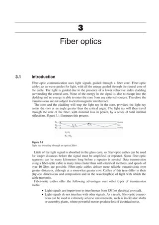
The core and the cladding will trap the light ray in the core, provided the light ray
enters the core at an angle greater than the critical angle. The light ray will then travel
through the core of the fiber, with minimal loss in power, by a series of total internal
reflections. Figure 3.1 illustrates this process.
Figure 3.1
Light ray traveling through an optical fiber
Little of the light signal is absorbed in the glass core, so fiber-optic cables can be used
for longer distances before the signal must be amplified, or repeated. Some fiber-optic
segments can be many kilometers long before a repeater is needed. Data transmission
using a fiber-optic cable is many times faster than with electrical methods, and speeds of
over 10 Gbps are possible. Fiber-optic cables deliver more reliable transmissions over
greater distances, although at a somewhat greater cost. Cables of this type differ in their
physical dimensions and composition and in the wavelength(s) of light with which the
cable transmits.
Fiber-optic cables offer the following advantages over other types of transmission
media:
• Light signals are impervious to interference from EMI or electrical crosstalk.
• Light signals do not interfere with other signals. As a result, fiber-optic connec-
tions can be used in extremely adverse environments, such as in elevator shafts
or assembly plants, where powerful motors produce lots of electrical noise.
2. Fiber optics 51
• Optical fibers have a much wider, flat bandwidth than coaxial cables and
equalization of the signals is not required.
• The fiber has a much lower attenuation, so signals can be transmitted much
further than with coaxial or twisted-pair cable before amplification is
necessary.
• Optical fiber cables do not conduct electricity and so eliminates problems of
ground loops, lightning damage and electrical shock when cabling in high-
voltage areas.
• Fiber-optic cables are generally much thinner and lighter than copper cable.
• Fiber-optic cables have greater data security than copper cables.
• Licensing is not required, although a right-of-way for laying the cable is
needed.
3.2 Fiber-optic cable components
The major components of a fiber-optic cable are the core, cladding, buffer, strength members,
and jacket, as shown in Figure 3.2. Some types of fiber-optic cable even include a conductive
copper wire that can be used to provide power to a repeater.
Figure 3.2
Fiber-optic cable components
3.2.1 Fiber core
The core of a fiber-optic telecommunications cable consists of a glass fiber through
which the light signal travels. The most common core sizes are 50 and 62.5 μm
(microns), which are used in multimode cables. 8.5 micron fibers are used in single-
mode systems.
3. 52 Practical Industrial Data Communications
3.2.2 Cladding
The core and cladding are actually manufactured as a single unit. The cladding is a
protective layer with a lower index of refraction than the core. The lower index means
any light that hits the core walls will be redirected back to continue on its path. The
cladding diameter is typically 125 microns.
3.2.3 Fiber-optic buffer
The buffer of a fiber-optic cable is made of one or more layers of plastic surrounding the
cladding. The buffer helps strengthen the cable, thereby decreasing the likelihood of micro
cracks, which can eventually break the fiber. The buffer also protects the core and cladding
from potential invasion by water or other materials in the operating environment. The
buffer typically doubles the diameter of the fiber.
A buffer can be tight or loose, as shown in Figure 3.3. A tight buffer fits snugly around
the fiber. A tight buffer can protect the fibers from stress due to pressure and impact, but
not from changes in temperature. A loose buffer is a rigid tube of plastic with one or more
fibers (consisting of core and cladding) running through it. The fibers are longer than the
tube so that the tube takes all the stresses applied to the cable, isolating the fiber from
these stresses.
Figure 3.3
Fiber housing types
3.2.4 Strength members
Fiber-optic cable also has strength members, which are strands of very tough material
(such as steel, fiberglass, or Kevlar) that provide tensile strength for the cable. Each of
these materials has advantages and drawbacks. For example, steel conducts electricity
making the cable vulnerable to lightning, which will not disrupt an optical signal but may
seriously damage the cable or equipment.
3.2.5 Cable sheath
The sheath of a fiber-optic cable is an outer casing that provides primary mechanical
protection, as with electrical cable.
4. Fiber optics 53
3.3 Fiber-optic cable parameters
3.3.1 Attenuation
The attenuation of a multimode fiber depends on the wavelength and the fiber construction,
and range from around 3 to 8 dB/km at 850 nm and 1 to 3 dB/km at 1300 nm. The
attenuation of single-mode fiber ranges from around 0.4 to 0.6 dB/km at 1300 nm and
0.25 to 0.35 dB/km at 1550 nm.
3.3.2 Diameter
The fiber diameter is either 50 or 62.5 microns for multimode fiber or 8.5 microns for
single mode.
• Multimode fibers (50 or 62.5 micron): In multimode fibers, a beam of light has
room to follow multiple paths through the core. Multiple modes in a transmission
produce signal distortion at the receiving end, due to the difference in arrival time
between the fastest and slowest of the alternate light paths.
• Single mode fibers (8.5 micron): In a single-mode fiber, the core is so narrow
that the light can take only a single path through it. Single-mode fiber has the
least signal attenuation, usually less than 0.5 dB/km. This type of cable is the
most difficult to install, because it requires precise alignment of the system
components and the light sources and detectors are very expensive. However,
transmission speeds of 50 Gbps and higher is possible.
3.3.3 Wavelength
Fiber-optic systems today operate in one of the three-wavelength bands viz. 850 nm,
1300 nm, or 1550 nm. The shorter wavelengths have a greater attenuation than the longer
wavelengths. Short-haul systems tend to use the 850 or 1300 nm wavelengths with the
multimode cable and light emitting diode (LED) light sources. The 1550 nm fibers are
used almost exclusively with the long-distance systems using single-mode fiber and laser
light sources.
3.3.4 Bandwidth
The bandwidth of a fiber is given as the range of frequencies across which the output
power is maintained within 3 dB of the nominal output. It is quoted as the product of the
frequencies of bandwidth multiplied by distance, for example, 500 MHz km. This means
that 500 MHz of bandwidth is available over a distance of one kilometer, or 100 MHz of
bandwidth over 5 km.
3.3.5 Dispersion
Modal dispersion is measured as nanoseconds of pulse spread per kilometer (ns/km). The
value also imposes an upper limit on the bandwidth, since the duration of a signal must be
larger than the nanoseconds of a tail value. With step-index fiber, expect between 15 and
30 ns/km. Note that a modal dispersion of 20 ns/km yields a bandwidth of less than 50 Mbps.
There is no modal dispersion in single-mode fibers, because only one mode is involved.
Chromatic dispersion occurs in single-mode cables and is measured as the spread of the
pulses in picoseconds for each nanometer of spectral spread of the pulse and for each
kilometer traveled. This is the only dispersion effect in single-mode cables and typical
values are in the order of 3.5 ps/nm km at 1300 nm and 20 ps/nm km at 1550 nm.
5. 54 Practical Industrial Data Communications
3.4 Types of optical fiber
One reason optical fiber makes such a good transmission medium is because the different
indices of refraction for the cladding and core help to contain the light signal within the
core, producing a waveguide for the light. Optical fiber can be constructed by changing
abruptly from the core refractive index to that of the cladding, or this change can be made
gradually (Figure 3.4). The two main types of multimode fiber differ in this respect.
• Step-index cable: Cable with an abrupt change in refraction index is called
step-index cable. In step-index cable, the change is made in a single step.
Single-step multimode cable uses this method, and it is the simplest, least
expensive type of fiber-optic cable. It is also the easiest to install. The core is
usually 50 or 62.5 microns in diameter; the cladding is normally 125 microns.
The core width gives light quite a bit of room to bounce around in, and the
attenuation is high (at least for fiber-optic cable); between 10 and 50 dB/km.
Transmission speeds up to 10 Mbps over 1 km are possible.
• Graded-index cable: Cable with a gradual change in refraction index is called
graded-index cable, or graded-index multimode. This fiber-optic cable type has
a relatively wide core, like single-step multimode cable. The change occurs
gradually and involves several layers, each with a slightly lower index of
refraction. A gradation of refraction indexes controls the light signal better than
the step-index method. As a result, the attenuation is lower, usually less than
15 dB/km. Similarly, the modal dispersion can be 1 ns/km and lower, which
allows more than ten times the bandwidth of step-index cable.
Figure 3.4
Fiber refractive index profiles
6. Fiber optics 55
• Fiber designations: Optical fibers are specified in terms of their core, cladding,
and coating diameters. For example, a 62.5/125/250 fiber has a core diameter of
62.5 microns, a cladding of 125 microns and a coating of 250 microns.
3.5 Basic cable types
There are four broad application areas into which fiber-optic cables can be classified:
aerial cable, underground cable, sub-aqueous cable, and indoor cable. The special
properties required for each of these applications will now be considered. Note that this
list is not all encompassing, and that some specialized cables need to combine the features
of several of these classes.
3.5.1 Aerial cable
Aerial cables are literally exposed to the elements, more than any other application, and as
such are exposed to many external forces and hazards. Aerial cables are installed between
poles with the weight of the cable continuously supported by usually a steel messenger wire
to which the cable can be directly lashed, or by the strength members integral to the cable
construction. Greatly increased tensile forces can be produced by the effects of combined
wind and ice loadings. Other considerations are the wide variations in temperature to which
the cable may be subjected, affecting the physical properties of the fibers and the
attenuation of the fibers. The longitudinal cable profile is important for reducing the wind
and ice loadings of such cables. Moisture barriers are essential, with jelly-filled, loose
buffered fiber cable configurations being predominant. Any water freezing within the fiber
housings would expand and could produce excessive bending of fibers.
The cable sheath material is required to withstand the extremes of temperature and the
intense ultraviolet light exposure from continuous exposure to sunlight. UV-stabilized
polyethylene is frequently used for this purpose.
The installed span length and sag requirements are important design parameters
affecting the maximum cable tension, and which dictates the type of cable construction to
be used. Short-span cables have less-stringent tension requirements, which can be met by
the use of integral Kevlar layers, whereas long-span cables may need to utilize multiple-
stranded FRP rods to meet the required maximum tensions.
Advantages of aerial cable
• Useful in areas where it may be very difficult or too expensive to bury the cable
or install it in ducts.
• Also useful where temporary installations are required.
Disadvantages
• System availability is not as high as for underground cables. Storms can disrupt
these communication bearers, with cables damaged by falling trees, storm
damage, and blown debris. Roadside poles can be hit by vehicles and frustrated
shooters seem unable to miss aerial cables!
3.5.2 Underground cable
Underground cables experience less environmental extremes than aerial cables. Cables are
usually pulled into ducts or buried directly in the ground, with the cables being placed in deep
narrow trenches, which are backfilled with dirt or else ploughed directly into the ground.
7. 56 Practical Industrial Data Communications
Cable type
Loose buffering, using loose tube or slotted core construction, is generally used to isolate
fibers from external forces including temperature variations.
Advantages
• Usually the most cost-effective method of installing cables outdoors
• Greater environmental protection than aerial cable
• Usually more secure than aerial cable.
Disadvantages
• Can be disrupted by earthworks, farming, flooding, etc.
• Rodents biting cables can be a problem in some areas. This is overcome with the
use of steel tape armor or steel braid, or the use of a plastic duct of more than
38 mm OD for all dielectric cable installations. Also the use of Teflon coatings
on the sheath make the cable too slippery for the rodent to grip with its teeth.
3.5.3 Sub-aqueous cables
Sub-aqueous cables are basically outdoor cables designed for continuous immersion in
water. While international telecommunications carriers use the most sophisticated cables
for deep ocean communications, there are practical applications for sub-aqueous cables
for smaller users. These include cabling along or across rivers, lakes, water races, or
channels, where alternatives are not cost effective. Sub-aqueous cable is a preferred
option for direct buried cabling in areas subjected to flooding or with a high water table,
where, for example, if the cable were buried at, say, 1 m depth, it would be permanently
immersed in water. These cables are essentially outdoor cable constructions incorporating
a hermetically sealed unit, using a welded metallic layer, and encasing the fiber core.
Advantages
• Cheaper installation in some circumstances.
Disadvantages
• Unit cost of cable is higher.
3.5.4 Indoor cables
Indoor cables are used inside buildings and have properties dictated by the fire codes. Such
cables need to minimize the spread of fires, and must comply with your relevant local fire
codes, such as outlined in the national electrical codes (NEC) in USA. Outdoor cables
generally contain oil-based moisture-blocking compounds like petroleum jelly. These
support combustion and so, their use inside buildings is strictly controlled. Outdoor cables
are frequently spliced to appropriate indoor cables close to the building entry points, to
avoid the expense of encasing long runs of outdoor cable inside metallic conduit.
The fiber in indoor cables and the indoor cable itself is usually tightly buffered, as was
discussed in Section 3.2. The tight buffer provides adequate water resistance for indoor
applications, but such cables should not be used for long outdoor cable runs. The buffered
fibers can be given sufficient strength to enable them to be directly connected to
equipment from the fiber structure without splicing to patch cords.
8. Fiber optics 57
3.6 Connecting fibers
This section will identify the main issues involved in connecting fibers together and to
optical devices, such as sources and detectors. This can be done using splices or
connectors. A splice is a permanent connection used to join two fibers and a connector is
used where the connection needs to be connected and disconnected repeatedly, such as at
patch panels. A device used to connect three or more fibers or devices is called a coupler.
3.6.1 Connection losses
The main parameter of concern when connecting two optical devices together is the
attenuation – that fraction of the optical power lost in the connection process. This
attenuation is the sum of losses caused by a number of factors, the main ones being:
• Lateral misalignment of the fiber cores
• Differences in core diameters
• Misalignment of the fiber axes
• Numerical aperture differences of the fibers
• Reflection from the ends of fibers
• Spacing of the ends of the fibers
• End finish and cleanliness of fibers.
The most important of these loss mechanisms involved in connecting multimode fibers
is the axial misalignment of the fibers.
With connectors, the minimum loss across the glass/air interface between them will
always be about 0.35 dB, unless index-matching gel is used.
3.6.2 Splicing fibers
Two basic techniques are used for splicing of fibers: fusion splicing and mechanical splicing.
With the fusion splicing technique, the fibers are welded together, requiring expensive
equipment, but will produce consistently lower loss splices with low consumable costs. With
mechanical splicing, the fibers are held together in an alignment structure, using an adhesive
or mechanical pressure. Mechanical splicers require lower capital cost equipment but have a
high consumable cost per splice.
• Fusion splicing: Fusion splices are made by melting the end faces of the
prepared fibers and fusing the fibers together. Practical field fusion splicing
machines use an electric arc to heat the fibers. Factory splicing machines often
use a small hydrogen flame. The splicing process needs to precisely pre-align
the fibers, then heat their ends to the required temperature and move the
softened fiber ends together sufficiently to form the fusion joint, whilst
maintaining their precise alignment. Fusion splices have consistently very low
losses and are the preferred method for joining fibers, particularly for single-
mode systems. Modern single-mode fusion splicers utilize core alignment
systems to ensure the cores of the two fibers are precisely aligned before
splicing.
• Mechanical splicing: Mechanical splicing involves many different approaches
for bringing the two ends of the fibers into alignment and then clamping them
within a jointing structure or gluing them together. Mechanical splices
generally rely on aligning the outer diameters of the fiber cladding and assumes
that the cores are concentric with the outside of the cladding. This is not always
9. 58 Practical Industrial Data Communications
the case, particularly with single mode fibers. Various mechanical structures
are used to align the fibers, including V grooves, sleeves, 3 rods and various
proprietary clamping structures.
3.6.3 Connectors
Connectors are used to make flexible interconnections between optical devices.
Connectors have significantly greater losses than splices since it is much more difficult to
repeatedly align the fibers with the required degree of precision. Active alignment, as was
used to minimize some splice losses, is not possible. Axial misalignment of the fibers
contributes most of the losses at any connection, consequently connector loss can be
expected to be in the range from 0.2 to over 3 dB.
Most connector designs produce a butt joint with the fiber ends as close together as
possible. The fiber is mounted in a ferrule with a central hole sized to closely match the
diameter of the fiber cladding. The ferrule is typically made of metal or ceramic and its
purpose is to center and align the fiber as well as provide mechanical protection to the
end of the fiber. The fiber is normally glued into the ferrule then the end cut and polished
to be flush with the face of the ferrule. The two most common connectors are the SC and
ST, as detailed below. Many new proprietary connectors are now available for different
types of equipment.
• SC connector: This is built with a cylindrical ceramic ferrule which mates with
a coupling receptacle. The connector has a square cross section for high packing
density on equipment, and has a push–pull latching mechanism. The ISO and
TIA have adopted a polarized duplex version as standard and this is now being
used as a low-cost FDDI connector. The SC connector has a specified loss of less
than 0.6 dB (typically 0.3 dB) for both single mode and multimode fibers and a
typical return loss of 45 dB.
• ST connector: The ST connector is shown in Figure 3.5. This is an older
standard used for data communications. This is also built with a cylindrical
ceramic ferrule which mates with a coupling receptacle. The connector has a
round cross section and is secured by twisting to engage it in the spring-loaded
bayonet coupling. Since it relies on the internal spring to hold the ferrules
together, optical contact can be lost if a force of greater than about 1 kg is
applied to the connector.
Figure 3.5
ST connector
10. Fiber optics 59
3.6.4 Connector handling
Most fiber-optic connectors are designed for indoor use. Connectors for outdoor use
require to be hermetically sealed. It is very important to protect the optical faces of the
connectors from contamination. The optical performance can be badly degraded by the
presence of dirt or dust on the fiber ends. A single dust particle could be 10 microns in
diameter, which would scatter or absorb the light and could totally disrupt a single-mode
system. Connectors and patch panels are normally supplied with protective caps. These
should always be fitted whenever the connectors are not mated. These not only protect
from dust and dirt, but also provide protection to the vulnerable, polished end of the fiber.
Compressed air sprays are available for cleaning connectors and adapters, without
needing to physically touch the mating surfaces.
Take care not to touch the end of the connector ferrules as the oil from your fingers can
cause dirt to stick to the fiber end. Clean connectors with lint-free wipes and isopropyl
alcohol.
Durability of the connectors is important throughout their lifetime. Typical fiber
connectors for indoor use are specified for 500 to 1000 mating cycles, and the attenuation
is typically specified not to change by more than 0.2 dB throughout that lifetime.
Repeated connection and disconnection of the connectors can wear the mechanical
components and introduce contamination to the optical path.
3.6.5 Optical couplers
Optical couplers or splitters and combiners are used to connect three or more fibers or other
optical devices. These are devices which split the input power to a number of outputs.
While the splitting of the light is done passively, active couplers include optical amplifiers,
which boost the signal before or after the splitting process. Coupler configuration depends
on the number of ports and whether each of these are unidirectional, so called directional
couplers, or bi-directional. Most couplers are found within the equipment for monitoring
purposes.
3.7 Splicing trays/organizers and termination cabinets
This section looks at the different types of storage units that are used for housing optical
fiber splices and end of cable terminations.
3.7.1 Splicing tray
Splices are generally located in units referred to as ‘splicing centers’, ‘splicing trays’ or
‘splicing organizers’. The splicing tray is designed to provide a convenient location to
store and to protect the cable and the splices. They also provide cable strain relief to the
splices themselves.
Splicing trays can be located at intermediate points along a route where cables are
required to be joined or at the termination and patch panel points at the end of the cable
runs.
The incoming cable is brought into the splicing center where the sheath of the cable is
stripped away. The fibers are then looped completely around the tray and into a splice
holder. Different holders are available for different types of splices. The fibers are then
spliced onto the outgoing cable if it is an intermediate point or on to pigtails if it is a
termination point. These are also looped completely around the tray and then fed out of
the tray. A typical splicing tray is illustrated in Figure 3.6.
11. 60 Practical Industrial Data Communications
Figure 3.6
A typical splicing tray
The cables are physically attached to the splice tray to provide strain relief. The cables
normally enter the tray on one side only to facilitate moving the tray/joint enclosure to a
more accessible jointing location. The fibers are looped completely around the tray to
provide slack, which may be required to accommodate any changes in the future, and also
to provide tension relief on the splices.
Each splice joint is encased in a splice protector (plastic tube) or in heat shrink before it
is clipped into the holder.
Splicing trays are available that have patching facilities. This allows different fibers to
be cross-connected and to be looped back for testing purposes.
3.7.2 Splicing enclosures
The splicing trays are not designed to be left in the open environment and must be placed
in some type of enclosure. The enclosure that is used will depend on the application. The
following are examples of some enclosures used for splicing trays.
• Direct buried cylinders: At an intermediate point where two cables are joined
to continue a cable run, the splices can be directly buried by placing the splice
trays in a tightly sealed cylindrical enclosure that is generally made from heavy
duty plastic or aluminum. The container is completely sealed from moisture
ingress and contains desiccant packs to remove any moisture that may get in.
A typical direct buried cylinder is illustrated in Figure 3.7. Note that the cables
normally enter the enclosure at one end only to allow the enclosure to be lifted
from the ground for easier splicing access.
Figure 3.7
Direct buried splicing enclosure
12. Fiber optics 61
• Termination cabinets: At junction points where a lot of cables meet, the
splicing trays are stored in a larger wall-mounted cabinet (approximately 500 ×
500 × 100 mm) with a hinged door. For outdoor use, the cabinets must be
sealed against bad weather conditions. Figure 3.8 illustrates a splicing tray in a
termination cabinet.
• Patch panels and distribution frames: Splice trays can be installed in the back
of patch panels and distribution frames used for connection of patch cords to
the main incoming cable.
3.7.3 Termination in patch panels and distribution frames
There are three main methods of connecting an incoming cable into a patch panel or
distribution frame. Firstly, if the incoming cable contains fibers that have a large
minimum bending radius, then it is recommended to splice each fiber to a fiber patch cord
that has a smaller bending radius. This reduces undue stress on the incoming fibers but
does introduce small losses into the link. This also replaces the more fragile glass of the
incoming cable with the more flexible and stronger glass of the patch cords. This is
illustrated in Figure 3.8.
Figure 3.8
Termination cabinet for splicing trays
The second method is to place the fibers from the incoming cable into a breakout unit.
The breakout unit separates the fibers and allows a plastic tube to be fitted over the
incoming fibers to provide protection and strength as they are fed to the front of the patch
panel. Note there are no splices, which therefore keep losses to a minimum. This is
illustrated in Figure 3.9.
13. 62 Practical Industrial Data Communications
Figure 3.9
Patch panel with break out box
If the incoming cable contains tight buffered fibers that are flexible and strong, then
they can be taken directly to the front of the patch panel. This is referred to as direct
termination, and is illustrated in Figure 3.10.
Figure 3.10
Direct termination of cables in a patch panel
3.8 Troubleshooting
3.8.1 Introduction
This section deals with problems of fiber-optic cables. Problems can be caused by poor
installation practices, where fibers are subjected to excessive tension or bending forces.
This section also deals with the basic methods of testing fibers and how to locate faults on
fiber-optic systems.