More Related Content
Similar to Introduction to Worm Gearing
Similar to Introduction to Worm Gearing (20)
Introduction to Worm Gearing
- 1. © James K. Simonelli 3/6/2011 All Rights Reserved Page 1 of 7
Introduction to Worm Gearing
Worm gears are among the oldest types of gearing, but that does not mean they are obsolete,
antiquated technology. The main reasons for the bad experiences some engineers have with worm
gearing are misapplication and misuse. No form of gearing works for every application. Strengths
and weaknesses versus the application must be weighed to decide which form of gearing to use.
For proper application and operation of worm gears, certain areas that may differ from other types
of gearing need to be addressed.
The Basics
Worm gear reducers are quiet, compact, and can have large reduction ratios in a single stage.
The ideal ratio range for worm gearing is 5:1 to 75:1. This is the general range for most catalog
reducers. Ratios of 3:1 to 120:1 are practical and have applications that are very successful. For
ratios below 3:1, worm gearing is not a practical solution for most applications, and other forms of
gearing should be considered. Worm gearing for ratios above the ranges mentioned are generally
more practical as part of a multistage reduction.
In service, worm gears survive large overloads and high shocks. When properly applied, worm
gearing can offer excellent performance and cost savings. Worm gearing has an inherent 200%
overload (i.e., 3x rating) capacity in its rating. Other forms of gearing do not have this built-in
service factor. Therefore a lower service factor can be used when sizing a worm gear set.
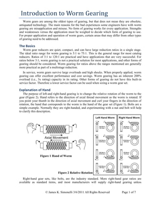
Explanation of Hand
The purpose of left-and right-hand gearing is to change the relative rotation of the worm to the
gear (Figure 2). Hand refers to the direction of axial thread movement as the worm is rotated. If
you point your thumb in the direction of axial movement and curl your fingers in the direction of
rotation, the hand that corresponds to the worm is the hand of the gear set (Figure 1). Bolts are a
simple example. Normally they are right-handed, and experimenting with a nut and bolt will help
to clarify this description.
Figure 1 Hand of Worm
Figure 2 Relative Rotation
Right-hand gear sets, like bolts, are the industry standard. More right-hand gear ratios are
available as standard items, and most manufacturers will supply right-hand gearing unless
- 2. © James K. Simonelli 3/6/2011 All Rights Reserved Page 2 of 7
otherwise specified. This does not mean there is a flaw in left-hand gearing, but left-hand ratios
may not be as readily available.
Back Driving
Running a worm gear set with the gear (worm wheel) as the input member is commonly called
back driving. Back drive efficiency of a worm gear set is lower than its forward drive efficiency.
By varying design, the back drive efficiency can be reduced to zero, as in a self-locking or
irreversible gear set. If the gear tries to drive the worm, internal friction causes the mesh to lock.
No matter how much torque is applied to the gear shaft, mesh friction increases proportionally,
preventing rotation. This is the same principle that keeps a nut and bolt from unscrewing under an
applied tension load.
Back driving can occur in many applications. A
worm gear speed increaser is the most obvious, but
it is rarely used because of its low efficiency. It
also occurs in lifting applications, such as cranes,
hoists, and crank arms. When lowering the load,
the gear is the input member. Worm rotation
controls the rate of descent. Also, during braking or
coast-down, the momentum of a device will back
drive a worm.
A self-locking worm gear can be designed by
making the lead angle less than the friction angle,
which is defined as the arc tangent of the
coefficient of friction. The static coefficient of
friction is .20 to .15, equating to a friction angle of
11.3 to 8.5. Vibration in a non-rotating gear set
can induce motion in the tooth contact. The mesh
velocity is zero, but the tooth contact is dynamic.
At a mesh velocity of zero, the theoretical dynamic
coefficient of friction is .124, or a friction angle of
7.0. To provide a safety factor, a 5.0 lead angle is
recommended as the upper limit of self-locking,
and a 15.0 lead angle is recommended as the lower
limit to assume a worm gear will back drive.
Contrary to popular belief a self-locking
worm gear set once in motion will coast due
to dynamic effects. Back drive efficiency
decreases with decreasing speed. The slope
of this curve is exponential and is affected
by the lead angle (Figure 3).
This factor should be considered when
sizing a brake and its rate of application.
Often a brake placed on the worm can be
smaller than normally anticipated. Using a
brake on self-locking designs must be
thoroughly analyzed. Most brakes have an
increasing torque rate when applied. Also,
the efficiency will be decreasing during slow
down. This double effect can cause the
0%
10%
20%
30%
40%
50%
60%
70%
80%
90%
100%
0.01 1 100 10000
Efficiency
Rubbing Velocity
Worm Lead
Angles
45
30 20
15
10
7.5
5
Figure 3 Efficiency versus Rubbing Velocity
(rpm)WormofSpeedRotational
(inch)WormofDiameterPitch
(ft/min)VelocityRubbingMesh
2.7183)(i.e.LogNatural
FrictionoftCoefficien
AngleFriction
AngleLead
12
4][eq.
0.012
450.0110.0103.0
10for3b][eq.
645.0074.0124.0
10for3a][eq.
2][eq.
1][eq.
1
P
P
D
e
Cos
D
e
e
Tan
Tan
Tan
Efficency
- 3. © James K. Simonelli 3/6/2011 All Rights Reserved Page 3 of 7
braking torque to rise at a surprising rate, causing a sudden stop. High inertial loads with self-
locking designs should have controlled motor speed ramp down for braking.
On the other hand, back drive efficiency increases with increasing speed. Therefore a constant
back driving torque restrained only by a worm gear will have a rate of acceleration that increases
exponentially. This is a very important point to remember when designing hoists. Unless it is
properly designed, relying solely on self-locking to suspend a load may be dangerous. The load
may stay suspended until an outside influence starts a vibration in the gear mesh. Initially, the load
will creep slowly. As it falls, it accelerates at an exponentially increasing rate.
Since many factors influence the coefficient of friction, gear set designs should be tested for
their back drive suitability. Break-in of a gear set will reduce the coefficient of friction. This may
make a gear set self-locking when it is new and not self-locking after use. Also, synthetic lubricants
can have an effect on the coefficient of friction and may be used in the field without the knowledge
of the gear designer.
If self-locking is critical to safety, a brake or “back stop” should be used. A backstop is a clutch
device that permits rotation in one direction only. It is sometimes referred to as a “Sprag” or “cam
clutch” and is commonly used on conveyors that lift material to prevent reversal if power is lost.
Pitting
Gear tooth-pitting results from the combination of several forces. Normal force (referring to a
direction 90 to the tooth surface) at the contact point produces Hertzian stress. Friction produces a
tangential force, also inducing stress. Friction also generates heat. Temperature at the contact point
is much higher than the surrounding area. Differential thermal expansion (the phenomenon that can
cause a glass to break when a hot liquid is poured into it) is the third factor inducing stress.
Constant cycling as the tooth goes through the mesh can cause a surface fatigue crack. Oil in the
gear mesh is under extreme pressure from contact forces. The oil is forced into the fatigue crack,
and hydrostatic pressure tries to lift a piece out. Continuing cycles cause the crack to encircle the
high stress area. The crack grows deeper, until a piece literally pops out, leaving a pit.
In most gearing, a pitted tooth surface signals impending failure. For worm gearing, pitting is
part of normal operation. Corrective pitting is a break-in process. In manufacturing a worm, the
thread is generated by a continuous line that can be described by the grinding wheel. It produces a
continuous (i.e., smooth and uniform) surface curved in all three planes. The gear is hobbed by a
gashed cutting tool that is in effect a worm having a discontinuous or interrupted surface. It
produces gear teeth that have a series of short flats or discontinuous surfaces that approximate the
desired tooth form. Because of the flats, the gear tooth form is imperfect. Where tow flats join there
must be a peak. At such a point, the contact street would be infinite if deformation id not occur.
The break-in process is the gear tooth form being improved by the worm. This is done by elastic
or inelastic deformation, wearing away the high spots or pitting them away. After the many high
spots are either worn or pitted away. The worm rides on the larger flat areas. The pit areas retain
pools of oil, which help support the load by hydrostatic pressure and aid in lubrication. Corrective
pitting ceases after a sufficient area has been developed to sustain the load and normal wear takes-
over. A new worm gear will pit at an alarming rate, and then quickly stop. No additional pitting
will occur for a long time. Then the surface will again pit rapidly and quickly stop, the cycle
recurring throughout the life of the gear.
Destructive pitting is a case of the gear not being able to correct itself enough to support the
imposed load. It is the result of overload, improper gear adjustment, improper tooth profile, or
improper lubrication. In this case, pitting continues until the gear tooth surfaces are completely
destroyed. This is not a common problem, because most errors large enough to cause failure will
normally show up as the gearbox overheating.
- 4. © James K. Simonelli 3/6/2011 All Rights Reserved Page 4 of 7
Materials
Worm gearing has a high sliding component in its tooth meshing action. Sliding contact
materials are selected to make one member hard and strong and the other soft and ductile. Friction
is generally proportional to the combined hardness of the mating surfaces. Two hard surfaces
cannot deform to broaden the contact area and distribute the contact stress. By hardening only one
part and having the other ductile, the combined hardness is increased, while still being able to
distribute stress. Also, using dissimilar hardness reduces the chance for galling. Steel and bronze
have been the materials of choice because they balance strength, ductility, lubricity, and heat
dissipation. Shaft bushings are common examples of sliding components using this arrangement.
The worm is the hard member, and the gear is the
ductile member. There are several reasons for this
arrangement. Contact stress in both members is equal.
The worm goes through more contact cycles because
of the ratio of the gear set. Compared to steel, bronze
has a lower strength, a lower endurance ratio, and a
higher number of cycles required for infinite life.
Figure 4 uses these factors in a generalized,
theoretical S-N curve. Stress levels that have a finite
life for bronze would have an infinite life for steel.
Since the bronze will fail at a fewer cycles, it is used
for the member requiring the fewest cycles.
Gear mesh reaction forces are equal and opposite
in both members. The worm is much smaller in
diameter than the gear and has a greater span between supports. Therefore bending stress is greater
in the worm, requiring it to be made from the stronger material.
Manufacturing methods also play a part in material choice. Grinding is generally used for
accurate finish of high-hardness, heat-treated steels. Grinding the worm is a simple process, using
the flank of a straight-sided grinding wheel. Grinding the gear requires a complicated process using
a form dressed grinding wheel and a three-axis grinder.
Tin bronze has proved to be the most successful alloy for worm gears. It has a low coefficient of
friction and a low rate of wear. Good heat conduction carries away heat generated in the mesh and
dissipates it throughout the gear. Aluminum bronzes have higher strength, but also a higher
coefficient of friction. A less obvious disadvantage of the higher strength alloys is lower ductility.
Theoretical contact between a worm and gear is a line. In practice, the bronze deflects under load
broadening the contact line to an area. The material deflects until the contact area broadens enough
to support the load. A low-ductility material may have localized failure before reaching a large
enough area. Small contact areas of a lower ductility material have higher localized contact
temperatures, which further increase the sub-surface stresses.
The unique properties of tin bronze can be traced to its grain structure. When the bronze
solidifies partial segregation of the copper and tin occurs. High tin areas or grains are commonly
called the delta phase. Hardness of the delta phase is approximately 320 Brinell. The high copper
matrix supporting it is approximately 145 Brinell. The hard grains provide wear resistance and help
reduce friction. The softer matrix allows surface deformation to distribute stress. A simple model
would be to picture marbles (delta phase) imbedded in clay (matrix).
Alternate gear materials may increase certain properties, but losses in others will tend to make
them unsuitable for general use. For special applications bronze alloys other than tin bronze may
perform better. Gear materials, such as cast iron, plastic, and even steel, have worked very well in
Figure 4 Generalized S-N CurveStress
Cycles
Steel
Bronze
Finite Life for Bronze
Infinite Life for Steel
- 5. © James K. Simonelli 3/6/2011 All Rights Reserved Page 5 of 7
certain applications each application must be thoroughly analyzed by a gear engineer before
selecting alternate materials.
Worms are generally made from an alloy steel. Steel worms can be divided into hardened and
non-hardened. Hardened worms are superior in most applications. When surface hardness of
approximately 58Rc is used, several benefits are gained. Material strength is increased, friction is
lowered, and wear is reduced. Often a worm can be reused after the gear has worn out.
Non-hardened refers to the surface being lower than the typical 58 Rc. Non-hardened worms
may actually have a heat treatment to bring up the core hardness for increased strength. In
industrial applications, a core hardness of 300 Brinell is typical. Non-hardened worms are useful in
applications with low continuous power and very high peak or shock loads. These applications are
most often machine adjustments or mechanisms that are infrequently activated. Heat treating for
increased surface hardness may be eliminated in low power applications to decrease cost. If a
worm is used with a cast iron or steel gear, it should be non-hardened.
Backlash Measurement
Backlash is the measure of the free clearance between the worm and the gear teeth. Locking the
worm against rotation, setting a dial indicator on a gear tooth at the pitch radius, and rocking the
gear back and forth does measurement. The total indicator reading is the measurement of backlash.
Locking the gear and measuring worm rotation does not measure backlash. In an assembled unit
where the gear teeth are not readily accessible, backlash can be approximated by placing the
indicator on any convenient point that is fixed to the gear, such as a shaft keyway or coupling. This
measurement must be multiplied by the ratio of the gear pitch radius to the measurement radius.
Note that if the selected point is on the radius smaller than the pitch radius a multiplication of
measurement error will occur.
Lubrication
Worm gearing has a high slide-to-roll ratio when compared to other types of gearing. Because
of a high sliding component, it relies heavily on the generation of an oil film between the worm
and gear. The oil film produces an effect similar to what happens when a speeding car hits a rain
puddle. The car tire has a tendency to float on a wedge of water. In a car this is called
hydroplaning; in gears it is called elasto-hydrodynamic lubrication (EHL). This is a simplistic
description with other modes of lubrication coming into play, depending on conditions, but it gives
the general idea.
For EHL to be the only lubrication mode, it must generate a film thickness greater than the
surface roughness of the contacting parts. Film thickness is proportional to the sliding velocity and
lubricant viscosity and inversely proportional to the unit load. High unit loads possible at the
relatively low speed of worm gearing requires a very high viscosity lubricant. Viscosities of over
400 cSt at 40C are normally used to prevent premature wear and high contact temperatures. Under
high loads the film can collapse, causing the surfaces to contact. This is called “boundary
lubrication.” In this lubrication mode, other properties (i.e., lubricity or slipperiness) of the
lubricant become more important than the viscosity. In a worm gear set, a mixture of EHL and
boundary lubrication is at work.
A satisfactory lubricant for most average applications is an AGMA 7 compounded oil. Low
speeds require the higher viscosity of AGMA 8 compounded oil. Both are petroleum-based mineral
oils compounded with 3% to 10% fatty oils. These lubricants are sometimes referred to as steam
cylinder oils. The compounded oil provides lower friction and better wear characteristics than a
- 6. © James K. Simonelli 3/6/2011 All Rights Reserved Page 6 of 7
straight mineral oil. At the high pressures and temperatures in the contact area, a chemical reaction
occurs on the tooth surface, forming a protective skin.
Extreme pressure oils (EP oils) are another type of lubricant that uses a surface acting
chemistry. Most EP oils use sulfur, phosphorus, and/or chlorine additives, and are designed to work
in steel-on-steel applications. When these oils are used with bronze under high temperature and
pressure, conditions common in the mesh contact, the chemical reaction can go awry. The surface
of the bronze can begin to flake off, causing massive wear, and inter-granular stress corrosion can
cause the teeth to break. There are EP oils designed for use with bronze that use a different additive
package, and in certain applications a standard EP oil may work very well. When selecting an EP
oil for bronze gearing make sure it was carefully reviewed.
Synthetic lubricants are also very common. They are more viscosity-temperature stables than
mineral oils. This allows one lubricant to provide adequate service over a broader temperature
range. They have longer service life, reducing the number of oil changes required. They reduce
wear and friction, increasing gearbox life. Efficiency increases of 20% of the lost power are
possible. Under severe conditions properly selected synthetic oils are outstanding. Many
companies have found cost advantages using the more expensive synthetic oil for normal
applications.
Contact Pattern
The area of contact between the worm and the gear is the contact pattern. The ideal contact
pattern uses 90% of the full face with the remaining 10% open on the side where the worm enters
contact with the gear. This gives maximum contact while allowing oil to be dragged in for
lubrication. If the entering side has contact the oil will be wiped off the worm as is rotates into
mesh. Without oil being drawn in the gear set will not generate an oil film. This will cause
overheating and rapidly fail (see Lubrication section).
Figure 5 No Load Pattern Figure 6 Full Load Pattern Figure 7 Overload Pattern
Under load the gearbox, worm and gear will deflect. These deflections cause the contact pattern
to spread across the gear face toward the entering side. To compensate for contact pattern spread
the gear can be moved axially in relation to the worm. A no-load contact pattern of approximately
30% of full face biased toward the leaving side is desirable.
Since deflections occur in opposite directions for opposite rotations the profiles of two opposing
flanks of the gear are not directly in line. They are shifted axially with respect to each other when
the gear is cut. Axial movement of the gear from 90% full face to 90% full face on the opposing
flank is the total shift. Total shift anticipates deflections that will occur from full load forward to
full load reverse.
The no load contact pattern is determined by lightly coating the worm with high spot blue (i.e.
Prussian Blue). This transfers to the gear teeth when rotated by hand. Although not required,
coating the gear with a mixture of grease and powdered orange paint pigment improves contrast
with the blue making it easier to see. It also adds some lubrication when checking very large gear
sets that may be difficult to rotate by hand. To determine the full load pattern clean all oil from the
gear teeth and paint them with layout blue. Under load the paint will quickly wear off. Do not run
- 7. © James K. Simonelli 3/6/2011 All Rights Reserved Page 7 of 7
the gearbox too long before checking the loaded pattern. Lubricating oil tends to wash off the
layout blue, especially when the oil warms up in operation.
In severe applications the fully loaded pattern should be checked. The amount of shift cut into
the gear may not be enough to compensate for overly flexible housings or loads higher than
anticipated. For one rotation applications or where loading is always on one side (ex. hoists) shift is
not of major concern as the gear and typically be shifted to favor one flank. Take care that the
worm does not lose backlash and contact both flanks under no load. That will cause excessive heat
and cause premature failure.
In most reducer designs axial gear adjustment is accomplished by shims between the gear shaft
bearing caps and the housing (Figure 8). First determine the total shims for proper bearing end
play. Then transfer shims between the bearing caps until optimum no load gear pattern is achieved.
In heavy duty applications where it is desirable to set the shaft based on the fully loaded pattern
this would is very complex. An alternate design is to have the bearings opposite the output shaft in
a carrier that can be moved without accessing the drive side (Figure 9).
Figure 8 Shift Adjustment at Both Sides
Figure 9 Shift Adjustment at One Side
About the author:
James K. Simonelli is a Licensed Professional Engineer with 30 years experience designing and
troubleshooting machine automation, heavy duty equipment and industrial products. He has a
broad background with department head roles in engineering, quality and business development in
companies varying from startups, turnarounds to Fortune 100 corporations. Mr. Simonelli has
served on committees developing industrial standards for the American Gear Manufacturers
Association and the Hydraulics Institute.
Mobile: 404-702-3050; Email: j.simonelli@att.net; Skype: jim.simonelli; Linkedin: www.linkedin.com/in/jsimonelli
Shims
ShimsShims
![© James K. Simonelli 3/6/2011 All Rights Reserved Page 2 of 7
otherwise specified. This does not mean there is a flaw in left-hand gearing, but left-hand ratios
may not be as readily available.
Back Driving
Running a worm gear set with the gear (worm wheel) as the input member is commonly called
back driving. Back drive efficiency of a worm gear set is lower than its forward drive efficiency.
By varying design, the back drive efficiency can be reduced to zero, as in a self-locking or
irreversible gear set. If the gear tries to drive the worm, internal friction causes the mesh to lock.
No matter how much torque is applied to the gear shaft, mesh friction increases proportionally,
preventing rotation. This is the same principle that keeps a nut and bolt from unscrewing under an
applied tension load.
Back driving can occur in many applications. A
worm gear speed increaser is the most obvious, but
it is rarely used because of its low efficiency. It
also occurs in lifting applications, such as cranes,
hoists, and crank arms. When lowering the load,
the gear is the input member. Worm rotation
controls the rate of descent. Also, during braking or
coast-down, the momentum of a device will back
drive a worm.
A self-locking worm gear can be designed by
making the lead angle less than the friction angle,
which is defined as the arc tangent of the
coefficient of friction. The static coefficient of
friction is .20 to .15, equating to a friction angle of
11.3 to 8.5. Vibration in a non-rotating gear set
can induce motion in the tooth contact. The mesh
velocity is zero, but the tooth contact is dynamic.
At a mesh velocity of zero, the theoretical dynamic
coefficient of friction is .124, or a friction angle of
7.0. To provide a safety factor, a 5.0 lead angle is
recommended as the upper limit of self-locking,
and a 15.0 lead angle is recommended as the lower
limit to assume a worm gear will back drive.
Contrary to popular belief a self-locking
worm gear set once in motion will coast due
to dynamic effects. Back drive efficiency
decreases with decreasing speed. The slope
of this curve is exponential and is affected
by the lead angle (Figure 3).
This factor should be considered when
sizing a brake and its rate of application.
Often a brake placed on the worm can be
smaller than normally anticipated. Using a
brake on self-locking designs must be
thoroughly analyzed. Most brakes have an
increasing torque rate when applied. Also,
the efficiency will be decreasing during slow
down. This double effect can cause the
0%
10%
20%
30%
40%
50%
60%
70%
80%
90%
100%
0.01 1 100 10000
Efficiency
Rubbing Velocity
Worm Lead
Angles
45
30 20
15
10
7.5
5
Figure 3 Efficiency versus Rubbing Velocity
(rpm)WormofSpeedRotational
(inch)WormofDiameterPitch
(ft/min)VelocityRubbingMesh
2.7183)(i.e.LogNatural
FrictionoftCoefficien
AngleFriction
AngleLead
12
4][eq.
0.012
450.0110.0103.0
10for3b][eq.
645.0074.0124.0
10for3a][eq.
2][eq.
1][eq.
1
P
P
D
e
Cos
D
e
e
Tan
Tan
Tan
Efficency](data:image/gif;base64,R0lGODlhAQABAIAAAAAAAP///yH5BAEAAAAALAAAAAABAAEAAAIBRAA7)