1. UAV – Mars Rover
Gianmarco Casiraghi, Joshua Dube’, Isaac Spence, Brock Hedlund, Tiziano Bernard
Faculty Advisors: Dr. Brian Kaplinger & Dr. Ronnal Reichard, Dept of MAE, Florida Institute of Technology
UAV Purpose
The UAV will provide aerial assistance for Team Olympus
throughout the Mars Society 2015 University Rover Challenge.
Assistance includes carrying tools, identifying optimal travel
path, and locating objects. This project will be the first active
UAV ever used in the competition.
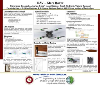
Astronaut Assistance Task
Tools must be collected by Rover and delivered to designated
astronaut drop zone. May be up to four drop zones at 1 km
away from start gate. UAV will deliver tools to minimize time
and thus maximize points for the task.
Task Requirements:
• Collect tools from Rover
• Carry four tools simultaneously
• Deliver within 1 meter radius of target
• Drop each tool individually
• Minimize total distance traveled
Tool Holders:
5.2 km Optimal Path
University Rover Challenge
Annual international competition at the Mars Desert Research
Station in Utah. The goal is to build a next generation system
that can eventually assist human exploration on Mars.
Competition Events:
• Astronaut Assistance Task
• Equipment Servicing Task
• Sample Return Task
• Terrain Traversal Task
System Overview
• Primary Weight: 11.1 kg
• Deadweight (URC required): 5.06 kg
• Total Weight: 16.16 kg
• Full Structure Length: 2.05 m
• Max Thrust: 480 N
• Max Flight Time w/ Deadweight: 31 min
• Max Flight Time w/o Deadweight: 58 min
Previous concept failed due to
inefficiency in placing tools in the
more concealed holders as well as
complexity in dropping each tool
individually.
Final design provides easy
loading access into two holder
variations. Holders are then
dropped individually utilizing
an E-Flite Servoless Payload
Release EFLA405.
Electronics
Video Transmission
• 2.4 Ghz HD Digital Video Downlink System
• Overall range: Approx. 1.7 km using omnidirectional antennas
• 2 cameras will be utilized
• One fixed for first person view (FPV) flight
• One attached to a 3 axis gyroscopic gimbal.
Commercial Flight Controller
• Naza Wookong M
• Stand alone Inertial Mass Unit and GPS System
• Position Accuracy - Vertical: ± 0.5m, Horizontal: ± 2m
Power Source
• 2 6S Tattu 22,000 mAh Batteries
• Batteries in series to bring total system voltage to 44.4 V
Propeller and Motor Testing
A thrust stand was constructed for
testing of various motor, propeller and
battery supply configurations.
• Moment arm between the center of
thrust and the pivot point is the same
as between the scale and the pivot
point
• Cnc’d delrin side brackets and
aluminum mounting brackets
Testing provided Thrust vs. Amps
curves for each configuration in order
to find optimum set up for UAV to lift
the heaviest payload while not
sacrificing flight time.
Tests Included:
• 4 bladed and 2 bladed configurations
using 22, 25 and 30 inch propellers
• 100 KV and 160 KV motors
• 22.2, 29.6, 37.0 and 44.4 V batteries
Structures
Main Components:
• Central Composite Truss Structure
• Four Unidirectional Carbon Fiber Arms
• Four 30-inch propellers
• Al 6061 Motor Mounts and Swivel Mounts
For analysis on the central truss structure, a 120 N remote force
was applied at the end of each arm and scoped to the swivel
mount connection point. This simulates the maximum thrust
produced by each 30 inch propeller and Turnigy Motor.
Total Deformation
The structure uses unidirectional intermediate modulus 7
(IM7), which has a yield strength of 3000 MPa. Use of
unidirectional allowed the fibers to be placed in the exact
orientation needed to increase the strength to weight ratio.
Von-Mises Stress
The molds for the composite pieces were CNC’d
out of starboard. The carbon fiber was laid
using the wet lay up process which entails
mixing and applying epoxy to the fibers and
using a vacuum to ensure the they conformed
to the right shape during the curing process.