SlideShare a Scribd company logo
1 of 2
Download to read offline
Successful inspections start with a plan and BeamTool makes it easy to model, validate and
document your plan. BeamTool is like CAD (Computer Aided Design) for the world of
ultrasonic inspection. This intuitive application allows users to easily design and simulate an
inspection and generate comprehensive documentation about their inspection plan. Start
by describing the piece to be inspected. Pieces can be described in 3 ways. Simple plate
piecesaredefinedbyenteringthelength,widthandthicknessofthepiece.ID/ODpiecesare
describedbyenteringtheODandtheIDorthethickness.Thecustompiecemodeallowsthe
user to use CAD style drawing tools to draft the subject. Once the piece has been described,
position a probe, adjust any beamset parameters to get the best coverage of the area of
interest, and visualize beam paths and coverage. Lastly generate a report documenting your
newtechnique.It'sthateasy!
BeamTool was designed to meet the modern operator's need for speed. Phased array
technique development is more complex than that for conventional ultrasonic inspection
and as such requires effective tools to help define the inspection approach. BeamTool's
innovative approach to phased array enables linear, sectorial and an informative reference
cursor optionto berepresented,helpingto clearlyconveyweldcoverage,HAZcoverageand
probe position, in addition to critical dimensions. The beamset parameters dialogue
displays a visual representation of the transducer elements that are used to form the
beamset. Beam spread visualization allows you to more accurately see your beamset
coverage for a specific dB drop, and near field visualization ensures that any focusing being
performed is within the near field. True Depth, Projection and Half Path focus types can be
visualized in your workspace and documented in your technique report.
Conventional probes can also be modeled in BeamTool with advanced support for beam
spreadandnearfieldrendering.
Time-Of-Flight Diffraction support provides tools to visualize and confirm zonal coverage.
TOFD techniques can be automatically annotated with cross-over dimensions and dead-
zonedepiction.EffortlesslydefineProbeCenterSeparation(PCS)byselectingthecross-over
depth you want and BeamTool automatically positions the probes to target your
requirements.
Techniques can be created using multiple probes and multiple disciplines within a single
workspace. Combine Phased Array with Conventional UT and TOFD probe configurations to
ensure complete coverage. Pitch-catch is a useful technique for viewing unfavourable weld
bevels or targeting geometry. Simply select P/C in the phased array configuration and the
BeamTool will solve and present the elements required; this feature can be set to reflect off
the weld bevel face accounting for return refraction. BeamTool makes it easy to develop
pitch-catch techniques for direct and indirect inspection using a single probe or a pair of
probes.
Use the bitmap drawing tool to add images to your drawings. Bitmaps can be imported and
scaled to be used as a backdrop or to use as a reference to trace over when drawing complex
specimens.
PhasedArray
ConventionalUT
TOFD
Multi-disciplineTechniqueDevelopmen
BitmapBackdrops
t
ESBEAMTOOL Modelling and Inspection Design for NDT
3-Dimensional Technique Visualization
Multi-Discipline Technique
IDOD TOFD Technique
Bitmap Backdrops
CADFunctionality
PieceConfiguration
WeldConfiguration
DefectSimulation
ConfigurableReporting
ZonalDiscrimination
Versatility
BeamToolintegratesapowerfulsetof CADtools thatmakesiteasyto drawcustompiecesto
develop a scan plan for your inspection. Users can draw geometries of any shape and size
and use the advanced ray-tracing to accurately ensure and document proper coverage. The
drawing tools have been greatly enhanced to make it even easier to draw and edit. Precision
coordinate and size readout, along with the ability to snap and a Command Prompt for
making complex specimen drawing precise, makes designing custom pieces fast and
easy.Multiplelayerscanbecreatedtoorganizeandfilteryourgeometries.
BeamTool provides native support for ID/OD type pieces common in pipeline and boilers.
The piece editor allows the piece to be easily defined using the OD and ID or thickness of a
part. Once the part is configured, phased array and conventional probes can be pinned to
the outside or inside of the part. As the user adjusts the probe location, the probe stays
pinnedtothepartandrevolvesaroundit.
Pick from a list of standard weld configurations or use the advanced weld configuration
editor to accurately create any weld profile you require. Weld cap geometries allow you to
clearlyillustratehowcloseyoucangetyourprobetoaweldwhileensuringpropercoverage.
Using the redline drawing system, you can draw defects onto a piece, then use two
dimensional ray-tracing to visualize beam reflections on these simulated defects. This is an
excellentvisualizationtoolforcommunicatingtechniqueobjectives.
HTML standards-based reporting allows reports to be generated and shared across the web
or email. Report content can be copied into other programs, such as Microsoft Word, and
edited for final presentation. Users can easily customize or create new reports containing
the information they need. The built-in HTML editor allows reports to be constructed in an
environment similar to a common word processor. Workspace fields can be dragged from a
fieldpickerintothetemplateforinclusioninthereport.
The BeamTool ZONAL Add-on provides the ability to define weld zones, which are used in
conjunction with a Zonal Beamset to provide automated targeting of individual phased
array beams into specific locations along the face of a weld bevel. The powerful new Beam
This versatile tool simplifies the technique design, validation and reporting process and is
adaptable for use by engineers, technicians, and auditors. If you are dealing with ultrasonic
inspections and require the ability to visualize and document the applications, BeamTool
willguideyouthroughtheprocessandproducetheprofessionalresultsindustrydemands.
SolverwillthenoptimizetheFocalLaw.
Complex Piece Geometry
Weld Configuration
Defect Simulation
Beam Solver
Eclipse Scientific
97 Randall Drive, Unit 2,
Waterloo, Ontario, Canada, N2V 1C5
+1 (519) 886-6717
sales
www.eclipsescientific.com
@eclipsescientific.com
Ask about the New BeamTool Add-On Modules
ES ES ESBEAMTOOL A-SCAN BEAMTOOL HIGHTEMP BEAMTOOL ZONAL

More Related Content

Similar to ESBeamTool_A4

Mi 291 chapter 3 (reverse engineering)(1)
Mi 291 chapter 3 (reverse engineering)(1)Mi 291 chapter 3 (reverse engineering)(1)
Mi 291 chapter 3 (reverse engineering)(1)varun teja G.V.V
 
Catia productenhancementoverview v5-6r2013
Catia productenhancementoverview v5-6r2013Catia productenhancementoverview v5-6r2013
Catia productenhancementoverview v5-6r2013Jimmy Chang
 
CAD CAM Lab MANNUAL Dr.BRAU.pdf
CAD CAM Lab MANNUAL Dr.BRAU.pdfCAD CAM Lab MANNUAL Dr.BRAU.pdf
CAD CAM Lab MANNUAL Dr.BRAU.pdfRameshPinninti2
 
Simpleware for Automotive Engineering
Simpleware for Automotive EngineeringSimpleware for Automotive Engineering
Simpleware for Automotive EngineeringSimpleware
 
Production Machining Article January 2009
Production Machining Article January 2009Production Machining Article January 2009
Production Machining Article January 2009Javier O. Vera
 
OS15 Brochure 2
OS15 Brochure 2OS15 Brochure 2
OS15 Brochure 2Brian Kemp
 
Learn about AutoCAD
Learn about AutoCADLearn about AutoCAD
Learn about AutoCADBahzad5
 
Outsourcing the Design & Manufacturing of Projection Engines for 3D Metrology...
Outsourcing the Design & Manufacturing of Projection Engines for 3D Metrology...Outsourcing the Design & Manufacturing of Projection Engines for 3D Metrology...
Outsourcing the Design & Manufacturing of Projection Engines for 3D Metrology...Giplink Digital
 
Efficient video compression using EZWT
Efficient video compression using EZWTEfficient video compression using EZWT
Efficient video compression using EZWTIJERA Editor
 
problems on Staad.pro and analysis of a 5 storey building using Etabs
problems on Staad.pro and analysis of a 5 storey building using Etabsproblems on Staad.pro and analysis of a 5 storey building using Etabs
problems on Staad.pro and analysis of a 5 storey building using Etabssrinivas cnu
 
CoreTechnologie launches universal 3D printing software with new features
CoreTechnologie launches universal 3D printing software with new featuresCoreTechnologie launches universal 3D printing software with new features
CoreTechnologie launches universal 3D printing software with new featuresKeen Ley
 
AUTO CAD ESSENTIALS EMERSON EDUARDO RODRIGUES
AUTO CAD ESSENTIALS EMERSON EDUARDO RODRIGUESAUTO CAD ESSENTIALS EMERSON EDUARDO RODRIGUES
AUTO CAD ESSENTIALS EMERSON EDUARDO RODRIGUESEMERSON EDUARDO RODRIGUES
 
AUTO CAD ESSENTIALS EMERSON EDUARDO RODRIGUES
AUTO CAD ESSENTIALS EMERSON EDUARDO RODRIGUESAUTO CAD ESSENTIALS EMERSON EDUARDO RODRIGUES
AUTO CAD ESSENTIALS EMERSON EDUARDO RODRIGUESEMERSON EDUARDO RODRIGUES
 
Basic knowledge AUTOCAD 📕-1.pdf
Basic knowledge AUTOCAD 📕-1.pdfBasic knowledge AUTOCAD 📕-1.pdf
Basic knowledge AUTOCAD 📕-1.pdfNiazKhan94
 
Autocad LT for Beginners Guide.pdf
Autocad LT for Beginners Guide.pdfAutocad LT for Beginners Guide.pdf
Autocad LT for Beginners Guide.pdfSridharMohanasundara
 

Similar to ESBeamTool_A4 (20)

Mi 291 chapter 3 (reverse engineering)(1)
Mi 291 chapter 3 (reverse engineering)(1)Mi 291 chapter 3 (reverse engineering)(1)
Mi 291 chapter 3 (reverse engineering)(1)
 
Catia productenhancementoverview v5-6r2013
Catia productenhancementoverview v5-6r2013Catia productenhancementoverview v5-6r2013
Catia productenhancementoverview v5-6r2013
 
Smart 3D
Smart 3DSmart 3D
Smart 3D
 
CAD CAM Lab MANNUAL Dr.BRAU.pdf
CAD CAM Lab MANNUAL Dr.BRAU.pdfCAD CAM Lab MANNUAL Dr.BRAU.pdf
CAD CAM Lab MANNUAL Dr.BRAU.pdf
 
Simpleware for Automotive Engineering
Simpleware for Automotive EngineeringSimpleware for Automotive Engineering
Simpleware for Automotive Engineering
 
Mobile CDS LTE Simulation Demo
Mobile CDS LTE Simulation Demo Mobile CDS LTE Simulation Demo
Mobile CDS LTE Simulation Demo
 
Production Machining Article January 2009
Production Machining Article January 2009Production Machining Article January 2009
Production Machining Article January 2009
 
OS15 Brochure 2
OS15 Brochure 2OS15 Brochure 2
OS15 Brochure 2
 
Learn about AutoCAD
Learn about AutoCADLearn about AutoCAD
Learn about AutoCAD
 
Outsourcing the Design & Manufacturing of Projection Engines for 3D Metrology...
Outsourcing the Design & Manufacturing of Projection Engines for 3D Metrology...Outsourcing the Design & Manufacturing of Projection Engines for 3D Metrology...
Outsourcing the Design & Manufacturing of Projection Engines for 3D Metrology...
 
Plant reverse engineering
Plant reverse engineeringPlant reverse engineering
Plant reverse engineering
 
dep_meshworks_brochure_2015
dep_meshworks_brochure_2015dep_meshworks_brochure_2015
dep_meshworks_brochure_2015
 
Efficient video compression using EZWT
Efficient video compression using EZWTEfficient video compression using EZWT
Efficient video compression using EZWT
 
problems on Staad.pro and analysis of a 5 storey building using Etabs
problems on Staad.pro and analysis of a 5 storey building using Etabsproblems on Staad.pro and analysis of a 5 storey building using Etabs
problems on Staad.pro and analysis of a 5 storey building using Etabs
 
CoreTechnologie launches universal 3D printing software with new features
CoreTechnologie launches universal 3D printing software with new featuresCoreTechnologie launches universal 3D printing software with new features
CoreTechnologie launches universal 3D printing software with new features
 
AUTO CAD ESSENTIALS EMERSON EDUARDO RODRIGUES
AUTO CAD ESSENTIALS EMERSON EDUARDO RODRIGUESAUTO CAD ESSENTIALS EMERSON EDUARDO RODRIGUES
AUTO CAD ESSENTIALS EMERSON EDUARDO RODRIGUES
 
AUTO CAD ESSENTIALS EMERSON EDUARDO RODRIGUES
AUTO CAD ESSENTIALS EMERSON EDUARDO RODRIGUESAUTO CAD ESSENTIALS EMERSON EDUARDO RODRIGUES
AUTO CAD ESSENTIALS EMERSON EDUARDO RODRIGUES
 
Basic knowledge AUTOCAD 📕-1.pdf
Basic knowledge AUTOCAD 📕-1.pdfBasic knowledge AUTOCAD 📕-1.pdf
Basic knowledge AUTOCAD 📕-1.pdf
 
Autocad LT for Beginners Guide.pdf
Autocad LT for Beginners Guide.pdfAutocad LT for Beginners Guide.pdf
Autocad LT for Beginners Guide.pdf
 
CAD notes.pdf
CAD notes.pdfCAD notes.pdf
CAD notes.pdf
 

More from Imaginos NDE

QMI 2014 Instrumentation Catalog
QMI 2014 Instrumentation CatalogQMI 2014 Instrumentation Catalog
QMI 2014 Instrumentation CatalogImaginos NDE
 
Airscan TX Brochure
Airscan TX BrochureAirscan TX Brochure
Airscan TX BrochureImaginos NDE
 
ESFlangeScanner_A4
ESFlangeScanner_A4ESFlangeScanner_A4
ESFlangeScanner_A4Imaginos NDE
 
ESInspectionBank_A4
ESInspectionBank_A4ESInspectionBank_A4
ESInspectionBank_A4Imaginos NDE
 
Flange Solution Suite_A4
Flange Solution Suite_A4Flange Solution Suite_A4
Flange Solution Suite_A4Imaginos NDE
 
OrthoDrive-brochure-A4 smaller
OrthoDrive-brochure-A4 smallerOrthoDrive-brochure-A4 smaller
OrthoDrive-brochure-A4 smallerImaginos NDE
 
OrthoMatic60-brochure-A4 smaller
OrthoMatic60-brochure-A4 smallerOrthoMatic60-brochure-A4 smaller
OrthoMatic60-brochure-A4 smallerImaginos NDE
 
PAUT-brochure-A4 smaller
PAUT-brochure-A4 smallerPAUT-brochure-A4 smaller
PAUT-brochure-A4 smallerImaginos NDE
 
PragmaPod-brochure-A4 smaller
PragmaPod-brochure-A4 smallerPragmaPod-brochure-A4 smaller
PragmaPod-brochure-A4 smallerImaginos NDE
 
PXIE-brochure-A4 smaller
PXIE-brochure-A4 smallerPXIE-brochure-A4 smaller
PXIE-brochure-A4 smallerImaginos NDE
 
PragmaLite-brochure-A4 smaller
PragmaLite-brochure-A4 smallerPragmaLite-brochure-A4 smaller
PragmaLite-brochure-A4 smallerImaginos NDE
 

More from Imaginos NDE (19)

3dii-brochure
3dii-brochure3dii-brochure
3dii-brochure
 
MII-900 plus
MII-900 plusMII-900 plus
MII-900 plus
 
MII-800XL_Plus
MII-800XL_PlusMII-800XL_Plus
MII-800XL_Plus
 
QMI 2014 Instrumentation Catalog
QMI 2014 Instrumentation CatalogQMI 2014 Instrumentation Catalog
QMI 2014 Instrumentation Catalog
 
Flyer_MC-DAQ
Flyer_MC-DAQFlyer_MC-DAQ
Flyer_MC-DAQ
 
Airscan TX Brochure
Airscan TX BrochureAirscan TX Brochure
Airscan TX Brochure
 
imperium-brochure
imperium-brochureimperium-brochure
imperium-brochure
 
ESBoltScanner_A4
ESBoltScanner_A4ESBoltScanner_A4
ESBoltScanner_A4
 
ESFlangeScanner_A4
ESFlangeScanner_A4ESFlangeScanner_A4
ESFlangeScanner_A4
 
ESInspectionBank_A4
ESInspectionBank_A4ESInspectionBank_A4
ESInspectionBank_A4
 
ESPipeBeetle_A4
ESPipeBeetle_A4ESPipeBeetle_A4
ESPipeBeetle_A4
 
ESTempMaster_A4
ESTempMaster_A4ESTempMaster_A4
ESTempMaster_A4
 
Flange Solution Suite_A4
Flange Solution Suite_A4Flange Solution Suite_A4
Flange Solution Suite_A4
 
OrthoDrive-brochure-A4 smaller
OrthoDrive-brochure-A4 smallerOrthoDrive-brochure-A4 smaller
OrthoDrive-brochure-A4 smaller
 
OrthoMatic60-brochure-A4 smaller
OrthoMatic60-brochure-A4 smallerOrthoMatic60-brochure-A4 smaller
OrthoMatic60-brochure-A4 smaller
 
PAUT-brochure-A4 smaller
PAUT-brochure-A4 smallerPAUT-brochure-A4 smaller
PAUT-brochure-A4 smaller
 
PragmaPod-brochure-A4 smaller
PragmaPod-brochure-A4 smallerPragmaPod-brochure-A4 smaller
PragmaPod-brochure-A4 smaller
 
PXIE-brochure-A4 smaller
PXIE-brochure-A4 smallerPXIE-brochure-A4 smaller
PXIE-brochure-A4 smaller
 
PragmaLite-brochure-A4 smaller
PragmaLite-brochure-A4 smallerPragmaLite-brochure-A4 smaller
PragmaLite-brochure-A4 smaller
 

ESBeamTool_A4

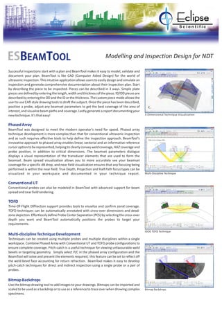
  • 1. Successful inspections start with a plan and BeamTool makes it easy to model, validate and document your plan. BeamTool is like CAD (Computer Aided Design) for the world of ultrasonic inspection. This intuitive application allows users to easily design and simulate an inspection and generate comprehensive documentation about their inspection plan. Start by describing the piece to be inspected. Pieces can be described in 3 ways. Simple plate piecesaredefinedbyenteringthelength,widthandthicknessofthepiece.ID/ODpiecesare describedbyenteringtheODandtheIDorthethickness.Thecustompiecemodeallowsthe user to use CAD style drawing tools to draft the subject. Once the piece has been described, position a probe, adjust any beamset parameters to get the best coverage of the area of interest, and visualize beam paths and coverage. Lastly generate a report documenting your newtechnique.It'sthateasy! BeamTool was designed to meet the modern operator's need for speed. Phased array technique development is more complex than that for conventional ultrasonic inspection and as such requires effective tools to help define the inspection approach. BeamTool's innovative approach to phased array enables linear, sectorial and an informative reference cursor optionto berepresented,helpingto clearlyconveyweldcoverage,HAZcoverageand probe position, in addition to critical dimensions. The beamset parameters dialogue displays a visual representation of the transducer elements that are used to form the beamset. Beam spread visualization allows you to more accurately see your beamset coverage for a specific dB drop, and near field visualization ensures that any focusing being performed is within the near field. True Depth, Projection and Half Path focus types can be visualized in your workspace and documented in your technique report. Conventional probes can also be modeled in BeamTool with advanced support for beam spreadandnearfieldrendering. Time-Of-Flight Diffraction support provides tools to visualize and confirm zonal coverage. TOFD techniques can be automatically annotated with cross-over dimensions and dead- zonedepiction.EffortlesslydefineProbeCenterSeparation(PCS)byselectingthecross-over depth you want and BeamTool automatically positions the probes to target your requirements. Techniques can be created using multiple probes and multiple disciplines within a single workspace. Combine Phased Array with Conventional UT and TOFD probe configurations to ensure complete coverage. Pitch-catch is a useful technique for viewing unfavourable weld bevels or targeting geometry. Simply select P/C in the phased array configuration and the BeamTool will solve and present the elements required; this feature can be set to reflect off the weld bevel face accounting for return refraction. BeamTool makes it easy to develop pitch-catch techniques for direct and indirect inspection using a single probe or a pair of probes. Use the bitmap drawing tool to add images to your drawings. Bitmaps can be imported and scaled to be used as a backdrop or to use as a reference to trace over when drawing complex specimens. PhasedArray ConventionalUT TOFD Multi-disciplineTechniqueDevelopmen BitmapBackdrops t ESBEAMTOOL Modelling and Inspection Design for NDT 3-Dimensional Technique Visualization Multi-Discipline Technique IDOD TOFD Technique Bitmap Backdrops
  • 2. CADFunctionality PieceConfiguration WeldConfiguration DefectSimulation ConfigurableReporting ZonalDiscrimination Versatility BeamToolintegratesapowerfulsetof CADtools thatmakesiteasyto drawcustompiecesto develop a scan plan for your inspection. Users can draw geometries of any shape and size and use the advanced ray-tracing to accurately ensure and document proper coverage. The drawing tools have been greatly enhanced to make it even easier to draw and edit. Precision coordinate and size readout, along with the ability to snap and a Command Prompt for making complex specimen drawing precise, makes designing custom pieces fast and easy.Multiplelayerscanbecreatedtoorganizeandfilteryourgeometries. BeamTool provides native support for ID/OD type pieces common in pipeline and boilers. The piece editor allows the piece to be easily defined using the OD and ID or thickness of a part. Once the part is configured, phased array and conventional probes can be pinned to the outside or inside of the part. As the user adjusts the probe location, the probe stays pinnedtothepartandrevolvesaroundit. Pick from a list of standard weld configurations or use the advanced weld configuration editor to accurately create any weld profile you require. Weld cap geometries allow you to clearlyillustratehowcloseyoucangetyourprobetoaweldwhileensuringpropercoverage. Using the redline drawing system, you can draw defects onto a piece, then use two dimensional ray-tracing to visualize beam reflections on these simulated defects. This is an excellentvisualizationtoolforcommunicatingtechniqueobjectives. HTML standards-based reporting allows reports to be generated and shared across the web or email. Report content can be copied into other programs, such as Microsoft Word, and edited for final presentation. Users can easily customize or create new reports containing the information they need. The built-in HTML editor allows reports to be constructed in an environment similar to a common word processor. Workspace fields can be dragged from a fieldpickerintothetemplateforinclusioninthereport. The BeamTool ZONAL Add-on provides the ability to define weld zones, which are used in conjunction with a Zonal Beamset to provide automated targeting of individual phased array beams into specific locations along the face of a weld bevel. The powerful new Beam This versatile tool simplifies the technique design, validation and reporting process and is adaptable for use by engineers, technicians, and auditors. If you are dealing with ultrasonic inspections and require the ability to visualize and document the applications, BeamTool willguideyouthroughtheprocessandproducetheprofessionalresultsindustrydemands. SolverwillthenoptimizetheFocalLaw. Complex Piece Geometry Weld Configuration Defect Simulation Beam Solver Eclipse Scientific 97 Randall Drive, Unit 2, Waterloo, Ontario, Canada, N2V 1C5 +1 (519) 886-6717 sales www.eclipsescientific.com @eclipsescientific.com Ask about the New BeamTool Add-On Modules ES ES ESBEAMTOOL A-SCAN BEAMTOOL HIGHTEMP BEAMTOOL ZONAL