

Recommended
Recommended
More Related Content
What's hot
What's hot (20)
Viewers also liked
Viewers also liked (20)
Similar to J012256367
Similar to J012256367 (20)
More from IOSR Journals
Recently uploaded
Recently uploaded (20)
J012256367
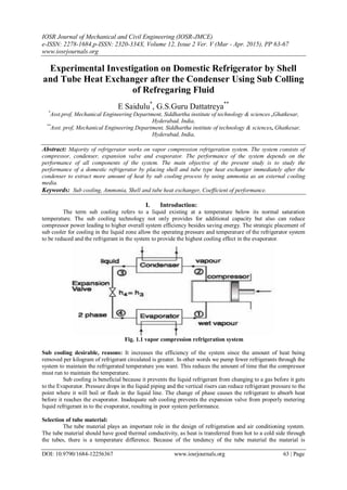
- 1. IOSR Journal of Mechanical and Civil Engineering (IOSR-JMCE) e-ISSN: 2278-1684,p-ISSN: 2320-334X, Volume 12, Issue 2 Ver. V (Mar - Apr. 2015), PP 63-67 www.iosrjournals.org DOI: 10.9790/1684-12256367 www.iosrjournals.org 63 | Page Experimental Investigation on Domestic Refrigerator by Shell and Tube Heat Exchanger after the Condenser Using Sub Colling of Refregaring Fluid E Saidulu* , G.S.Guru Dattatreya** * Asst.prof, Mechanical Engineering Department, Siddhartha institute of technology & sciences ,Ghatkesar, Hyderabad, India, ** Asst. prof, Mechanical Engineering Department, Siddhartha institute of technology & sciences, Ghatkesar, Hyderabad, India, Abstract: Majority of refrigerator works on vapor compression refrigeration system. The system consists of compressor, condenser, expansion valve and evaporator. The performance of the system depends on the performance of all components of the system. The main objective of the present study is to study the performance of a domestic refrigerator by placing shell and tube type heat exchanger immediately after the condenser to extract more amount of heat by sub cooling process by using ammonia as an external cooling media. Keywords: Sub cooling, Ammonia, Shell and tube heat exchanger, Coefficient of performance. I. Introduction: The term sub cooling refers to a liquid existing at a temperature below its normal saturation temperature. The sub cooling technology not only provides for additional capacity but also can reduce compressor power leading to higher overall system efficiency besides saving energy. The strategic placement of sub cooler for cooling in the liquid zone allow the operating pressure and temperature of the refrigerator system to be reduced and the refrigerant in the system to provide the highest cooling effect in the evaporator. Fig. 1.1 vapor compression refrigeration system Sub cooling desirable, reasons: It increases the efficiency of the system since the amount of heat being removed per kilogram of refrigerant circulated is greater. In other words we pump fewer refrigerants through the system to maintain the refrigerated temperature you want. This reduces the amount of time that the compressor must run to maintain the temperature. Sub cooling is beneficial because it prevents the liquid refrigerant from changing to a gas before it gets to the Evaporator. Pressure drops in the liquid piping and the vertical risers can reduce refrigerant pressure to the point where it will boil or flash in the liquid line. The change of phase causes the refrigerant to absorb heat before it reaches the evaporator. Inadequate sub cooling prevents the expansion valve from properly metering liquid refrigerant in to the evaporator, resulting in poor system performance. Selection of tube material: The tube material plays an important role in the design of refrigeration and air conditioning system. The tube material should have good thermal conductivity, as heat is transferred from hot to a cold side through the tubes, there is a temperature difference. Because of the tendency of the tube material the material is
- 2. Experimental Investigation on Domestic Refrigerator by Shell and Tube Heat Exchanger after … DOI: 10.9790/1684-12256367 www.iosrjournals.org 64 | Page thermally expands differently at various temperatures, and also thermal stresses will also occur during operation. All of these requirements call for careful selection of strong, thermally conductive, corrosion resistant, high quality tube material, typically metals including copper alloy, stainless steel, galvanized iron, carbon steel, nickel etc. Poor choice of tube material could result in a leak through the tube between shell and tube sides causing fluid cross-contamination and possibly loss of pressure. Fig.1.2: Shell and tube heat exchanger Shell and tube heat exchanger: A shell and tube heat exchanger is a class of heat exchanger designs. It is the most common type of heat exchanger and is suited for high pressure applications. As its name implies, this type of the heat exchanger consists of a shell with bundle of tubes inside it. One fluid runs through the tubes, another fluid flows over the tubes to transfer heat between the two fluids. The set of tubes is called tube bundle, and may be composed of Several types of tubes. 107.80 Properties of ammonia: Molecular formula NH3 Molar mass 17.031 g/mol Appearance Colorless gas Odour strong pungent odour Density 0.86 kg/m3 (1.013 bar ) Melting point −77.73 °C Boiling point −33.34 °C Solubility in water 47% (0 °C) Solubility soluble in chloroform, ether, ethanol, methanol Structure: Molecular formula NH3 Molar mass 17.031 g/mol Appearance Colorless gas Odour strong pungent odour Density 0.86 kg/m3 (1.013 bar ) Melting point −77.73 °C Boiling point −33.34 °C Solubility in water 47% (0 °C) Solubility soluble in chloroform, ether, ethanol, methanol Structure Molecular shape Trigonal pyramid Thermo chemistry Flash point flammable gas (see text) Explosive limits 15–28% 101.7 Pm
- 3. Experimental Investigation on Domestic Refrigerator by Shell and Tube Heat Exchanger after … DOI: 10.9790/1684-12256367 www.iosrjournals.org 65 | Page Ammonia, or azane, is a compound of nitrogen and hydrogen with the formulae NH3. It is a colorless gas with a characteristic pungent smell. NH3 boils at −33.34 °C (−28.012 °F) at a pressure of one atmosphere, so the liquid must be stored under pressure or at low temperature. Household ammonia or ammonium hydroxide is a solution of NH3 in water. Measured in units of the Baumé scale (density), with 26 degrees baumé (about 30% (by weight) ammonia at 15.5 °C or 59.9 °F) being the typical high-concentration commercial product. Solvent properties: Ammonia is miscible with water. In an aqueous solution, it can be expelled by boiling. The aqueous solution of ammonia is basic. The maximum concentration of ammonia in water (a saturated solution) has a density of 0.880 g/cm3 and is often known as '.880 ammonia'. Ammonia does not burn readily or sustain combustion, except under narrow fuel-to-air mixtures of 15–25% air. One of the most characteristic properties of ammonia is its basicity. II. Experimental Setup The experimental test rig has a vapor refrigeration cycle working with refrigerant R-134a it consists of a compressor, evaporator, air cooled condenser, receiver, expansion valve and two shell and tube heat exchangers, One placed after condenser and the other after the evaporator. In the present work on the domestic refrigerator placing of shell and tube heat exchanger after the condenser contains ammonia that absorbs the heat from the refrigerating fluid coming from condenser. Sub cooling will occur and allow the operating pressure and temperature to be lowered. The net refrigeration effect and overall performance of the system will increase. The ammonia that is present in the modified shell and tube heat exchanger is converted from liquid to vapor state. The vaporized ammonia exchanges heat with the refrigerant coming out from the heat exchanger placed immediately after the evaporator is converted in to liquid .The cooled ammonia returns back to shell and tube heat exchanger after the condenser. Modifications made to the existing system Heat exchanger (HE-1) placed after the expansion valve in which liquid ammonia converts to vapor ammonia. Heat exchanger (HE-2) placed after the evaporator in which vapour ammonia converts to liquid. The ammonia continuously transferred from HE-1 to HE-2 and vice-versa. Fig 1.3: Proposed System Fig 1.4: Shell and Tube Heat Exchanger
- 4. Experimental Investigation on Domestic Refrigerator by Shell and Tube Heat Exchanger after … DOI: 10.9790/1684-12256367 www.iosrjournals.org 66 | Page In the above fig.1.4 the liquid - vapor phase refrigerant flows through the tube and the Ammonia flows outside the tubes but inside the shell (the shell side). Heat is transferred from refrigerant to Ammonia through the tube walls, either from tube side to shell or vice versa III. Tabular Column: Performance with Suctionpressure (bar) Discharge pressure(bar) Temperatureof vapour refrigerantbefore shells(0C) Inlettemperature of compressor(0C) Outlet temperatureof compressor(0C) Condenseroutlet temperature beforeshell SS0shell(0C ((()S(((shell(0C)Condenseroutlet temperatureafter shell(0C)() Evaporator temperature(0C) Coefficientof performance Base line 0.9 18.0 - 19.1 78.2 - 42.9 2.6 5.16 Ammonia 0.6 11.0 18.1 25.0 69.5 42.0 39.5 1.7 6.11 Graph 1 Comparison of Heat Rejection Rate for Existing System and Proposed System Graph 2 Comparison of net refrigeration effect for existing system and proposed system Graph 3 Comparison of power input per tone of refrigeration for existing system and proposed system
- 5. Experimental Investigation on Domestic Refrigerator by Shell and Tube Heat Exchanger after … DOI: 10.9790/1684-12256367 www.iosrjournals.org 67 | Page Graph 4 Comparison of coefficient of performance for existing system and proposed system IV. Result And Discussions: By placing shell and tube heat exchanger after condenser the refrigerant is sub cooled by 2.5 0C when ammonia is used as coolant. Due to sub cooling the net refrigeration effect is increased and the C.O.P of the system is increased. The increase in coefficient of performance is 18.4% when ammonia is used as coolant. Coefficient of performance of refrigerator will be more with ammonia when compared with existing system References: [1]. Akintunde, M.A. 2004b. Experimental Investigation of The performance of Vapor Compression Refrigeration Systems. Federal University of Technology, Akure, Nigeria. [2]. Eckert, E.R.G.; Goldstein, R.J.; Ibele, W.E.; Patankar, S.V.; Simon, T.W.; Strykowski, P.J.; Tamma, K.K.; Kuehn, T.H.; Bar- Cohen, A.; Heberlein, J.V.R.; (Sep 1997), Heat transfer- a review of 1994 literature, International Journal of Heat and Mass Transfer 40-16, 3729-3804. [3]. Performance enhancement of a household refrigerator by addition of latent heat storage International Journal of Refrigeration, Volume 31, Issue 5, August 2008, Pages 892-901 Azzouz, K.; Leducq, D.; Gobin, D. [4]. Akintunde, M.A. 2004b. Experimental Investigation of The performance of Vapor Compression Refrigeration Systems. Federal University of Technology, Akure, Nigeria. [5]. Kays WM, London AL. Compact heat exchangers. New- York: McGraw-Hill, 1984. [6]. Seshimo Y, Fujii M. An experimental study of the performance of plate fin and tube heat exchangers at lowReynolds numbers. ASME/JSME Thermal Engineering Proceedings, ASME 1991;4:449–54. [7]. James R. lines . ly Coiled Heat Exchangers offer Advantages GRAHAM MANUFACTURI