
Recommended
Recommended
More Related Content
Similar to DOC-20231017-WA0003..pptx
Similar to DOC-20231017-WA0003..pptx (20)
Recently uploaded
Recently uploaded (20)
DOC-20231017-WA0003..pptx
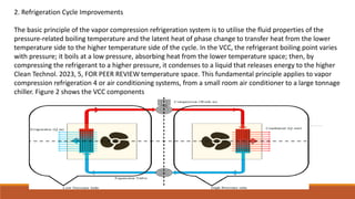
- 1. 2. Refrigeration Cycle Improvements The basic principle of the vapor compression refrigeration system is to utilise the fluid properties of the pressure-related boiling temperature and the latent heat of phase change to transfer heat from the lower temperature side to the higher temperature side of the cycle. In the VCC, the refrigerant boiling point varies with pressure; it boils at a low pressure, absorbing heat from the lower temperature space; then, by compressing the refrigerant to a higher pressure, it condenses to a liquid that releases energy to the higher Clean Technol. 2023, 5, FOR PEER REVIEW temperature space. This fundamental principle applies to vapor compression refrigeration 4 or air conditioning systems, from a small room air conditioner to a large tonnage chiller. Figure 2 shows the VCC components
- 2. Cycle Improvement by Increasing Sub-Cooling and Superheating sub-cooling could be identified as decreasing the refrigerant temperature below its condensing temperature at a specific pressure. On the other hand, superheating increases the refrigerant temperature above the boiling temperature at a specific pressure. Figure shows the effect of superheating and sub-cooling on the cycle capacity and the system COP Sub- cooling is commonly increased in three main ways: Suction Line Heat Exchanger (SI HX) Mechanical Sub-cooling (MS) Thermoelectric Sub-cooling (TS) The compressor technologies are many and evolving but can be classified into three main types: 1. Positive displacement, such as reciprocating and linear compressors 2. Rotary, including scroll, screw, root, and rolling compressors 3. Kinematic compressors, such as centrifugal and axial compressors
- 3. Suction Line Heat Exchanger (SLHX) The suction line heat exchanger is used to exchange heat between the expansion device inlet (sub-cooling) and the compressor inlet (superheating) to improve the system efficiency by increasing the evaporator capacity. Mechanical Sub-Cooling (MS) Mechanical sub-cooling aims to improve the cooling capacity using a small mechanical cooling system. As shown in Figure 5, the secondary cooling system cools down the refrigerant prior to the expansion stage to enhance the system’s efficiency.
- 4. Thermoelectric Sub-Cooling (TS) A thermoelectric system is a device that works on the Peltier effect and can convert electricity directly to the temperature difference without any moving parts, which makes it extremely reliable. However, its application is very limited due to its relatively low energy efficiency, especially when used with high- temperature lifts. Figure 6 shows a schematic diagram of a vapor compression cycle with thermoelectric internal heat exchanger.
- 5. Cycle Improvement by Expansion Loses Recovery In the refrigeration cycle, various expansion devices, including capillary tubes, orifices, thermostatic expansion valves, or electronic expansion valves, are commonly used to expand the refrigerant to lower its pressure. Theoretically, this process should be isenthalpic, meaning enthalpy should be reserved. However, in reality, the expansion process wastes energy that can be recovered by using expanders or ejectors. The Expander Cycle The expander is a small device that is similar to the compressor principle in reverse. It is used to expand the refrigerant and convert the recovered energy of the expansion process into kinetic energy that can be used for different purposes; one of these purposes is to improve the system COP and the cooling capacity
- 6. Ejector Cycle The ejector consists of a mixing chamber, nozzle, and diffuser. The ejector’s main function is to mix refrigerant from the high-pressure side with the refrigerant from the low-pressure side. When the refrigerant flows from the condenser through the ejector and past the nozzle, the pressure drops, and it draws the refrigerant from the evaporator outlet; both the low and the high-pressure streams mix in the mixing chamber, and the diffuser recovers the energy of the mixed fluid.
- 7. Refrigerants Development and Environmental Assessment Refrigerants are used to absorb and transfer heat between space and the surrounding environment, mainly through vapor compression-based equipment. The initial stage started with the invention of VCC systems and lasted until the late 1920s, when mainly natural materials such as ammonia, carbon dioxide, hydrocarbons, sulphur dioxide, chloroethene, air, ether, and methyl chloride were used as refrigerants. Then, with the invention of freon in 1930 In order to reduce the environmental impact of refrigerants, some restrictions on the use of HCFCs, also known as freons, were suggested due to their GWP
- 8. NATURAL REFRIGERANTS AIR: Air offers many advantages as a refrigerant, such as safety, availability, and being environmentally friendly Air-based refrigeration systems work on the Joule or reverse Brayton cycle, by which air is heated and cooled via compression and expansion With the development of compressors, expanders, and compact heat exchangers, air-based cooling systems are becoming more efficient and are comparable to conventional refrigerants.
- 9. Water has some attractive properties as it is environmentally friendly with an ODP of 0 and a GWP of less than 1, which is rare for refrigerants Despite all these advantages, using water as a refrigerant requires working with ex-tremely low operating pressures, which adds challenges in terms of the large specificvolume of water vapor, which requires a high volumetric flow rate and, thus, largecompressors [71]. Hydrocarbons consist of pure hydrogen compounds and are considered a viable op- tion for refrigeration due to their suitability for cooling, low environmental impact, and energy efficiency.
- 10. Ammonia (NH3) has been used in refrigeration since 1872[7] . Ammonia has attractedpopularity due to its thermodynamic properties, including efficiency, availability, low cost,and low environmental impact. Moreover, it does not cause any health effects unless the exposure continues for more than 30 min. Furthermore, ammonia is classified as an A2L low-flammability refrigerant by ASHRAE.
- 11. Co2 ( Carbondioxide) Carbon dioxide is considered one of the most promising natural refrigerants due to its safety and environmental advantages. The EPA classifies it as an Al refrigerant, which defines the least hazardous and toxic category. In order to extract the system COP, different operating pressures and sub-cooling conditions were tested. The study concluded that the optimum ambient temperatures were 25 deg * C, 30.4 deg * C and 35.1 deg * C and 1 - 15.6 deg * C to - 4.1 deg * Cevaporation temperature.
- 12. Advantages Disadvantages Applications 1.AIR ( Brayton cycle) Applications: Airplane cabin air-conditioning Advantages: Safety, availability, environmentally stable Disadvantages: Relatively low cycle efficiency 2.WATER: ( carnot cycle) Applications: Absorption Chillers, Evaporative Cooling Heat Pumps Advantages: Safety Availability Environmentally Stable Disadvantages: High Boiling Temperature Corrosive High Specific Volume
- 13. 3. HYDROCARBONS ( carnot) Applications: small charge refrigeration ,truck refrigeration. Advantages: suitable thermodynamic properties,low volume Disadvantages: Extremely flammable 4.Co2 ( carnot) Applications : Cascade refrigeration Advantages: Low cost Disadvantage: High pressure condense system is needed
- 14. 5.Ammonia (carnot) Advantage : Low environmental impact Disadvantage: Toxic at high concentration Application: Absorption chillers
- 15. ASSESSMENT FOR REFRIGERANTS Refrigerant Water Ammonia Carbon Dioxide Isobutane Propane Tetrafluoroethan e Code R-718 R-717 R-744 R-600a R-290 R-134a ODP 0 0 0 0 0 0 GWP (100 Years) <1 <1 1 <5 20 1430 Critical temperature (◦C) 373.9 132.2 31 134.7 96.7 101.06 Critical pressure (kPa) 22.06 11.33 7.38 3.629 4.25 4.059 Normal boiling temperature (◦C) 100 −33 −78.4 −11.7 −42.2 −26.074 Freezing temperature (◦C) 0 −77.7 −56.55 −159.6 −188 −103.3 Latent heat of vaporization at 20 ◦ C (kJ/kg) 2453.8 1187.2 155.2 367 344.3 180 Safety Classification A1 B2 A1 A3 A3 A1