
![Design of Type-III Control Loops using Explicit Analytical PID Tuning technique
DOI: 10.9790/1676-10313342 www.iosrjournals.org 34 | Page
Of course, these two aforementioned requirements are practically impossible to be satisfied at the same
time in real-world plants and applications, since the existence of disturbances d(t) alters the behavior of the
process during its operation. In real-world problems, disturbances d(t) are classified into two categories. The
first category involves disturbances coming from the process itself, known as internal disturbances. The second
category includes any external or exogenous disturbance that can be relevant basically to the environmental
conditions the process is located at, i.e., varying loads acting as input signals to the output of the process, noise
coming from the measuring equipment, etc. With respect to the above, it is without any doubt apparent that
during the plants operation, perfect tracking of the output y(t) for repetitive and different input signals u(t) can
only be satisfied if fast suppression of internal and external disturbances is achieved.
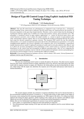
1.2 Closed loop control system
In this section, we refer to the closed-loop control system presented in Fig.2 where G(s), C(s) stand for
the process and the controller transfer functions, respectively. Output of the control loop is defined as y(s) and
kh stands for the feedback path for the output y(s). Signal r (s) is the reference input to the control loop, do(s)
and di(s) are the output and input disturbance signals, respectively, and nr(s), no(s) are the noise signals at the
reference input and the process output, respectively. Finally, kp stands for the plant's dc gain at steady state.
Fig 2 Closed loop control system
G(s) is the plant transfer function, C(s) is the controller transfer function, r(s) is the reference signal,
y(s) is the output of the control loop, yf (s) is the output signal after kh, do(s) and di(s) are the output and input
disturbance signals, respectively, and nr(s) and no(s) are the noise signals at the reference input and process
output, respectively. kp stands for the plants dc gain, and kh is the feedback path.
1.3 Type of control loop
Preliminary definitions regarding the type of control loop are given in this section. The error e(s) is defined as
( ) ( ) ( )
( ) ( )[1 ( )]
( ) ( ) ( )
( )
( )
( )
e s r s y s
e s r s T s
e s r s S s
y s
T s
r s
(1)
Where r(s) = Reference input signal
y(s) = output signal
When all other inputs are considered to be zero
1 1
1 1 0
1 1
1 1 0
..........
( ) ( )
..........
m m
m m
n n
n m
b s b s b s b
T s r s
a s a s a s a
(2)
1
1 0
1 1
1 1 0
........ .........
( ) ( )
..........
n m
n m
n n
n m
a s c s c s c
e s r s
a s a s a s a
(3)](data:image/gif;base64,R0lGODlhAQABAIAAAAAAAP///yH5BAEAAAAALAAAAAABAAEAAAIBRAA7)
Recommended
Recommended
More Related Content
What's hot
Viewers also liked
Viewers also liked (20)
Similar to F010313342
Similar to F010313342 (20)
More from IOSR Journals
Recently uploaded
Recently uploaded (20)
F010313342
- 1. IOSR Journal of Electrical and Electronics Engineering (IOSR-JEEE) e-ISSN: 2278-1676,p-ISSN: 2320-3331, Volume 10, Issue 3 Ver. I (May – Jun. 2015), PP 33-42 www.iosrjournals.org DOI: 10.9790/1676-10313342 www.iosrjournals.org 33 | Page Design of Type-III Control Loops Using Explicit Analytical PID Tuning Technique A.H.Munde 1 , S.S.Sankeshwari 2 1,2. (P.G.Department, M.B.E.S.C.O.E Ambajogai./ Dr.B.A.M.University, INDIA ) Abstract : The type III control loops are advantageous as compared to type I and type II as , if frequency domain modeling of the control loop is followed, type-III control loops are characterized by the presence of three pure integrators in the open-loop transfer function. Therefore, such a control scheme has the advantage of tracking fast reference signals since it exhibits zero steady-state position, velocity, and acceleration error. This advantage is considered critical in many industry applications, i.e., control of electrical motor drives and control of power converters, since it allows the output variable, i.e., current or speed, to track perfectly step, ramp, and parabolic reference signals. Here we are investigating the problem of designing PID type III control loop using the Revised symmetrical optimum criterion. The proposed PID control law has the following characteristics: 1) it consists of analytical expressions that involve all modeled process parameters; 2) it can be straightforwardly applied to any process regardless of its complexity since, for its development, a generalized transfer function process model is employed consisting of n poles and m zeros plus unknown time delay d; and 3) it allows for accurate investigation of the performance of the control action to exogenous and internal disturbances in the control loop and investigation of different operating points. Here we are comparing the conventional symmetrical optimum criterion with the revised symmetrical optimum criterion and justifying how the proposed control technique is best by considering three different examples. Keywords- Conventional Symmetrical optimum criterion, control schemes, PID control, Revised Symmetrical optimum criterion, type III control loop. I. Introduction 1.1 Definitions and Preliminaries The core of a closed-loop control system is namely the plant or the process. The plant receives signals from the outer world, commonly known as inputs, depicted by u(t) in Fig, and acts at the same time to the outer world with its response, known as output, y(t). Moreover, the whole process can also be described by its states x(t), which along with the inputs u(t), determine the response y(t) of the plant itself process itself, known as internal disturbances. Fig 1 Controlled process The second category includes any external or exogenous disturbance that can be relevant basically to the environmental conditions the process is located at, i.e., varying loads acting as input signals to the output of the process, noise coming from the measuring equipment, etc. With respect to the above, it is without any doubt apparent that during the plants operation, perfect tracking of the output y(t) for repetitive and different input signals u(t) can only be satisfied if fast suppression of internal and external disturbances is achieved. Ideally, there are two fundamental requirements of a process in any real time application: 1. From a plant, it is required that its output y(t) must track perfectly its input u(t). 2. The aforementioned output tracking of the input u(t) must also be repetitive and for several deferent input signals u(t).
- 2. Design of Type-III Control Loops using Explicit Analytical PID Tuning technique DOI: 10.9790/1676-10313342 www.iosrjournals.org 34 | Page Of course, these two aforementioned requirements are practically impossible to be satisfied at the same time in real-world plants and applications, since the existence of disturbances d(t) alters the behavior of the process during its operation. In real-world problems, disturbances d(t) are classified into two categories. The first category involves disturbances coming from the process itself, known as internal disturbances. The second category includes any external or exogenous disturbance that can be relevant basically to the environmental conditions the process is located at, i.e., varying loads acting as input signals to the output of the process, noise coming from the measuring equipment, etc. With respect to the above, it is without any doubt apparent that during the plants operation, perfect tracking of the output y(t) for repetitive and different input signals u(t) can only be satisfied if fast suppression of internal and external disturbances is achieved. 1.2 Closed loop control system In this section, we refer to the closed-loop control system presented in Fig.2 where G(s), C(s) stand for the process and the controller transfer functions, respectively. Output of the control loop is defined as y(s) and kh stands for the feedback path for the output y(s). Signal r (s) is the reference input to the control loop, do(s) and di(s) are the output and input disturbance signals, respectively, and nr(s), no(s) are the noise signals at the reference input and the process output, respectively. Finally, kp stands for the plant's dc gain at steady state. Fig 2 Closed loop control system G(s) is the plant transfer function, C(s) is the controller transfer function, r(s) is the reference signal, y(s) is the output of the control loop, yf (s) is the output signal after kh, do(s) and di(s) are the output and input disturbance signals, respectively, and nr(s) and no(s) are the noise signals at the reference input and process output, respectively. kp stands for the plants dc gain, and kh is the feedback path. 1.3 Type of control loop Preliminary definitions regarding the type of control loop are given in this section. The error e(s) is defined as ( ) ( ) ( ) ( ) ( )[1 ( )] ( ) ( ) ( ) ( ) ( ) ( ) e s r s y s e s r s T s e s r s S s y s T s r s (1) Where r(s) = Reference input signal y(s) = output signal When all other inputs are considered to be zero 1 1 1 1 0 1 1 1 1 0 .......... ( ) ( ) .......... m m m m n n n m b s b s b s b T s r s a s a s a s a (2) 1 1 0 1 1 1 1 0 ........ ......... ( ) ( ) .......... n m n m n n n m a s c s c s c e s r s a s a s a s a (3)
- 3. Design of Type-III Control Loops using Explicit Analytical PID Tuning technique DOI: 10.9790/1676-10313342 www.iosrjournals.org 35 | Page Where j j jc a b According to the final value theorem, e(s) is stable whenever ( )e is equal to 2 1 2 1 0 1 1 1 1 0 ........ ( ) lim ( ) .......... n n n ns n m a s c s c s c e s r s a s a s a s a (4) 1.3.1 Type 1 control loop If 1 ( )r s s then 0 0 ( ) lim ( ) 0 s c e a e (5) At 0 0c or 0 0a b 1.3.2 Type 2 control loop If 2 1 ( )r s s then 1 1 1 0 0 ( ) lim lim ( ) 0 s s c a b e a a e (6) At 1 0c or 1 1a b 1.3.3 Type 3 control loop If 3 1 ( )r s s then 2 2 2 0 0 ( ) lim lim ( ) 0 s s c a b e a a e (7) At 2 0c or 2 2a b 1 1 1 1 0 1 1 1 1 0 .......... ( ) ( ) .......... m m m m n n n m b s b s b s b T s r s a s a s a s a (8) 2 3 2 3 2 1 1 2 2 1 1 1 1 0 ...... .......... ( ) .......... n n m m n n m m n n n m a s a s b s b s a b S s s a s a s a s a (9) II. Conventional Symmetrical Optimum Design Criterion In this section, the conventional PID tuning via the symmetrical optimum criterion is presented. The closed-loop system of Fig.2 is considered again, where r(s), e(s), u(s), y(s), do(s), and di(s) are the reference input, the control error, the input and output of the plant, and the output and input disturbances, respectively. An integrating process met in many real-world applications can be defined by 1 1 ) (1 )(1 )pm p G s sT sT sT (10)
- 4. Design of Type-III Control Loops using Explicit Analytical PID Tuning technique DOI: 10.9790/1676-10313342 www.iosrjournals.org 36 | Page Where Tm is the integrator‟s plant time constant, Tp1 is the plant‟s dominant time constant, and TΣp is the plant‟s unmodeled dynamics. Supposing that the dominant time constant Tp1 is evaluated, the proposed controller is defined by 1 2 2 (1 )(1 )(1 ) ( ) (1 )(1 )C C n v x i sT sT sT C s s T sT sT (11) 2 4 3 2 ( ) ( ) ( ) p n v p n v p i m i m p h n v p h n v p h s k T T sk T T k T s TT T s TT s s k k T T sk k T T k k (12) 2 2 2 2 2 2 4 2 2 2 2 2 (1 ) ( ) | ( ) | [ (1 )] [( ( ) )] p n v p n v i m p h n v p h n v i m k T T k T T T j TT T k k T T k k T T TT (13) 2 8 6 2 2 4 2 2 2 2 2 ( ) ( 2 ) [2 2( ) ( ) ] ( ) ( ) ( ) i m i m i m p h n v p h i m n v i m p h i m p h n v p h TT T TT TT k k T T T k k TT T T T TT D k k T T k k T T k k (14) Where TΣc1, TΣc2 are known and sufficiently small time constants compared to Tp1, arising from the controller‟s implementation. By setting Tx = Tp1 (pole–zero cancellation) and assuming that TΣc = TΣc1+ TΣc2 and TΣc1 TΣc2 ≈ 0, the transfer function of the closed-loop control system is equal to (12), shown at the bottom of the next page, where TΣ = TΣc + TΣp . The magnitude of (12) is given by (13), shown at the bottom of the next page. The denominator of (13) is defined by (14), shown at the bottom of the next page. One way to optimize the magnitude of (13) is to set the terms of ωj , j = 2, 4, 6, . . ., in (14) equal to zero, starting again from the lower frequency range [17]. Setting kh = 1 and the term of ω6 equal to zero leads to 2 p h n v i m k k T T T T T (15) In a similar fashion, setting the term of 4 equal to zero, along with the aid of (15), results in 2 4 4( ) 0n v n vT T T T T T (16) If vT nT is chosen, then (24) becomes 4( 1) ( 4) n Tn T n (17) Summarizing the relations (15) and (17), the aforementioned PID control law defined in (18) results in n h x v i T T T T k = 1 3 4( 1) ( 4) ( 1) 8 ( 4) 1 p p h m T nT n T n n n T k k n T (18) Finally when we substitute equation (15) and ( 17) in closed loop transfer function results in transfer function , now normalizing by setting ' s sT we obtain closed loop transfer function T(s‟)
- 5. Design of Type-III Control Loops using Explicit Analytical PID Tuning technique DOI: 10.9790/1676-10313342 www.iosrjournals.org 37 | Page '2 2 ' ' '4 '3 '2 2 ' 4 ( 1) ( 4) ( 4) ( ) 8 ( 1) 8 ( 1) 4 ( 1) ( 4) ( 4) n n s n s n T s n n s n n s n n s n s n (19) Open loop transfer function as Fol(s) 2 2 2 3 3 4 ( 1) ( 4) 4 ( ) 8 ( 1) (1 ) ol n n T s n T s n F s n n T s sT (20) When we plot these two Fig 3: Frequency response of closed loop transfer function III. Revised Controller Or Explicit PID Tuning Technique For the derivation of the optimal control law, a general type-0 stable process model defined by is adopted, where n − 1 > m. 1 2 1 1 2 1 1 2 2 1 1 2 2 1 .......... 1 ( ) .......... 1 d m m sT m m n n s s s s G s e a s a s a s a s (21) Since the target of the design is a type-III control loop and according to the analysis presented in Sections II , three integrators in ( ) ( ) ( )ol h pF s k k G s C s must exist. The proposed I I-PID controller is given by 2 3 3 1 ( ) (1 )i pn sX s Y C s s T sT (22) Parameter Tpn stands for the parasitic controller time constant as mentioned in Sections III and III-B. In contrast with Sections III and III-B, the flexible form of the numerator 2 1( )cN s sX s Y defined in (22) allows its parameters X, Y to become complex conjugates if possible The purpose of this section is to determine explicitly controller‟s parameters, as a function of all plant parameters, without following the rinciple of pole– zero cancellation and ignoring other possible fundamental dynamics of the process. In that case, X, Y, i will be determined at the end of this section as functions 1 2 3, , , , , , ,) ( )) ( ,( j j d j j d i j j dX f a b T Y f a b T andT f a b T of all process parameters. To this end, the product ( ) ( )h pk k G s C s is defined by
- 6. Design of Type-III Control Loops using Explicit Analytical PID Tuning technique DOI: 10.9790/1676-10313342 www.iosrjournals.org 38 | Page 2 0 3 3 0 ( )(1 ) ( ) ( ) ( ) d m j j j sT p p n i i i i s sX s Y k C s G s k e s T s p (23) Where 1 0 0 ( ) (1 ) ( ) n i n j i pn j j i s p sT s a According to Fig. 1.2, the closed-loop transfer function is given by ( ) ( ) ( ) 1 ( ) ( ) p p h k C s G s T s k k C s G s (24) 2 0 3 3 2 0 0 (1 ) ( ) ( ) ( ) (1 ) ( )d m j p j j n m sTi j i i p h j i j k sX s Y s T s s T s p e k k sX s Y s (25) Where p0 = 1 and β0 = 1. For the need of the analysis, a general purpose time constant c1 is considered. Therefore, all time constants involved within the control loop are normalized by setting ' 1s sc This results in the following substitutions: 1 X x c 2 1 Y y c 1 i i T t c 1 dT d c 1 j j j p r c 1,.....,j n 1 i i i z c 1,.....,i m (26)Time delay constant ' s d e is approximated by the Taylor series ' 7 ' 0 1 ! s d k k k e s d k (27) Finally we obtain a closed loop transfer function as T(s‟) given by '( ) ( 2) ( 1) ' 0 3 '( 3) '( ) ( 2) ( 1) ( ) 0 0 ( ) ( ) ( ) ( ) p r p r r r r pk j r i j p h r r r j r k s yz xz z T s t q s k k s yz xz z (28) For determining explicitly the parameters x, y, and ti of the proposed PID controller, the magnitude optimum criterion presented in Appendix A will be adopted. There, it is shown that, for maintaining | ( ) 1|T j in the wider possible frequency range, certain optimization conditions have to hold and they will be applied in (28). From there, it is shown that, in similar fashion with Sections III and III-B, the optimal control law (x, y, ti) is finally given by 1hk 8 0 0j j j C x 2 2 1 2 1 1 ( 2 ) 2 2 y x z z 2 2 2 1 2 2 1 3 43 1 1 ( 2 ) 2 2 2 h p i y z z z z z zk k t x z q (29) Let it be noted that parameters Cj, z1, z2, z3, z4, q1, and kp are coming from the model of the process G(s) and are assumed measurable.
- 7. Design of Type-III Control Loops using Explicit Analytical PID Tuning technique DOI: 10.9790/1676-10313342 www.iosrjournals.org 39 | Page IV. Simulation Result In this section, a comparison between the proposed and the conventional PID tuning is done, within the control loop; the same integrating process is involved. In each example, two sets of comparative responses are presented. 1) The step response of the conventional tuning presented in Section II is compared with the revised control law presented in Section III. The response of the output y(s) and the control effort u(s) is investigated in the presence of reference tracking r(s), input di(s), and output do(s) disturbance rejection. 2) The ramp ( )r and parabolic 2 ( )r response y(s) of both the conventional tuning and the revised control law are also investigated. In the sequel, three benchmark integrating processes met frequently in many industry applications are considered: 1) a process with dominant time constants; 2) a process with time delay equal with the plant‟s dominant time constant; and 3) a non minimum phase process. Note that, for deriving a type-III control loop, the process is assumed to have an integrating behavior, and therefore, one more integrator is added within the PID controller so that it becomes I-PID A. Process with Dominant Time Constants For testing the potential of the proposed method, the process defined by ' ' ' 5 0.254 ( ) (1 ) G s s s (30) And an external filter given by 1 ' ' ' 2 1 1 ( ) 1 ( ) ex n v n v C s a t t s a t t s (31) 2 ' ' 2 ' 2 1 1 ( ) 1 exC s a xs a y s (32) The corresponding PID controllers regarding the conventional and the revised tuning are given by 1 2 ' ' ' ' ' ' ' '2 ' ' '2 ' ' (1 )(1 )(1 ) (1 7.46)(1 30.58)(1 ) ( ) (1 )(1 ) 475.75 (1 0.1)(1 0.1) n v x PID SO i sc sc st st st s s s C s s t st st s s s ' 1 ' '2 ' '2 '2 ' '2 '( ) (1 ) (1 29.03 421.5) (1 ) 942.8(1 0.1)PID s i sc s x s y s s C s t st s s (33,34) Fig4 (a): step Response Fig4 (b): Ramp response t 1/ pt T 1/ pt T
- 8. Design of Type-III Control Loops using Explicit Analytical PID Tuning technique DOI: 10.9790/1676-10313342 www.iosrjournals.org 40 | Page Fig4 (a): parabolic Response B. Process With Time Delay Equal to Its Dominant Time Constant In this example, the process to be controlled is defined by ' ' ' ' ' ' 2 ' 0.254 ( ) (1 )(1 0.5 )(1 0.2 ) (1 0.1 ) s G s e s s s s s (35) which exhibits a time delay constant Td equal with the dominant time constant Tp1 , d = (Td/Tp1) = 1. The resulting PID controller is given by 1 2 ' ' ' ' ' ' ' '2 ' ' '2 ' ' (1 )(1 )(1 ) (1 7.46)(1 2.98)(1 ) ( ) (1 )(1 ) 4.52 (1 0.1)(1 0.1) n v x PID SO i sc sc st st st s s s C s s t st st s s s (36) ' 1 ' '2 ' '2 '2 ' '2 '( ) (1 ) (1 13.63 92.9) (1 ) 97.6(1 0.1)PID s i sc s x s y s s C s t st s s (37) Fig 5(a): step Response Fig 5(b): Ramp Response Fig. 4(a), 4 (b) and 4(c) shows the Step, ramp and parabolic responses of the final closed-loop control system when the PID controller is tuned via (33) and (34), respectively. In Fig. 4(b), it is apparent that the revised tuning reaches steady state at T = 64 in contrast with the conventional tuning where its response remains practically unstable. 1/ pt T t t 1/ pt T 1/ pt T
- 9. Design of Type-III Control Loops using Explicit Analytical PID Tuning technique DOI: 10.9790/1676-10313342 www.iosrjournals.org 41 | Page Fig 5(c): Parabolic response C. Nonminimum Phase Process In this example, a nonminimum phase process is considered defined by ' ' ' 1.58(1 0.7 )(1 0.3 ) ( ) ' s s G s s (38) The resulting PID control law according to the conventional and the revised tuning are given by 1 2 ' ' ' ' ' ' ' '2 ' ' '2 ' ' (1 )(1 )(1 ) (1 14.55)(1 7.47)(1 ) ( ) (1 )(1 ) 669.4 (1 0.1)(1 0.1) n v x PID SO i sc sc st st st s s s C s s t st st s s s (39) ' 1 ' '2 ' '2 '2 ' '2 '( ) (1 ) (1 122.02 242.8) (1 ) 2577.41(1 0.1)PID s i sc s x s y s s C s t st s s (40) Fig 6(a): Step response Fig 6(b): Ramp response Fig. 5(a), 5 (b) and 5(c) shows the Step, ramp and parabolic responses of the final closed-loop control system when the PID controller is tuned via (36) and (37), respectively.. t t 1/ pt T 1/ pt T 1/ pt T
- 10. Design of Type-III Control Loops using Explicit Analytical PID Tuning technique DOI: 10.9790/1676-10313342 www.iosrjournals.org 42 | Page Fig 6(b): parabolic response V. Conclusion Explicit PID tuning rules have been presented toward they design of type-III control loops and regardless of the controlled process complexity. The proposed control law is considered feasible for many industry applications since it is PID type. For the definition of the optimal control law, the powerful principle of the symmetrical optimum criterion was adopted. The advantage of type-III control loops compared to type-I and type-II (control of integrating processes) is obvious since, the higher the type of the control loop is, the faster the reference signals can be tracked by the output of the process. This advantage has been justified through simulation examples for the control of process models met frequently in many industry applications. It was shown that the conventional PID tuning (type-II control loops, current state of the art) via the symmetrical optimum criterion fails to track parabolic reference signals. Even in cases when the conventional tuning is used for the design of a type-III control loop, the performance is still suboptimal, especially in cases when the process complexity is increased. In contrast to this, the proposed PID control law tracks the step, ramp, and parabolic reference signals with zero steady-state position, velocity, and acceleration error regardless of the plant complexity. The robustness of the proposed control law was tested also to parameter variations finally showing promising results. To this end, control engineers are capable of designing type-III control loops in many industry applications, first on a simulation level before going finally on a real-time implementation. References [1]. K. H. Ang, G. Chong, and Y. Li, “PID control system analysis, design, and technology,” IEEE Trans. Control Syst. Technol., vol. 13, no. 4, pp. 559– 576, Jul. 2005. [2]. K. J. Ästrom and T. Hägglund, PID Control, The Control Handbook, W. S. Levine, Ed. Piscataway, NJ: IEEE Press, 1996, pp. 198– 209. [3]. F. Y. Chan, M. Moallem, and W. Wang, “Design and implementation of modular FPGA-based PID controllers,” IEEE Trans. Ind. Electron., vol. 54, no. 4, pp. 1898–1906, Aug. 2007. [4]. L. Guo, Y. J. Hung, and R. M. Nelms, “Evaluation of DSP-based PID and fuzzy controllers for dc–dc converters,” IEEE Trans. Ind. Electron., vol. 56, no. 6, pp. 2237–2248, Jun. 2009. [5]. B. Bandyopadhyay, P. S. Gandhi, and S. Kurode, “Sliding mode observer based sliding mode controller for Slosh-free motion through PID scheme,” IEEE Trans. Ind. Electron., vol. 56, no. 9, pp. 3432–3442, Sep. 2009. [6]. R. J. Wai, J. D. Lee, and K. L. Chuang, “Real-time PID control strategy for Maglev transportation system via particle swarm optimization,” IEEE Trans. Ind. Electron., vol. 58, no. 2, pp. 629–646, Feb. 2011. [7]. V. Mummadi, “Design of robust digital PID controller for H-bridge softswitching boost converter,” IEEE Trans. Ind. Electron., vol. 58, no. 7, pp. 2883–2897, Jul. 2011. [8]. E. W. Zurita-Bustamante, J. Linares-Flores, E. Guzman-Ramirez, and H. Sira-Ramirez, “A comparison between the GPI and PID controllers for the stabilization of a dc–dc „Buck‟ converter: A field programmable gate array implementation,” IEEE Trans. Ind. Electron., vol. 58, no. 11, pp. 5251–5262, Nov. 2011. [9]. A. J. Isaksson and S. F. Graebe, “Analytical PID parameter expressions for higher order system,” Automatica, vol. 35, no. 6, pp. 1121– 1130, Jun. 1999. [10]. I. Kaya, “Controller design for integrating processes using user-specified gain and phase margin specifications and two degree-of- freedom IMC structure,” in Proc. IEEE CCA, 2003, pp. 898–902. [11]. I. Kaya and D. P. Atherton, “Improved cascade control structure for controlling unstable and integrating processes,” in Proc. 44th IEEE Conf. Decision Control Eur. Control Conf., Seville, Spain, Dec. 12–15, 2005, pp. 7133–7138. [12]. M. R. Mataušek and A. D. Mici´c, “A modified Smith predictor for controlling a process with an integrator and long dead- time,” IEEE Trans. Autom. Control, vol. 41, no. 8, pp. 1199–1203, Aug. 1996. Fig. 6(a), 6 (b) and 6(c) shows the Step, ramp and parabolic responses of the final closed-loop control system when the PID controller is tuned via (39) and (40), respectively.. t 1/ pt T