

Recommended
Recommended
More Related Content
What's hot
What's hot (20)
Viewers also liked
Viewers also liked (20)
Similar to B012521014
Similar to B012521014 (20)
More from IOSR Journals
Recently uploaded
Recently uploaded (20)
B012521014
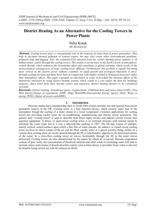
- 1. IOSR Journal of Mechanical and Civil Engineering (IOSR-JMCE) e-ISSN: 2278-1684,p-ISSN: 2320-334X, Volume 12, Issue 5 Ver. II (Sep. - Oct. 2015), PP 10-14 www.iosrjournals.org DOI: 10.9790/1684-12521014 www.iosrjournals.org 10 | Page District Heating As an Alternative for the Cooling Towers in Power Plants Neha Kotak (Be Mechanical) Abstract: Cooling towers plays a consequential role in the removal of waste heat in power generation. They help to decimate thermal pollution of natural waters, but may also create other environmental problems, primarily drift and fogging. Also, the estimated CO2 emission from the world's thermal power industry is 10 billion tonnes yearly through the cooling towers. This results in an increase in the Earth's levels of atmospheric carbon dioxide, which enhances the Greenhouse effect and contributes in global warming which results in the meteorological consequences of large cooling tower effluents. Furthermore, this problem is rapidly becoming more critical as the electric power industry continues its rapid growth and ecological objections to once- through-cooling increase and these have been in conjunction with studies related to biological processes rather than atmospheric effects. This paper expounds an alternative in order to preclude the ominous effects of the deleterious emissions by using district heating systems which would in a way utilize the heat for buildings purposes. Since fossil fuels have become scarce and expensive, district heating deserve to be considered seriously. Keywords: District heating; Greenhouse gases; Cogeneration; Combined heat and power plant (CHP); Tera Watt hour(s);Design of experiments (DOE; Mega Watt(MW);International Energy Agency (IEA); Waste to energy (WTE); Master of social work(MSW). I. Introduction Previous studies have estimated that there is 10-40 TWh of heat currently lost and rejected from power generation sources in the UK. Cooling tower is a heat rejection device, which extracts waste heat to the atmosphere though the cooling of a water stream to a lower temperature. Common applications for cooling towers are providing cooled water for air-conditioning, manufacturing and electric power generation. The generic term "cooling tower" is used to describe both direct (open circuit) and indirect (closed circuit) heat rejection equipment. A direct, or open-circuit cooling tower is an enclosed structure with internal means to distribute the warm water fed to it over a labyrinth-like packing or "fill." The fill may consist of multiple, mainly vertical, wetted surfaces upon which a thin film of water spreads. An indirect, or closed circuit cooling tower involves no direct contact of the air and the fluid, usually water or a glycol mixture, being cooled. In a counter-flow cooling tower air travels upward through the fill or tube bundles, opposite to the downward motion of the water. In a cross-flow cooling tower air moves horizontally through the fill as the water moves downward. Cooling towers are also characterized by the means by which air is moved. Because evaporation consists of pure water, the concentration of dissolved minerals and other solids in circulating water will tend to increase unless some means of dissolved-solids control, such as blow-down, is provided. Some water is also lost by droplets being carried out with the exhaust air (drift).
- 2. District Heating As an Alternative for the Cooling Towers in Power Plants DOI: 10.9790/1684-12521014 www.iosrjournals.org 11 | Page Fig no1 .types of cooling towers Explicating the crucial work of the cooling tower, the fact that it is deleterious cannot bepretermit because of its: 1.1 Immense Water usage Cooling towers, as well as being more expensive, work by evaporating a lot of water, placing stress on supplies of fresh water – they use 1.8 L/kWh according to the report, compared with less than 0.4 L/kWh for once-through cooling. The NETL report noted that the projected increase in coal-plant water use over the next two decades if direct cooling is no longer allowed on new plants does not factor in the likelihood that many coal plants will add carbon capture and storage (CCS) technology to constrain US carbon emissions, thereby increasing water consumption by a further 30-40%. Wet cooling towers give rise to water consumption, with up to 3.0 litres being evaporated for each kilowatt-hour produced, depending on conditions. This evaporative water loss by phase change of a few percent of it from liquid to vapour is responsible for removing most of the heat from the coolant water at the cost of only a small fraction of the volume of the circulating liquid (though a rather large fraction of the water actually withdrawn from lake or stream). Water consumption by evaporation is reckoned to be typically about double that with direct cooling .Cooling towers with recirculating water reduce the overall efficiency of a power plant by 2-5% compared with once-through use of water from sea, lake or large stream, the amount depending on local conditions. A 2009 US DOE study says they are about 40% more expensive than a direct, once-through cooling system.Dry cooling towers which retrofit to air cooling decreases efficiency by 3-10% and is reported to cost about $200 million per 1000 MWe capacity.*Australian projected figures for coal show a 32% drop in thermal efficiency for air cooling versus water, eg from 33% to 31%. A 2010 study by the Electric Power Research Institute (EPRI) found that the total cost of retrofitting US power plants with cooling towers would exceed $95 billion. 1.2 Catastropic Environmental effects caused by the cooling towers Being very large structures, cooling towers are susceptible to wind damage, and several spectacular failures have occurred in the past. At Ferrybridge power station on 1 November 1965, the station was the site of a major structural failure when three of the cooling towers collapsed owing to vibrations in 85 mph (137 km/h) winds.In the case of direct cooling, impacts include the amount of water withdrawn and the effects upon organisms in the aquatic environment, particularly fish and crustaceans. This latter includes both kills due to impingement and entrainment and the change in ecosystem conditions brought about by the increase in temperature of the discharge water. EPRI’s study encompassed 428 US power plants with once‐through cooling systems which were potentially subject to revised US Environmental Protection Agency regulations ostensibly to protect aquatic life from being caught up in the cooling water intake structures. A change in the design would cost $305 per head for 311 million US citizens to retrofit all once‐through cooling system power plants .While ,in the case of wet cooling towers, impacts include water consumption (as distinct from just abstraction) and the effects of the visual plume of vapour emitted from the cooling tower. Many people consider such plumes as a disturbance, while in cold conditions some tower designs allow ice to form which may coat the ground or nearby surfaces. Another possible problem is carryover, where salt and other contaminants may be present in the water droplets.
- 3. District Heating As an Alternative for the Cooling Towers in Power Plants DOI: 10.9790/1684-12521014 www.iosrjournals.org 12 | Page 1.3 Shutdown and maintenance issues Cooling tower shutdown maintenance is also very complex and time consuming. Shutdown maintenance occurs when the components are not functioning properly which reduces the performance of the cooling tower. II. District heating systems District Heating has proven to be a major contributor to Greenhouse Gas (GHG) reduction in many member countries and recognition of DH's importance is growing. In fact, many countries where it is established are renewing their commitment to DH as they find new ways to use the technology to reduce environmental impacts. DH facilitates linkages between supplies that are environmentally desirable and end users that could not otherwise make use of those energy sources. 2.1 Working of district heating A thermal plant supplying energy to a district heating system is made up of three principal components. The first is the thermal production plant, which provides the hot water or. The boilers burn solid waste along with fossil fuels or can be dedicated boilers thatburn only solid waste.The second component of the thermal energy system is the transmission and distribution network. This network conveys heat, in the form of steam, hot water, or chilled water, through pipes from the thermal plant to the customers.The third component of the thermal energy system is the customers’ in-buildingequipment. Steam or hot water supplied by the thermal system is directed into thebuilding and circulated through the customer’s equipment. In the case of hot watersystems and newer steam systems, heat exchangers are used frequently, and manybuilding space heating and domestic water heating systems are of hot water design. Fig no 2. Energy consumption for heating by sub sector and end use in TWh(2011) Whenchilled water is also distributed by the system, water-to-water heat exchangers are usually employed within the building. Heat exchangers isolate the user from the thermal systemand preserve integrity of both system and customers. Energy loss in this approach is verylow.The transmission and distribution system transports thermal energy through a network ofinsulated pipes. The pipe loop carries energy in the form of steam or hot or chilled waterto the end users. A separate pipe returns water with most of the energy removed to theproduction plant for reprocessing. Insulated pipes can be buried directly in the ground,placed in tunnels or above ground. A typical steam piping system normally servicescustomers within two to three miles of the generating source. Hot water, on the other hand, can be piped over distances of up to 32 km (20 mi) with limited heat loss. III. Technical aspects of a district heating system in an exixting thermal plant 3.1Pre-Insulated Piping for district heating In the U.S., there are some companies that fabricate pre-insulated pipes. One of them is Thermacor, with over 40 years experience in the industrial, commercial, and militarypiping markets, utilizes the latest in polyurethane foam, polyisocyanurate foam, and other high temperature insulation technology to manufacture pre-insulated, pre-fabricated piping systems specifically for individual project requirements. It produces pipes for high temperature systems, above 120 ºC (250 ºF).
- 4. District Heating As an Alternative for the Cooling Towers in Power Plants DOI: 10.9790/1684-12521014 www.iosrjournals.org 13 | Page 3.2 Leak Detection System Today, piping system can incorporate a leak detection device that can be monitored through out the life of the piping system. The name of this device is Electric Resistance Monitoring (ERM) system. This system is simple and easy to install that anymanufacturer should incorporate in their system. In fact, the European market has beenusing ERM in their products for the past two decades. 3.3 Retrofitting a thermal plant Most of the existing power plants in the United States are of a single-purpose, condensingtype, and are not designed for extraction of large amounts of steam as required for DH. For example, in a typical fossil-fueled power plant, the exhaust steam flow into the condenser constitutes about 60 – 65% of the throttle steam flow. For district heating purposes, a substantial part of this steam must be extracted from the turbine stages beforeit reaches the condenser .The electricity lost because of cogeneration depends on the extracted steam flow rate, pressure and number of extractions. The ratio of the electricity lost to the heat supplied from the turbine depends on turbine design and may range 0.1 to 0.2 kWh of electricity per kWh of thermal energy obtained. Fig no 3.Combined Heat and powercapacities,technologies and grade of heat. When considering the conversion of existing steam turbines to district heating operation,the possibility of extracting up to 15- 20% of the throttle steam flow from the crossoverpoint of the turbine should be considered. An additional pressure control system mayhave to be installed at the crossover pipe to provide reliable operation of the turbineunder district heating conditions.It is important to note that the retrofitting of existing turbines to extract the requiredsteam flow for DH is difficult and involves a significant redesign of the turbine and itscontrol system. As a result, a substantial outage time may be necessary for modification.For example, three months outage time was required to install a piping and controlsystem to extract steam from crossover of a 160-MW turbine. 3.4 Piping Distribution Network The distribution network is comprised of pipes buried underground. Two sets of pipes:one to circulate the heated water to the consumers and the other to return the water backto the plant for reheating, are buried side by side in a trench. The network can take theform of a radial system or a looped system.The radial system is cheaper than the looped system. However, the looped system offersgreater reliability because water can be circulated from two directions. Thus, during shutdowns for repairs, only customers between the two shutoff points will be affected.The pipes are placed in trenches in the ground at a minimum depth of 600 mm. This isusually sufficient to withstand surface loads. It is not necessary to place the pipes belowthe frost line in cold climates because the constant circulation of water prohibits freezingand a high insulation value results in low heat loss. In cases where the ground does freeze to the depth of the pipes, insulation reduces heat loss to acceptable levels.Depending on the scale of the system and temperature at which the water is circulated,the pipes can either be prefabricated steel or plastic. Prefabricated plastic pipes are usedin situation in which the temperature of the water does not exceed 95 ºC. These pipes arecheaper and easier to install than steel pipes.
- 5. District Heating As an Alternative for the Cooling Towers in Power Plants DOI: 10.9790/1684-12521014 www.iosrjournals.org 14 | Page IV. Advantages and benefits District heating networks provide major advantages like enabling the efficient transportation and use of heat for a wide variety of users, allowing a broad range of energy generation technologies to work together to meet demand for heat, enabling fuel flexibility, helping to efficiently manage supply and demand of energy, lowering costs of energy generation, dramatically increasing fuel efficiency through use of CHP and reducing labour and maintenance cost as compared to individual systems. These in turn deliver a range of beneficial outcomes as it provides a means of securing significant reduction in CO2 emissions through the optimisation of heat supply ,extends the reach of renewables, by using renewable heat efficiently and by providing opportunities for the deployment of renewable technologies that otherwise wouldn’t be viable and improving security of supply. The IEA DHC deals with the design, performance and operation of distribution systems and consumer installations. The work programme is mostly carried out through joint, cost-shared activities and some task- sharing activities are also underway. 4.1 Environmental Benefits A significant advantage of a DH system fueled by MSW is the potential for reducingenvironmental pollution. The environmental benefits are derived through systemefficiency resulting from the WTE plants producing a higher ratio of units of usefulenergy to emissions. For example, the carbon dioxide savings from co- generating 1 MWhof electricity are approximately 500 kg., as compared to a separate production of heat andelectricity in a conventional power plant. Another benefit of DH is the potential for reduction of thermal discharges to lakes, andrivers. The rejection of waste heat from cooling towers will decrease, significantly duringthe winter months.thermal plant technologies have incorporated air pollution control systems (APC) that minimize environmental impacts so that electricity produced by these plants has a lower environmental impact than that from coal-fired power plants. Obtaining thermal energy from plants, in addition to electricity, has obvious economic and environmental benefits. In addition, combustion of wastes in plants reduces the amount of waste to be landfilled,80% in terms of mass. And, it eliminates the danger of contaminating groundwater byleachate from landfills as well as avoids the contamination of land for future developments. V. Conclusion Waste-to-Energy technology and district heating and cooling systems are complementary solutions for several reasons. First, waste that is used locally as the fuel to power the thermal plant avoids methane and other emissions at distant landfills and also reduces the use of non-renewable fossil fuels. Second, a district heating and cooling system providesa centralized and efficient way to supply heating and cooling to a residential and/or commercial area, thereby increasing the thermal efficiency of the WTE substantially and also avoiding the uncontrolled emissions of thousands of residential and commercial boilers. There are numerous conditions for proposing district heating in the U.S. using WTE plants, especially in the northern regions. First, northeastern cities are densely populated, have cold winters, and large heating expenditures in the cold months of the year. Second, the technologies for retrofitting a thermal plant and building a district heating are available and proven within the U.S. Third, there is an ample supply of MSW to fuel new thermal plants, or expansions of existing power plants. References [1]. District heating :The role of district heating in energy supply. [2]. Department of energy and climate change. [3]. Author P.K.NAG,‘‘Power plant engineering by’’. [4]. Author M.M.EI-WAKIL,‘‘Power plant technology’’. [5]. F.A HUFF,R.C BEEBE,D.M.A.JONES,G.M.MORGEN.JR and R.G.SEMONIN,‘‘Effects of cooling towers effluents on atmospheric conditions in northeastern Illinois’’. [6]. Bard Skagestad , Peter Mildenstein, ‘‘Programme of Research ,Development and Demonstration on District Heating and Cooling’’ [7]. Priscilla Ullo, ‘‘Potential for Combined Heat and Power and District Heating and Cooling from Waste to-Energy Facilities in the U.S.-Learning from the Danish Experience” [8]. D.G.Kr Iger,‘‘Air cooled heat exchangers and cooling towers’’