
Recommended
More Related Content
Similar to phase 1 presentation-1.pdf
Similar to phase 1 presentation-1.pdf (20)
Recently uploaded
Recently uploaded (20)
phase 1 presentation-1.pdf
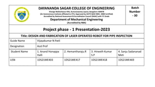
- 1. Project phase - 1 Presentation-2023 DAYANANDA SAGAR COLLEGE OF ENGINEERING Shavige Malleshwara Hills, Kumaraswamy Layout, Bangalore-560078 (An Autonomous Institute affiliated to VTU, Approved by AICTE &ISO 9001: 2008 Certified) Accredited by National Assessment & Accreditation Council (NAAC) with ‘A’ Grade Department of Mechanical Engineering (Accredited by NBA) Title: DESIGN AND FABRICATION OF LASER OPERATED ROBOT FOR PIPE INSPECTION Guide Name Vijayakumar N Patil Designation Asst Prof Student Name 1. Anand Honappa Halli 2. Hemantharaju.R 3. Hineeth Kumar S.P 4. Sanju Sadananad Meti USN 1DS21ME403 1DS21ME417 1DS21ME418 1DS21ME469 Batch Number - 30
- 2. Contents : • ABSTRACT • INTRODUCTION • LITERATURE REVIEW • OBJECTIVES OF THE PROJECT • METHODOLOGY • BLOCK DIAGRAM • WORKING PRINCIPLE • CONCEPT DRAWING • DESIGN UPDATE OF THE ROBOT • FLEXIBLE MECHANISM • DESIGN CALCULATIONS • PROJECT PROCESS • EXPECTED OUTCOMES OF THE PROJECT • REFERENCES
- 3. Abstract: A pipe inspection robot is device that is inserted into pipes to check for obstruction or damage. These robots are traditionally manufactured offshore, are extremely expensive, and are often not adequately supported in the event or malfunction. This had resulted in associated environmental services limited. A New Zealand utilize of this equipment, facing significant periods of down time as they wait for their robots to be the repaired. Recently, they were informing that several robots were no longer supported. This project was conceived to redesign the electronics control systems one of these PIR, utilizing the existing mechanical platform. Requirements for the robot were that it must operate reliably in confined, dark and wet environments and provides a human wears with a digital video feed of the internal status of the pipes. There robot should as much as possible incorporate off the shaft components, cheap, and potentially onsite repair. This project details the redesign and constructions of such robots. It employees there electronic boards integrated with mechanical components and provides video or wave signal feedback via custom graphical interface although at the prototypes state the electronics has been successful with cost of less than a length of the original robot purchase prize.
- 4. Introduction: Pipeline is the major tool of transportation. Many kinds of pipes are being utilized to construct important lifelines such as water and gas supply in our contemporary society. Also pipes are widely used in chemical industries and in gulf countries for carrying petrol, diesel, oil etc. But recently many troubles are occurring in the pipelines because of natural calamities and mechanical damages from third parties and defects are occurring in the pipelines. If the defects in the pipe are caused by aging, corrosion, rust and nature calamity then it is difficult to find out the defects and the place of the defects, and also there is great amount of loss. Thus scheduled inspection must be done. If we decide to do this inspection manually then large amount of time, effort and labour is necessary to grub up the pipes that are buried in the ground. If the robot can inspect inside the pipes, fast and accurate examination is able to do at low cost. Pipeline is the major tool for fluid transformation. Various kinds of pipes are being used to construct important lifelines such as water and gas supply in our contemporary society. Robotics is one of the fastest growing engineering field nowadays. To reduce the defective level in the pipe and mechanical damages which are possible. Recently, many researchers have been studying robotic systems capable of moving freely inside the pipes. The three finger mechanism will be attached to the robot system to move inside the pipe and balancing the body weight and work with the help of LDR system to detect the defects inside the pipe. The Laser Pipe Inspection Robot represents a significant leap forward in non-destructive testing methods, offering a versatile and adaptable solution for a wide range of applications. Its primary objective is to enhance the efficiency and reliability of pipeline inspections, ultimately contributing to the longevity and performance of infrastructure systems.
- 5. Literature Review: ● M.R.NAEEM (2011) wok likely focuses on the design and development of a pipe inspection robot. A literature survey in this area could involve exploring Naeem’s publications and related research papers discussing various aspects of pipe inspection robots. Look for details on the robot’s design, functionalities, the technology used for inspection, maneuverability within pipes, data collection methods, and any advancements proposed in the field of pipeline inspection. This survey will provide insights into the evolution of pipe inspection robotics and the innovations contributing to more effective maintenance of pipeline infrastructure. ● Bi Bi Kadejatul Kubra (2020) In a prototype made by their objective is to clear the blocking part by the means of milling operation. Their proposed model is a wall press type robot. Compared to this model our model does not clear the obstruction rather it sends the footage of pipe channel inside to the user about the blockage by the means of continuous data transmission by the camera module. Their model cannot detect cracks and breaks where as our robot will send the whole footage thus enabling the user to identify any obstruction, cracks or corrosion. Hence, the user would be able to do something above it. ● Peng Li, Mengjun Fang (2018) in this paper they have used screw drive helical wheels operated robot and they used it for multiple use like horizontal pipe, elbow pipes and cross pipes ,they have done lot of calculations with varying different angles ,but they have used n number of linkages and only two side of the wheel system , it is difficult to balance the self weight of the robot while working for that reason we are divided the angle by three and arranged the wheels at 120degree each which can balance them self.
- 6. ● Mrs. M. Shobha ,B, Srinivas Rao(2023) In this prototype, to tackle the challenges they have proposed a screw driver type wall press adaptable robot. It has rotor, stator, and control unit. This model does not have any camera installed, their main goal is only to fit the robot inside the pipes and it only works for ranges 127mm to 152mm. ● Atul A. Gargade1 (2006) presented different angle fore leg system to control the robot with various angles of moments, in this mechanism movement is copied from both the inchworm and the wall press type in nature. In- pipe inspection robot are able to move freely inside the straight pipe, T joints, elbow of different diameters by using electronic parts we can develop IOT version in future. ● Varshil . H Patel , Prof.Neel M. Joshi (2023) In this paper two wheeled type in pipe mini robots are proposed. And very important design goal of these robotics is adaptability, here their robot is that friction between the pipe and cables for communication system but we are using dc motor to each wheel and the speed control can be possible and robot moves smoothly in the pipe. ● Ankit Nayak, S. K. Pradhan (2014) Here they used single actuator in screw drive mechanism with one DOF and this robot is ranging from diameter 127mm to 152 it can possibly move in vertical, horizontal and inclined pipe and they used model of IPIR based on screw drive mechanism. To operate a single robot for both vertical and horizontal may be lot of difference is there so we are specially focusing on horizontal pipes.
- 7. Objectives of the Project: : The construction of the robot will depends upon the number of links and the LDR system is the main source to detect the crack of the pipe, the robot wheels are operated by the help of four bar mechanism . Therefore, the objectives of our project are: 1. To make an adaptive robotic design having three finger mechanism Cylindrical structure so as to move smoothly through the pipe. 2. Add gripper or claw and LDR system to which it can contract and expand according to necessity and can detect the crack detection on the pipe using concept of reflection. 3. To interface it with the controller unit, sensor unit and display unit and camera is mounted over it with the laser light . Also laptop and mobile is interfaced for visual display. 4. This reduces the time and the cost of replacing the cracked pipes
- 8. BLOCK DIAGRAM POWER SUPPLY ATMEGA 16 MANUAL RESET DC MOTOR MOTOR DRIVE DC MOTOR ESP32CAM RF MODEM TEMPERATURE SENSOR CO2 SENSOR LDR MOTOR DRIVE DC MOTOR DC MOTOR
- 9. METHODOLOGY The robot will perform the following steps for performing the task: 1 .The robot firstly goes down the pipe with by adjusting its three finger mechanism according to the dimensions. It is controlled by the operator using keypad of laptop 2 .The video camera mounted on it gives the insight view of the position and LDR Is also placed. 3 .The robot then grasps the target by contracting or expanding its gripper according to the requirement and then after grasping it continues moving and then starts detecting the crack on the pipe. 4 .Sensing is also done by the robot which is monitored on terminal display. 5 .The robot holds the target tightly and brings it out of the pipe safely. IR sensors are used to detect if there is any harmful smell the affects the flow. 6 . And if there is any crack detected on the pipe then it sends the information to the user.
- 10. Working Principle: Figure - Block diagram of working principle
- 11. Working Principle: • Deployment: The pipe inspection robot is deployed at the entry point of the pipeline. • Navigation: The robot moves through the pipeline using wheels , guided by sensors to detect cracks and navigate efficiently. • Camera Activation: Once in position, the robot activates its cameras, equipped with lights, to capture images and videos of the pipe's interior. • Image Processing: Captured visuals are processed onboard or transmitted to a control center, where image processing algorithms identify and analyze anomalies such as crack. • Laser sensing: when laser light reflect back to the LDR sensor senses the light & gives the output.
- 12. Concept design
- 13. Design Update of the robot: Fig A. 3D Structure Of Robot Fig B. Front View Fig C. Side View Fig D. Top View
- 14. Cad Simulation of robot
- 16. Flexible mechanism: Fig a. The Horizontal View Of The Flexible Mechanism Of The Robot Fig b. The Top View Of The Flexible Mechanism Of The Robot Here in this there are three sets of flexible wheel mechanisms are integrated in the robot, and all their structures are completely same. • Each of these flexible wheel mechanisms consists of three units: the driving mechanism, the linkage clutch mechanism and the wheel units, shown as in Fig. a and Fig. b, respectively. • In order to be more compact and more flexible, a screw rod is applied to replace the traditional spring axe, which was used in Young (2010) and Young (2012), and an improved 4-bar structure is designed for the linkage clutch mechanism, compared with the design in Fa (2015). • Every wheel unit is composed of two sets of wheels and every wheel set consists two wheels. • Each wheel set is driven by a DC motor, which is equipped with a worm gear box, as shown in Fig. 5.
- 17. • The force relationship between the force on the wheels and the pressure on the sliders is shown as in Fig. c. • Through this relationship and the pressures measured by the pressure sensors, the pressures and the friction forces between the wheels and the pipeline inner surface can be calculated. • The friction forces are caused by the pressures, and suitable friction forces ensure the robot moving smoothly. • Therefore, these pressures and friction forces are critical to the dynamics of the robot. Fig c. The force analysis of the linkage clutch mechanism The length of the bar PE is l . The length of ME and the slider bar SE can be considered to be the same, which is represented as l ‘. The torque on point P relative to point E, which is Tp , and the torque on point M relative to Point E, which is TM, are equal, described in equation (1) Tp = Tf …………………………………………………..(1) The torque on point P relative to point E can be calculated as: Tp = FP ·cos θ l +Ff · sin θ l = Fp ·l ·(cos θ +µ · sin θ) …………. (2) where Fp is the pressure on the P point, Ff is the friction between the wheels and the pipeline inner surface and µ is the friction coefficient. The torque on point S relating to point E is: Tf = F1·l’ …………………………………….(3)
- 18. Therefore, F1 can figure out. Then through dividing F1, the force on the slider bar F2 is: F2 = F1 · cos(α − 90◦ ) ……………………………… (4) Because α = 180◦ − 2θ, F2 can be represented as: F2 = F1 · cos(180◦ − 2θ − 90◦ ) = F1 · sin(2θ) ……… (5) pressure on the slider Fs, which is collected by the pressure sensor, can be got by dividing F2: Fs = F2 · cos θ………………………………………….. (6) 1.Design calculations of screw rod: According to these below specification we can use to calculate the required parameters: mass acting on the linear slider mechanism(M) , Stroke length(L), Maximum transverse speed(N), Guideway type, co-efficient of friction, Drive motor type . Etc Below relations and conditions are used to calculate all the parameters: • Selection of accuracy grade from data handbook • Selection of lead From the maximum rotational speed of AC motor: l ≥ Vmax / Nmax (mm) • Selection of screw shaft diameter from data handbook • Decision of screw length Screw length Lo is: Lo = Stroke + nut length + margin + shaft end length (mm) • Normally, the overall screw shaft length Lo less than or equal to 70 times of screw shaft diameter d is recommended. Therefore, screw shaft diameter d is: d ≥ Ls /70 (mm)
- 19. • Allowable axial load: Calculation of allowable axial load Accelerating/decelerating time is: α = V/ 60 t Where t is time in sec/cycle F1 = mg – mα (N) F2 = mg (N) F3 = mg + mα (N) 2.Motor calculations : • FORCE CALCULATIONS F= M* g (Newton) Where M = mass of the robot in kg g= acceleration due to gravity • Load torque T=F*R (n/mm) Where T = torque in n/mm F = force in N R = wheel radius in mm • Power calculations P=2𝜋NT / 60 (kw) Where N = speed
- 20. PROJECT PROGRESS: The project was already planned to be carried out in multiple stages. In the initial stage, we do research about the topic and did the literature survey along with that we came up with a problem statement. After the literature survey, we understand some basic concepts regarding robot mechanism which including three finger mechanism and LDR system attached to it with in front of the camera ,,,,,,, . The motion of the flexible mechanisms are controlled by the MCU based on the pressure data between the wheels and the pipeline inner surface, which are related to the pressures between the connector slider and the U-shape slider. In normal straight pipeline without diameter transformation, the pressures are within the threshold ranges. For some special pipelines, such as oil pipelines, the friction between the wheels and the pipeline inner surface, which is decided by the pressure between them, must be big enough to guarantee However, when the inner diameter of the pipeline changes, the pressures on the wheels will change, and the pressures between the sliders will transform accordingly. The flexible mechanisms will contract when the pressures exceed the threshold ranges when the pipeline inner diameter changes into smaller, for example, there is an obstacle or a corner. On the contrary, the flexible mechanisms will extend when the pressures reduce lower than the threshold ranges.
- 21. Expected Outcomes 1. Functional Robot: A working pipe inspection robot for diverse pipes. 2. Accurate Data: Precise data on pipe conditions through sensors. 3. Efficiency & Safety: Safer, faster, and cost-effective inspections. 4. Compliance: Compliance with inspection regulations. 5. Environmental Impact: Reduced environmental footprint during operations
- 22. BUDGET DETAILS SL .NO Particulars Cost 1 Arduino Rs 650 2 IR sensors Rs 208 3 LDR Rs 180 4 Temperature sensor Rs 300 5 RF modem Rs 1800 6 DC motors (6) stepper motor 200 × 6 = Rs 1200 Rs 969 7 H Bridge (3) 400 ×3 = Rs 1200 8 Power supply battery and power adapter Rs 1500 9 Mechanical fabrication Rs 6000 10 Total Rs 14,007
- 23. • Christian, M., Simon, P., Leif, H., Kasper, L. and Zhenyu, Y. (2016). Subsea Infrastructure Inspection: A Review Study. proc. of IEEE 6th International Conference on Underwater System Technology: Theory and Applications, 71-76. • Iszmir, I., Adzly A., Khairul S., Mohd B., Muhammad J. and Juniza S. (2012). Development of In-pipe Inspection Robot: a Review. Conference on Sustainable Utilization and Development in Engineering and Technology, 310- 315. • Young, Kwon and Byung, Y. (2012). Design and Motion Planning of a Two-Module Collaborative Indoor Pipeline Inspection Robot. IEEE Transactions On Robotics, volume 28, 681-696. • Jong, K., Gokarna S., and S. I. (2010). FAMPER: A fully autonomous mobile robot for pipeline exploration. IEEE International Conference on Industrial Technology , 517-523 • Aaqib Husain ,Sheik Fazil Amin , Mir Saquib Hussain (2018 ) 'Pipe inspection robot', International Research Journal of Engineering and Technology, 05(07), pp. 280-281 [Online]. Available at: www.irjet.net › archives › IRJET-V5I749 (Accessed: 2- 05- 2020). • Pooja G.M, Kavyashree MS, Niharika SN, Chandrashekhara G N (2018) 'Inpipe Inspection Robot', International Journal of Engineering Research & Technology, 6(Special Issue -13), pp. 2-5 [Online]. Available at: https://www.ijert.org/research/inpipe- inspection-robot-IJERTCONV6IS13101.pdf (Accessed: 2-05-2020). • Ankit Nayak, Ankit Nayak (2014) 'Design of a New In-Pipe Inspection Robot', 12th GLOBAL CONGRESS ON MANUFACTURING AND MANAGEMENT, GCMM 2014, (Procedia Engineering 97 ( 2014 ) ), pp. [Online]. Available at: www.sciencedirect.com (Accessed: 02-05-2020).K. Elissa, “Title of paper if known,” unpublished. • Data hand book (https://www.technico.com/pdf/blog/15%20Ball%20Screw.pdf). References: