
Recommended
More Related Content
What's hot
What's hot (20)
Similar to Leak Tests.pptx
Similar to Leak Tests.pptx (20)
Recently uploaded
Recently uploaded (20)
Leak Tests.pptx
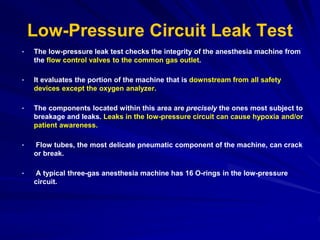
- 1. Low-Pressure Circuit Leak Test • The low-pressure leak test checks the integrity of the anesthesia machine from the flow control valves to the common gas outlet. • It evaluates the portion of the machine that is downstream from all safety devices except the oxygen analyzer. • The components located within this area are precisely the ones most subject to breakage and leaks. Leaks in the low-pressure circuit can cause hypoxia and/or patient awareness. • Flow tubes, the most delicate pneumatic component of the machine, can crack or break. • A typical three-gas anesthesia machine has 16 O-rings in the low-pressure circuit.
- 2. Cont • Leaks can occur at the interface between the glass flow tubes and the manifold and at the O-ring junctions between the vaporizer and its manifold. • Loose filler caps on vaporizers are a common source of leaks, and these leaks can cause patient awareness under anesthesia. • Several different methods have been used to check the low-pressure circuit for leaks, including the oxygen flush test, the common gas outlet occlusion test, the traditional positive-pressure leak test. • The check valve is located downstream from the vaporizers and upstream from the oxygen flush valve. • It is open in the absence of backpressure. Gas flow from the manifold moves the rubber flapper valve off its seat and allows gas to proceed freely to the common outlet.
- 3. Cont • The valve closes when backpressure is exerted on it. • Backpressure sufficient to close the check valve may occur with the following conditions: 1) oxygen flushing, 2) peak breathing circuit pressures generated during positive-pressure ventilation, 3)use of a positive-pressure leak test. • Generally , the low-pressure circuit of anesthesia workstations without an outlet check valve can be tested with a positive-pressure leak test, and machines with check valves must be tested with a negative-pressure leak test.
- 4. Positive& Negative-Pressure Leak Test • When performing a positive-pressure leak test, the operator generates positive pressure in the low-pressure circuit by using flow from the anesthesia machine or from a positive-pressure bulb to detect a leak. • When performing a negative-pressure leak test, the operator creates negative pressure in the low-pressure circuit by using a suction bulb to detect leaks.
- 5. Inappropriate use of the oxygen flush valve to check the low-pressure circuit of an Ohmeda machine equipped with a check valve. The area within the rectangle is not checked by inappropriate use of the oxygen flush valve. The components located within this area are precisely the ones most subject to breakage and leaks. Positive pressure within the patient circuit closes the check valve, and the value on the airway pressure gauge does not decline despite leaks in the low-pressure circuit
- 7. 250 Liters
- 8. Pressure = 30 cmH2O
- 9. Negative-Pressure Leak Test • It is performed with a negative-pressure leak-testing device, which is a simple suction bulb. • The machine's master switch, flow control valves, and vaporizers are turned off. • The suction bulb is attached to the common fresh gas outlet and squeezed repeatedly until it is fully collapsed. • This action creates a vacuum in the low-pressure circuitry. • The machine is free of leaks if the hand bulb remains collapsed for at least 10 seconds. • A leak is present if the bulb reinflates during this period. • The test is repeated with each vaporizer individually turned to the “on” position because internal vaporizer leaks can be detected only with the vaporizer turned on.
- 11. Food and Drug Administration negative-pressure leak test. Left, A negative-pressure leak- testing device is attached directly to the machine outlet. Squeezing the bulb creates a vacuum in the low-pressure circuit and opens the check valve. Right, When a leak is present in the low- pressure circuit, room air is entrained through the leak and the suction bulb inflates.
- 12. Negative-Pressure Leak Test • If the bulb reinflates in less than 10 seconds, a leak is present somewhere in the low-pressure circuit. • Therefore, it differentiates between breathing circuit leaks and leaks in the low- pressure circuit. • The “universal” negative-pressure leak test is the most sensitive of all contemporary leak tests because it is not dependent on volume. • That is, it does not involve the use of a breathing bag or corrugated hoses whose compliance could mask a significant leak. • It can detect leaks as small as 30 mL/min. • Finally, the operator does not need detailed or in-depth knowledge of proprietary design differences. If the operator performs the universal test correctly, the leak will be detected
- 13. Circle System Tests • The circle system tests evaluate the integrity of the circle breathing system, which spans from the common gas outlet to the Y-piece . • It has two parts—the leak test and the flow test. • To thoroughly check the circle system for leaks, valve integrity, and obstruction, both tests must be performed preoperatively. • The leak test is performed by closing the pop-off valve, occluding the Y-piece, and pressurizing the circuit to 30 cm H2O with the oxygen flush valve. • The value on the pressure gauge will not decline if the circle system is leak free, but this does not ensure valve integrity. • The value on the gauge will read 30 cm H2O even if the unidirectional valves are stuck shut or the valves are incompetent.
- 14. Cont • The flow test checks the integrity of the unidirectional valves, and it detects obstruction in the circle system. • It can be performed by removing the Y-piece from the circle system and breathing through the two corrugated hoses individually. • The valves should be present, and they should move appropriately. • The operator should be able to inhale but not exhale through the inspiratory limb and able to exhale but not inhale through the expiratory limb. • The flow test can also be performed by using the ventilator and a breathing bag attached to the “Y”-piece.
- 15. Workstation Self-Tests • As mentioned previously, many new anesthesia workstations now incorporate technology that allows the machine to either automatically or manually walk the user through a series of self-tests to check for functionality of the electronic, mechanical, and pneumatic components. • Tested components commonly include the gas supply system, flow control valves, circle system, ventilator, and, in the case of the Datex-Ohmeda Anesthesia Delivery Unit (ADU), even the Aladin cassette vaporizer. • One particularly important point of caution with self-tests should be noted on systems with manifold-mounted vaporizers such as the Dräger Medical Fabius GS and the Narkomed 6000 series. • A manifold-mounted vaporizer does not become part of an anesthesia workstation's gas flow stream until its concentration control dial is turned to the “on” position. • Therefore, to detect internal vaporizer leaks on this type of system, the “leak test” portion of the self-diagnostic must be repeated separately with each individual vaporizer turned to the “on” position. • If this precaution is not taken, large leaks that could potentially result in patient awareness, such as from a loose filler cap or cracked fill indicator, could go undetected.
- 16. Low-Pressure System • Check Initial Status of Low-Pressure System: a. Close the flow control valves and turn the vaporizers off. b. Check the fill level and tighten the vaporizers’ filler caps. Perform Leak Check of Machine Low-Pressure System: a. Verify that the machine master switch and flow control valves are OFF. b. Attach a “suction bulb” to the common (fresh) gas outlet. c. Squeeze the bulb repeatedly until it is fully collapsed. d. Verify that the bulb stays fully collapsed for at least 10 seconds. e. Open one vaporizer at a time and repeat steps c and d as above. f. Remove the suction bulb and reconnect the fresh gas hose. Turn on Machine Master Switch and All Other Necessary Electrical Equipment. Test Flow Meter : a. Adjust the flow of all gases through their full range while checking for smooth operation of the floats and undamaged flow tubes. b. Attempt to create a hypoxic O2/N2O mixture and verify correct changes in flow and/or alarm.
- 17. Scavenging System • Adjust and Check Scavenging System: a. Ensure proper connections between the scavenging system and both the APL (pop-off) valve and ventilator relief valve. b. Adjust the waste gas vacuum (if possible). c. Fully open the APL valve and occlude the Y-piece. d. With minimum O2 flow, allow the scavenger reservoir bag to collapse completely and verify that the absorber pressure gauge reads about zero. e. With the O2 flush activated, allow the scavenger reservoir bag to distend fully and then verify that absorber pressure gauge reads less than 10 cm H2O.