SlideShare a Scribd company logo
1 of 54
Download to read offline
1
Design Document for
RENOVATE NEURO-REHABILITATION IN
BLADDER FUNCTION
Submitted to:
Dr. Shriram Pillapakkam
ENGR 4296: Senior Design Project II
Temple University
College of Engineering
1947 North 12th
Street
Philadelphia, PA 19122
19 April, 2017
Prepared by:
H. Smith, G. Bloise, K. Mariner, J. Dominic
Faculty Advisor: Dr. Michel Lemay & Dr. Michael Ruggieri
Neurological Rehabilitation Advocates
Temple University
College of Engineering, Department of Bioengineering
1947 North 12th
Street
Philadelphia, PA 19122
For further information, please contact Dr. Shriram Pillapakkam (email:
shriram.pillapakkam@temple.edu)
2
Team SD2—23 Neurological Rehabilitation Advocates
Team Members Haley Smith, Gina Bloise, Kelsey Mariner, Jessica Dominic
Advisor(s) Dr. Michel Lemay
Coordinator Dr. Michael Ruggieri
Department(s) Bioengineering, Cell Anatomy and Biology
Project Title Renovate Neuro-rehabilitation in Bladder Function
Abstract
This project involves redesigning the Avery Breathing Pacemaker phrenic
nerve/diaphragm electrode, currently in use as a breathing pacemaker, for
application as a nerve cuff electrode to reinstate bladder function in
individuals suffering from spinal cord injuries. Our project development
focuses on the physical re-design of the electrode so it complies with the
biological parameters of the lower urinary tract. We intend to enhance the
Avery Breathing Pacemaker phrenic nerve/diaphragm electrode by
changing the material properties of the component electrode to maximize
its flexibility and movement capabilities. We will be incorporating a
shape memory alloy into the cuff to allow for easy implantation, as the
cuff will have self-closing capabilities. To ensure optimization of
flexibility and minimize neurological stress, we are also modifying the
connecting leads to have a coiled design. Such modifications will allow
the use of the stimulator/electrode to increase the volumetric capacity of
the bladder and its contractile abilities so that storing and releasing urine
is no longer a worry for those suffering from movement spinal cord
injuries and neurological disorders.
URL
https://sites.google.com/a/temple.edu/renovate-
neurorehabilitation-in-bladder-function/
3
EXECUTIVE SUMMARY:
Bladder dysfunction and urinary tract infections are common in patients with spinal cord injuries
and neurological disorders; stroke, brain trauma, multiple sclerosis, and cerebral palsy, to name a few
(Gaunt et al., 2006), (Sheffler et al., 2007). Renal failure was once the most prominent cause of death
by spinal cord injuries, and though research has lessened this occurrence rate, patients are still at a
high risk (Gaunt et al., 2006). Mechanical device treatment options include catheters, artificial
sphincters, urethral stents, or the intraurethral pump; however, complications and flaws exist within
each (Gaunt et al., 2006). For catheters, there is a high risk of urinary tract infections which can add
stress on the patients; urethral stents do not reinstate regular control of the sphincter; artificial
sphincters are not commonly used to restore bladder function; and finally, intraurethral pumps are
inapt based on the fact that they causes discomfort, urethral dilation and possible urethral damage
(Gaunt et al., 2006).
Within the scope of our senior design project, we will be tasked to redesign and renovate the Avery
Breathing Pacemaker phrenic nerve/diaphragm electrode, currently in use in a breathing pacemaker,
and introduce it into clinical use as a nerve cuff electrode to reinstate bladder function in individuals
suffering from spinal cord injuries. This device is currently responsible for phrenic pacing to provide
respiratory support for patients with chronic respiratory insufficiency, but we plan to repurpose it as
a stimulating nerve cuff electrode specifically for the restoration of bladder function (“Diaphragm
Pacemaker,” n.d.).
Because the current design model we are referencing is based on a system stimulating the
diaphragm, our project development will focus on the physical design of the receiver and electrode
to comply with the biological parameters of the lower urinary tract. For this project, we will be using
the same transmitter and antenna system developed by Avery Biomedical. Recently, the Avery
diaphragm pacemaker system has been used in an animal model for restoring bladder function,
allowing researchers to assess its adaptability. When analyzing the flaws to this system when
exposed to a different anatomical environment, this in turn created the limitations that our project
will aim to conquer. (“Diaphragm Pacemaker,” n.d.).
Modifications to the electrode will begin with its material properties and progress into surgical
implantation. The current design features platinum that is too brittle, an electrode contact surface
that is too thick, a diameter that is too large for the nerve and more. Our new design will address
these flaws and be able to compensate for more movement from the bladder nerves; a part of the
body that undergoes much more movement than the upper respiratory tract.
Overall, we hope that our final design will contribute to improving the lives of those suffering from
incontinence1
due to SCI while also helping to prevent clinical complications.
2
1
Incontinence: lack of voluntary control over urination.
2
Abbreviations that will be used throughout the text: SMA = shape memory alloys, UTI =
urinary tract infection, EMG = electromyography, FES = functional electrical stimulation, SCI =
spinal cord injury, PN = pudendal nerve, EUS = external urethral sphincter, MEAs =
microelectrode arrays, NGF = nerve growth factor, PNS = Peripheral Nervous System
4
TABLE OF CONTENTS
Executive Summary:..................................................................................................................3
Table of Figures.........................................................................................................................6
Table of Graphs .........................................................................................................................7
Table of Tables..........................................................................................................................7
Problem Statement ....................................................................................................................8
Overall Objectives..........................................................................................................................................................8
The Challenge of Interfacing to the Peripheral Nervous System ......................................................................9
Economic and Historical Perspectives .....................................................................................................................10
Spinal Cord Injury and Bladder Incontinence ....................................................................................................10
Neuroprostheses......................................................................................................................................................12
Functional Electrical Stimulation (FES) ..............................................................................................................13
Shape Memory Alloys (SMAs)...............................................................................................................................14
Design Concept............................................................................................................................................................14
Candidate Solutions.................................................................................................................................................14
Proposed Solution ...................................................................................................................................................16
Major Design and Implementation Challenges.......................................................................................................16
Implications of Project Success .................................................................................................................................17
Design Requirements.............................................................................................................. 18
Target Specifications....................................................................................................................................................18
Overall Design..........................................................................................................................................................18
Leads..........................................................................................................................................................................19
Nerve Cuff: Shape Memory Alloy.........................................................................................................................21
SMA Shape Setting ................................................................................................................................................22
Final Specifications ......................................................................................................................................................23
Environmental Concerns............................................................................................................................................25
Freon..........................................................................................................................................................................25
Plexiglass ...................................................................................................................................................................25
Approach..................................................................................................................................26
Lead Design...................................................................................................................................................................26
Shape Setting: Heat Treatment ..................................................................................................................................28
Nerve Cuff Fabrication ...............................................................................................................................................32
Evaluations and Test Results..................................................................................................35
5
Testing Methods...........................................................................................................................................................35
Range of Force Test................................................................................................................................................35
Corrosion Test .........................................................................................................................................................35
Temperature Activation Test.................................................................................................................................36
Bubble Test...............................................................................................................................................................37
Self-closing Test.......................................................................................................................................................37
In Vivo Test..............................................................................................................................................................37
Testing Results..............................................................................................................................................................39
Range of Force Test................................................................................................................................................39
Corrosion Test- Leads.............................................................................................................................................39
Corrosion Test- Platinum Contacts......................................................................................................................42
Temperature Threshold Activation Test..............................................................................................................44
‘Cooked Spaghetti’ Test.....................................................................................Error! Bookmark not defined.
Cost..........................................................................................................................................45
Our Design ...............................................................................................................................................................45
Avery Electrode .......................................................................................................................................................46
Schedule...................................................................................................................................47
Important Milestones ..................................................................................................................................................47
Summary and Future Work .....................................................................................................48
Acknowledgements .................................................................................................................49
Appendix..................................................................................................................................50
A. Commercial NiTi physical properties..................................................................................................................50
B. Selected material properties of Nitinol ................................................................................................................50
References................................................................................................................................ 51
Product Specificaions ..............................................................................................................54
6
TABLE OF FIGURES
Figure 1: Before spinal cord injury: Neural control of lower urinary tract with spinal cord intact
during (A) storage and (B) voiding..................................................Error! Bookmark not defined.
Figure 2: Diagram of hypothetical mechanisms inducing lower urinary tract dysfunction following
spinal cord injury. (de Groat et al., 2006)............................................................................................12
Figure 3: stainless steel coiled wire................................................................................................................19
Figure 4: coiled wire encased in silastic tubing for insulation purposes ..................................................19
Figure 5: coiled wire dimensions ...................................................................................................................20
Figure 6: Sample nerve cuff fabricated in the lab........................................................................................21
Figure 7: Platinum contact configuration for the nerve cuff being redesigned......................................21
Figure 8: fabricating the nerve cuff that we intend to redesign due to its major flaws and limitations.
...................................................................................................................................................................21
Figure 9: Preliminary design of the nerve cuff with all components. ......................................................23
Figure 10: Preliminary design of coiled lead wires; Two stainless steel wires helically wound and
inserted into silastic tubing (Memberg et al., 1994) ...........................................................................23
Figure 11: Set up of creating the shallow groove in the plexiglass...........................................................26
Figure 12: Final piece of plexiglass with shallow groove...........................................................................27
Figure 13: Final set up including plexiglass and dry ice.........................Error! Bookmark not defined.
Figure 14: Placing the coiled lead wire inside of the expanded silastic tubing using forceps...............27
Figure 15: Nitinol wire wrapped around a ceramic rod of similar size to the pudendal nerve, and
restrained in this fashion prior to/during heat treatment.................................................................28
Figure 16: opening Nitinol ring in 10℃ water-bath...................................................................................28
Figure 17: Nitinol ring closing completely once taken to ambient (room) temperature.......................28
Figure 18: Immediate cold-water quench post heat treatment. ................................................................31
Figure 19: Final minutes of heat treatment..................................................................................................31
Figure 20: SMA armature made of NiTi split rings embedded in a thin silastic sheet. .........................32
Figure 21: guide for final placement of platinum contacts on the silicone sheet...................................32
Figure 22: Measuring out the dimensions of the silicone sheet for final application (5mm x 8mm)..32
Figure 23: platinum contacts spot welded to stainless steel lead wires before fixation on silastic sheet
with super glue. .......................................................................................................................................33
Figure 24: AS633 wire coated in PTFE........................................................................................................40
Figure 25: AS633 wire striped of the PTFE ................................................................................................40
Figure 28: Lead wire #3..................................................................................................................................41
Figure 27: Lead wire #1..................................................................................................................................41
Figure 29: Lead wire #4..................................................................................................................................41
Figure 26: Element analysis of lead wire #1; results show no signs of oxidation..................................41
7
TABLE OF GRAPHS
Graph 1: Effect of annealing temperature on the transformation temperatures ...................................22
Graph 2: Load vs. strain of both stainless-steel coiled and uncoiled lead wires.....................................39
TABLE OF TABLES
Table 1: Reflexes to the lower urinary tract .................................................................................................11
Table 2: Total cost of materials used for nerve cuff and lead wires.........................................................45
Table 3: Product dimensions..........................................................................................................................54
8
PROBLEM STATEMENT
As mentioned previously, spinal cord injury and/or neurological disorders can result in the loss of
bladder control and motor function. Neuroprosthetic devices have been developed with the intent
of restoring motor function3
in individuals with paralysis due to SCI via functional electrical
stimulation4
. Under normal conditions, the “brain and spinal cord control two main functions of the
lower urinary tract: storage and periodic elimination of urine.” (Tai et al, 2006) After SCI, the
voluntary control of the lower urinary tract5
is lost and thus force an individual to resort to treatment
options that may be uncomfortable, dangerous or ineffective.
Significant research has been conducted to establish efficient and effective surgical methods to
restore function of a decentralized bladder after spinal cord or spinal root injury by focusing on the
repair of the injured roots via nerve transferring methods and more. Several studies have concluded
on certain strategies for bladder innervation and the corresponding effectiveness of each technique
to restore urinary function (urinary continence6
and micturition7
) after bladder decentralization.
(Gomez-Amaya et al., 2015)
Overall Objectives
The first problem with the current Avery electrode
design that we will be considering is its size. The
electrode model currently in use has a fixed
diameter, which is not ideal for nerve cuff designs
because of potential nerve swelling due to invasive
surgery. Many designs incorporate a diameter
much larger than the nerve to compensate for this
limitation, but this requires a higher level of
stimulation for neuro-rehabilitation, which can
produce adverse effects on the surrounding tissue:
“In vivo8
biological tissues withstand moderate
and repeated mechanical deformations to
accommodate movements around joints. During
traumatic injuries, neural tissues may experience
violent mechanical stretch with strains of tens of
percent.” (Lacour et al., 2010)
Our design will resolve this limitation by utilizing
shape memory alloys. These materials have a self-
3
Motor function: an umbrella term used to describe any activity or movement completed via the
use of motor neurons.
4
Functional electrical stimulation: a technique that uses low energy electrical impulses to
generate body movements
5
Lower urinary tract: made up of the bladder, internal sphincter, external sphincter and urethra.
6
Urinary continence: ability of the bladder to store urine.
7
Micturition: contraction of the walls of the bladder and relaxation of the trigone and urethral
sphincter in response to a rise in pressure within the bladder; the reflex can be voluntarily inhibited
8
In vivo: performed or taking place inside a living organism.
Figure 1: Avery cuff electrode
9
closing property that we think will be ideal for implantation. To take advantage of this property, we
will be incorporating a nickel-titanium SMA (nitinol) layer in the nerve cuff that will allow the cuff to
close upon a temperature stimulus, which is dependent on its specific material make-up. The
purpose of this is to facilitate implantation, as the alloy will change shape specific temperature
change, allowing for closure around the nerve. The hope is that this self-closing property will
eliminate the need for external fixators to keep the cuff in place, such as sutures, and ultimately
conquer the current difficulties of surgical implantation, a major limitation for generic nerve cuff
electrodes (discussed in the proceeding section of the text).
Additionally, the lead wire has limited flexibility, which can inflict nerve stress or even cause more
strain on the platinum wire, causing breakage in some cases. To reduce nerve stress that might lead
to breakage, we will design the lead wire with a coiled structure that is encapsulated in silicone
tubing. This component of the electrodes design will permit strain relief on the attached electrode, a
very desirable characteristic for nerve cuff electrodes.
The Challenge of Interfacing to the Peripheral Nervous System
The peripheral nervous system is responsible for relaying information to and from the brain/spinal
cord to the extremities, mediating both “the instructions to the periphery for motor action as well as
sensory feedback.” (Grill et al., 2009) Thus, damage to the PNS can result in partial or complete loss
of function, including motor function of the lower urinary tract and bladder. Engineered devices for
interfacing purposes, such as nerve cuff electrodes for rehabilitating a neurogenic bladder, inevitably
create a list of challenges that can stem from several variables. Regarding our design objectives,
biological challenges associated with the peripheral nerve are most important, as we intend to
redesign an electrode that is far from optimal for the surgeon carrying out the implantation
procedures and even the patient themselves. In short, the most limiting challenges for anyone
designing, implanting, researching or requiring a nerve cuff electrode for the reinnervation of
bladder function can be summed up by the following list published by a 2009 study conducted by
Warren M. Grill and colleagues, (Grill et al., 2009):
Challenge 1: selective9
stimulation of peripheral nerve fibers.
In the peripheral nervous system, “the challenge of selectivity arises from two
fundamental properties of nerve fiber stimulation: the current required for
extracellular stimulation of axons depends first on the distance between the electrode
and the nerve fiber, and second, the diameter of the nerve fiber.”
Challenge 2: device and signal stability.
Electrodes that penetrate mammalian neurons typically experience many potential
sources of noise in and around the peripheral nervous system. As a result, fibrotic
response recording capabilities around the electrode can worsen over time, and
eventually initiate a buildup of fibrotic connective tissue that can completely cover
the implanted device. Such a response almost always results in an ineffective device,
ultimately requiring removal and/or replacement.
9
Selectivity: refers to the ability to activate one population of neurons without concurrent
activation of another, neighboring population of neurons. (Grill et al., 2009)
10
Challenge 3: implant-induced injury and adverse consequences.
Despite operative precautions that are typically taken for in vivo procedures,
implants can still cause damage to the targeted nerve and/or surrounding tissues
during insertion or after extended time in the body. This damage can lead to a loss of
myelin, which could impede nerve conduction and therefore function.
The nervous system is highly complex, and the nerves, fibers and blood vessels innervating the
lower urinary tract alone are countless. Thus, surgically navigating through this field requires skill
and precision, a task that even some of the best surgeons can fall short of. On top of this,
attempting to implant and fixate a nerve cuff on a nerve as small as 1.5 mm in diameter can be
nearly impossible. Even when surgical implantation is a success, lengthy operating times can
introduce another entire realm of problems. Research has shown that long operating times,
specifically to the lower urinary tract, can lead to infections and renal failure, thus highlighting the
dire need to redesign commonly accepted electrode models for the successful treatment and
rehabilitation of neurogenic bladders10
.
Our main objective is to overcome the challenges mentioned above by fabricating a nerve cuff
electrode that limits all possibility for and failure. This design will highlight an SMAs ability to self-
close on a nerve upon a temperature change which will ensure proper fit and fixation on the nerve,
significantly reducing operative time, limiting adverse consequences from invasive surgery, and
reliably maintain position in the body, despite subjection to voluntary and involuntary movement.
Economic and Historical Perspectives
Spinal Cord Injury and Bladder Incontinence
The lower urinary tract has two distinct functions,
“the storage and periodic expulsion of urine, which
are regulated by a complex neural control system in
the brain and lumbosacral spinal cord.” (de Groat et
al., 2006) The storage of urine “occurs at low
pressure, which implies that the bladder relaxes
during the filling phase.” (Andersson et al., 2004) On
the other hand, emptying of the bladder “requires a
coordinated contraction of the bladder and
relaxation of the urethra.” (Andersson et al., 2004)
For a complete summary of the nerves innervating
the lower urinary tract, see, see figure 2. In addition,
table 1 summarizes the reflexes associated with the
lower urinary tract.
Under normal condition, the bladder and its outlet
exhibit a reciprocal relationship. For the proper
storage of urine, “the pressure in the proximal
urethral must be higher than the pressure in the
10
Neurogenic bladder: a problem in which a person lacks bladder control due to neurologic
damage to either the brain, spinal cord or both.
Figure 2: Innervation of the lower
urinary tract. (Kanai et al., 2011)
11
bladder to prevent urinary incontinence.” (Stoffel et al., 2016) However, when the spinal cord
experiences injury above the lumbar level, the trauma eliminates the reciprocal relationship between
the detrusor muscle11
and urethral sphincter, causing simultaneous contractions. This process
“generates high bladder pressure, prevents complete elimination of urine, requires daily
catheterization,” and sometimes results in total renal failure12
. (Tai et al., 2006)
Spinal cord injuries that disrupt normal micturition13
and cause simultaneous contraction of the
detrusor and urethral sphincter can cause many side effects, ranging from an inability to eliminate
urine to total renal failure. This simultaneous contraction generates high bladder pressure, which can
cause “vesicoureteral reflux14
and renal failure in the long-term. Residual urine in bladder and
urethral catheterization cause cystitis and infection,” (Tai et al., 2006) not to mention physical and
emotional pain. Additionally, the disruption of micturition “causes a low bladder storage capacity
and transient high intravascular pressure resulting in incontinence, risk for kidney damage and
bladder hypertrophy.” (Tai et al., 2006)
Table 1: Reflexes to the lower urinary tract. (Groat et al., 2006)
After spinal cord injury, the external urethral sphincter15
(EUS), innervated by the pudendal nerve16
,
loses all its voluntary17
ability to contract or relax. Due to the mechanism of innervation, stimulation
11
Detrusor muscle: bundles of smooth muscle fibers lining the wall of the urinary bladder; serve to
expel urine.
12
Renal failure: a medical condition characterizing impaired kidneys that fail to adequately filter and
remove metabolic waste from the body.
13
Micturition: the act of passing urine; physiological processes of the bladder in which the walls of
the bladder contract while the trigone and ureteral sphincter relax in response to a rise in pressure
(Tai et al., 2006)
14
Vesicoureteral reflux: the backward flow of urine from the bladder into the kidneys
15
Urethral sphincter: a muscular mechanism that controls the retention and release of urine from
the bladder
16
Pudendal nerve: a somatic nerve in the pelvic region that originates from the sacral spinal cord;
the pudendal nerve becomes excited as the bladder fills; stimulation of the pudendal nerve results in
contraction of the external urethral sphincter.
17
Voluntary: done in accordance with the conscious will of the person; operated by the somatic
nervous system
12
of the pudendal nerve by a neuroprostheses holds the potential to control the activity of the EUS,
and thus provide the support needed to regain functionality of the bladder. Figure 2 below outlines
the subsequent events occurring in the lower urinary tract after SCI. First, injury to the spinal cord
causes detrusor dyssynergia18
, leading to functional obstruction of the urethra. Increased urethral
resistance then induces bladder hypertrophy19
, resulting in increased levels of NGF in the bladder
smooth muscle. The increased NGF in the bladder and spinal cord is then transported to bladder
afferent pathways20
, which in turn become hyper-excited. The hyper-excitability of these afferent
pathways induce neurogenic detrusor over-activity. (de Groat et al., 2006)
Figure 3: Diagram of hypothetical mechanisms inducing lower urinary tract dysfunction
following spinal cord injury. (de Groat et al., 2006)
Neuroprostheses
Neuroprostheses are devices “that use electrodes to interface with the nervous system and aim to
restore function that has been lost due to spinal cord injury.” (Collinger et al., 2013) They carry the
potential to restore motor, sensory and autonomic functions through the stimulation of muscles,
nerves, spinal cord or even the brain. Most neuroprostheses function as a neural interface between
an external stimulator and the nervous system. Neuroprostheses classify a wide range of medical
devices and systems, the most common being nerve cuff electrodes. Electrodes intended for
rehabilitation purposes are made with microelectrode arrays (MEAs), designed specifically for
monitoring and/or stimulating extracellular neuronal. However, designing neural electrodes can be a
challenge due to the biomechanical and structural mismatch between current MEAs and neural
tissues.
Currently, there are four different types of MEAs for neural interfaces, each encompassing their
own unique strengths and limitations. These arrays are micro-fabricated using technology and stiff
materials, and usually produce rigid structures or materials that are not always ideal for their
18
Detrusor sphincter dyssynergia (DSD): the urodynamic description of bladder outlet
obstruction from detrusor muscle contraction (Stoffel et al., 2016)
19
Hypertrophy: increase in volume of a tissue or organ produced entirely by enlargement of
existing cells.
20
Afferent pathway: the route taken, usually by a linkage of neurons, from the periphery of the
body toward the central nervous system
13
intended application. Research focused on the biomechanics of cells has documented that cells can
be extremely sensitive to any change in the mechanical properties of their surroundings, so by
introducing a stiff, man-made device to a nerve in vivo inevitably produces an adverse effect (see
figure 1). In general, “implanted electrodes trigger a foreign body reaction leading to chronic
inflammation and scar formation,” (Lacour et al., 2010) thus highlighting the difficulty in designing
an effective neural electrode for rehabilitation purposes.
The design of an electrode array falls into one of the following categories: plantar, penetrating,
regenerating, and cuff electrodes. Plantar electrodes are characterized by metallic patterns on glass,
silicone and other polyimide substrates, and are designed for extracellular stimulation/recording in
vivo. These electrodes are flawed in their structural composition since they are very rigid and thus
cannot monitor neuronal activity from tissues or cells subjected to mechanical deformation or injury,
making this array less than ideal for our application. The second type of array is the penetrating
electrode, which are fabricated with silicone or titanium and based on needle-like structures that are
penetrated the brain or a nerve in vivo. The flaw with these electrodes is that they are not reliable for
stable and long-term recording and/or stimulation because the electrode is too stiff and thus can be
negatively impacted by in vivo cellular reactive response and tissue-electrode impedance,
highlighting why this array will also not be used for our project design. The third array is the
regenerating electrode which primarily function as devices that are inserted into the proximal stump
of a sectioned nerve to provide a structure that allows for the nerve fibers outgrowth. This array will
also not be implemented in our design because of its unreliability for long-term applications. (Hoffer
et al., 1990)
The fourth and final array, and the one that will be used for our design is the cuff electrode. These
neuroprostheses are designed to restore motor function by applying electrical stimulation to the
paralyzed nerve. This is targeted towards individuals with neurological disorders and/or have
experiences spinal cord injury by applying electrical stimulation to the paralyzed muscles.
Nerve cuff electrodes are characterized by their ability to wrap around a peripheral nerve21
before
reaching a muscle to activate all innervating muscle fibers to that specific nerve. This makes them
ideal devices to deliver electrical stimulation to muscles that are deep or otherwise represent difficult
surgical targets. (Blana et al., 2013) Research has even proven that they are one of the most reliable
and effective neuroprostheses for rehabilitation purposes, as it has been said that they are a
“principle tool of basic and applied electro-neurophysiology studies and are championed for their
ability to achieve good nerve recruitment with low thresholds.” (Foldes et al., 2011)
Functional Electrical Stimulation (FES)
FES has become a widely adapted method for effectively restoring lower urinary tract function in
individuals with bladder incontinence due to SCI. This method of stimulation involves the activation
of the bladder and inhibition of the urethral sphincter to produce voiding, or the inhibition of the
bladder to provide urinary continence. (Ho et al., 2014) One of the first clinical methods for neuro-
rehabilitation utilizing FES came from the Brindley approach, which induced bladder contractions
by delivering repeated bursts of stimulation to bladder motor efferent in the sacral roots. However,
one of the major flaws with this approach is that it “requires transection of the dorsal spinal roots to
21
Peripheral nerves: nerves that form a network of pathways for sending and receiving information
throughout the body.
14
eliminate unwanted bladder and urethral reflexes due to sensory feedback,” (Ho et al., 2014) thus
attributing to the development of other approaches for treating bladder incontinence.
It is important to note that our final product will become functional as a neuro-rehabilitation device
through the use and application of FES to the pudendal nerve. In general, FES describes “the use of
electrical stimulation in excitable tissue to supplement or replace functions that have been lost in
neurological injuries and assist or substitute an individual’s voluntary ability.” (Gomez-Amaya et al.,
2015) This method of stimulation will be applied, transmitted through the lead wires, retrieved by
the platinum contacts embedded on the cuff wall and ultimately delivered to the nerve itself.
The following statement provides a brief synopsis of the physiological processes and mechanisms
resulting from FES that are essentially responsible for the level of neuro-rehabilitation required to
restore bladder function: “A localized electric field is established, which depolarizes22
the cell
membranes of adjacent nerves, followed by an increased influx of extracellular sodium ions into the
intracellular space generating action potentials. To generate muscle contraction, the stimulus must be
applied along the length of the peripheral nerve, but not to the muscle itself. The number of nerve
fibers that become activated and the force of the muscle contraction is determined by the strength
of the electrical stimulus (amplitude and duration).” (Gomez-Amaya et al., 2015)
Shape Memory Alloys (SMAs)
Shape memory alloys (SMAs) are essentially metals that can return to a former shape when subjected
to a thermomechanical procedure, such as a heat treatment. SMAs composed of nickel and titanium
are known as nitinol, and have become one of the most popular SMAs for clinical use, and will be
the alloy implemented in our project design. Although nickel alone is extremely toxic to the human
body, Nitinol forms a passive titanium oxide later that acts as both a physical barrier to nickel
oxidation and protects the bulk material from corrosion, classifying it as safe and biocompatible.
Nitinol alloys are “cheaper to produce, easier and safer to handle, and have better mechanical
properties compared to other existing SMAs.” (Jani et al., 2014)
Nerve cuff electrodes are notorious for being extremely difficult to surgically implant due to the size
and location of different nerves in the human body. To compensate for this difficulty, a new nerve
cuff electrode with shape memory armature is presented. Shape memory alloys ensure the complete
and firm closure of the electrode around the nerve due to a self-closing property of the alloy under
certain temperature thresholds after being heat treated. Research has concluded that the complexity
of the instillation procedure is considerable reduced, as the SMA component of the electrode
eliminated the need for external fixation such as sutures to keep the electrode in place and secure
permanent contact of the electrode on the nerve. (Crampon et al., 2002)
Design Concept
Candidate Solutions
One of the first recognized solutions to bladder incontinence dates to 1917 where “the use of
massage to empty a distended bladder” was implemented for the first time in France. (Cho et al.,
22
Depolarize: the reduction of a membranes resting potential so that it becomes less negative.
15
2012) This solution led to over distension of the bladder23
, where the bladder began to swell from
high internal pressure (Cho et al., 2012). Another manual method of urine extraction is characterized
by positioning one hand on the top of the uterus and then squeezing it between the thumbs and
remaining fingers, called Crede Manoeuvre (Pena-Marti et al., 2007).
The intermittent catheterization (IC)24
was then developed (Cho et al., 2012), as a method that
focused on averting high residual volumes to lower the risk of potential UTI (Clarke et al., 2005).
However, intermittent bladder catheterization had an “increased danger of inflection caused by
urethral manipulation” in addition to over distension of the bladder (Cho et al., 2012). Another
option of IC, that is not a long-term treatment option is called clean technique IC (Cho et al., 2012).
Individuals who utilities the clean technique IC “require restriction of fluid intake so that
catheterization only has to be performed a maximum of every 4 hours” (Cho et al., 2012).
Unfortunately, the complications associated with this type of treatment option range from the
bladder neck being traumatized or urethral bleeding and bacteremia from forcible catheterization
(Cho et al., 2012).
Percutaneous Radiofrequency (RF) Sacral Rhizotomy25
is another minimally invasive treatment
option designed to increase the clean intermittent catheterization volume (Gomez-Amaya et al.,
2015: “RF ablate the nerve by generating heat around the nerve tissue using high frequency waves,
resulting in a denaturation26
of protein in nerve fibers” (Cho et al., 2012). This method “reduces the
pressure of the detrusor muscle and increases bladder volume” (Cho et al., 2012), and improves the
efficiency of bladder emptying all while reducing the risk of secondary URI and/or damage to the
upper urinary tract that could be fatal. (Gomez-Amaya et al., 2015) However, limitations to this type
of treatment option include the time duration required for the injured nerve to recover, added to the
fact that the long-term effects of RF remain unknown. (Cho et al., 2012)
The Finetech-Brindely FES system is the most documented treatment option for bladder
incontinence, which is used to “stimulate the cord region that contains the micturition center
generating not only contraction of the detrusor muscle, but also contraction of the urethral
sphincter, in turn increasing outflow resistance while inhibiting voiding” (Gomez-Amaya et al.,
2015). Dr. Michael Ruggieri implements this system on female mongrel hounds, “to determine
whether transfer of a primarily motor nerve (Femoral, F) to the anterior vesicle branch of the pelvic
nerve (PN) allows more effective bladder reinnervation than a primarily sensory nerve
(genitofemoral, GF).” (Gomez-Amaya et al., 2015) However, this approach comes with its
limitations as well: There is significant scare tissue that forms around the nerve cuff placement
which is attributed to the movement of the bladder emptying and filling (Gomez-Amaya et al.,
2015).
23
Bladder distension: a medical condition in which the bladder is stretched; usually a side effect os
urinary retention.
24
Intermittent catheterization: the insertion and removal of a catheter several times a day to
empty the bladder. (Newman et al., 2011)
25
Radiofrequency (RF) rhizotomy: a therapeutic procedure designed to decrease and/or eliminate
pain symptoms arising from degenerative facet joints within the spine.
26
Denaturation: the alteration of a protein shape through some form of external stress; this
alteration in shape will eliminate the cells ability to carry out its cellular functions.
16
Proposed Solution
To address the limitations of the current Avery breathing pacemaker electrode, the optimum
solution would be to integrate a shape memory alloy component within the nerve cuff. This will
eliminate the need for sutures and reduce the surface area to decrease development of scare tissue.
Furthermore, the shape memory alloy is also compliant to the fluctuating diameter of the nerve
during and after surgery based on its self-closing properties. By eliminating sutures, this will also
decrease the time the surgeon is operating which will lower the risk for infection. To decrease the
stress/strain on the nerve cuff the wire leads will be coiled to allow for greater flexibility within the
body.
Additionally, surgical implantation will involve placing the lead wires percutaneously, which
increases their tendency to shift overtime as a direct result of patient movement. Studies have shown
that once these lead wires move away from the nerve, the patient no longer experiences sensory
stimulation and thus the benefits of neuromodulation are essentially eliminated. However, our
proposal introduces the idea of coiling these wires to decrease the problems associated movement.
The hope is that the coiled wires will be able to withstand much more stress than uncoiled wires,
and ultimately remain in place due to their ability to compensate for the normal physiological
movement of the lower urinary tract.
Major Design and Implementation Challenges
Incorporating FES with various neuroprostheses can be a challenge due to the number of
parameters that determine whether FES will execute a desired objective- in this case, the objective
being to restore bladder function. The number of muscles targeted by an FES device (the nerve cuff
electrode) is “a function not only of the level of injury, which determines the extent of the paralysis,
but also the number of stimulating channels available in the neuroprostheses itself…it is the
availability of stimulating channels and not the remaining motor function that limits the number of
muscles targeted for FES.” (Blana et al., 2013) Furthermore, as the number of stimulating channels
available increases, “the problem of determining which muscles to stimulate to restore the most
function to a specific individual becomes difficult yet important for the success of the FES system.”
(Blana et al., 2013)
Fabricating our nerve cuff to restore the maximum amount of bladder reactivity depends highly on
determining the targeted nerves (in our case, the pudendal nerve) level of response to electrical
stimulation. However, this challenge was overcome by conducting extensive research on current
neural reconstructive methods for restoring bladder function. Documented electromyography
(EMG) results from such studies, like the works of Dr. Michael Ruggieri, allowed for the analysis of
stimulation patterns elicited by FES which then allowed for the identification of the optimal nerve
set for the level of spinal cord injury that resulted in loss of bladder function.
One major limitation of our design deals with using an MEA that will contribute to our projects
success. The biggest challenge in producing MEAs stems from the fact that once introduced to the
body, they must minimally disrupt the cells environment so that they “(i) behave in vitro like in the
body, (ii) they induce in vivo minimal inflammatory response, (iii) they provide long-term
communication between neural fibers and electronic hardware, and (iv) when needed, they conform
and deform along with the 3D neural tissue.” (Lacour et al., 2010) Additionally, cuff electrodes
17
should be fabricated with materials that minimize rigidity since a highly rigid material will not be able
to sustain large deformations or will fail by mechanical fracture at small strains.
Lastly, the SMA wire utilized in our design introduces a list of challenges. First, determining the
appropriate heat treatment for our nitinol wire was extremely difficult, as the specific parameters
chosen for the treatment highly influence the properties of the wire post heat treatment. Because we
needed the wire to exhibit certain characteristics under very specific temperature thresholds, its
associated parameters were very hard to determine with the limited experience we all have with
shape memory alloys. Second, performing the actual heat treatment was another challenge, as we did
not have access to any device capable of producing the rightly controlled extremely high
temperatures needed. However, we overcame this issue in two ways: by (1) resorting to the help of a
company specifically established to provide the type of heat treatment we required, and (2)
familiarizing ourselves with a high temperature tabletop furnace manufactured for various
applications requiring heat treatments up to 1650°C.
Implications of Project Success
While current methods of bladder relief including catheters, stents, and artificial sphincters are viable
options, they also have potential for adverse side effects. These risks include urinary tract infection,
urethral dilation, and urethral damage. We believe there are safer options for patients suffering from
neurological disorder and/or spinal cord injuries. The proposed solution would tackle the issue of
bladder relief without the added risk of health problems. The nerve cuff incorporating the shape
memory nitinol wire will facilitate surgical implantation and fixate on the nerve without requiring
sutures. This will therefore minimize implantation time and reduce the risk of possible infection.
The coiled lead wires will permit maximum flexibility within the body without the risk of damage to
internal tissue. Combining these approaches creates a nerve cuff electrode that can adequately
stimulate the bladder nerves to relieve the bladder. While this technology may be invasive for the
patient, it ultimately provides a safer method of restoring bladder function to the highest degree
possible.
We also believe this form of technology can be utilized for other disorders/injuries apart from the
bladder. The adaptability of the shape memory alloy may allow for implantation in many different
areas of the body and thus provide stimulation to damaged nerves. Once the in vivo testing is
completed in both rat and canine models, we will be able to explore the ability of the nerve cuff
electrode to operate in multiple areas of the body that include varying parameters such as nerve
diameter and available space. Our goal would include going beyond animal models and utilizing the
technology in humans to safely and effectively treat bladder dysfunction.
18
DESIGN REQUIREMENTS
Target Specifications
All materials that will be used for our design need to be biocompatible to prevent the induction of a
toxic or necrotic response in adjacent tissue or even an immune response resulting from the
foreignness of the device. Platinum is biocompatible, inert within the body, durable, electrically
conductive, and radiopaque. Nickel-titanium shape memory alloys have good biocompatibility
response when its nickel content is less than or equal to 50%. Stainless steel is non-toxic, whereas
copper and silver are unacceptable materials as stimulation electrodes because they cause tissue
necrosis even in the absence of a current. (Merrill et al., 2005)
Overall Design
The overall design of the electrode will include coiled lead wires and a nerve cuff incorporating
nitinol wire. The leads include two stainless steel wires coiled in tandem encased in silastic tubing.
We aimed for the coiled wires to have an outer diameter of 0.76 mm without the silastic tubing and
1.3 mm with the silastic tubing. The nitinol wire is a shape memory alloy, which allows for shape-
and temperature-setting. By coiling the nitinol wire around a ceramic rod with a diameter similar to
the pudendal nerve, the wire would be properly shape-set to fit the nerve. The wire would then be
heat treated in order to have the following parameters:
· Ability to be straightened in a 10ºC water bath
· Remain straight when taken out of the cold bath into room temperature
· Close completely to the proper shape-setting when placed in 37ºC (body temperature)
water bath
These parameters allow for the cuff to remain open while outside the body and then close around
the nerve once introduced inside the body. The cuff will also incorporate two platinum contacts on
each side instead of the platinum spanning the entire cuff. This reduces the possibility of the
platinum becoming too brittle and breaking. Overall, the electrode will have a flexible design that
ensures easy implantation and minimizes health risks.
19
Leads
The stainless steel Cooner Wire AS633 is coiled to form a double helix, with an inner diameter of
0.25mm and an outer diameter of 0.76 mm. The coiled lead is then placed inside silastic tubing,
which has been expanded by the Vertrel XSi. When the Vertrel XSi evaporates, the tubing contracts,
creating a tight fit between the tubing and the lead. The final diameter of the lead will be
approximately 1.3mm (Memberg et al., 1994).
Figure 5: coiled wire encased in silastic tubing for insulation purposes
Figure 4: stainless steel coiled wire
20
Figure 6: coiled wire dimensions
21
Nerve Cuff: Shape Memory Alloy
The shape memory alloy comes into play at the final
stage of the fabrication process, when the nerve cuff
will be shaped for clinical application. Instead of
curving the cuff in vitro27
, the SMA will self-curl the
cuff around the nerve once introduced to the
biological environment of 37 C in vivo, and form an
inner diameter of the cuff corresponding to that of
the targeted nerve. In terms of our design, the
diameter of the cuff will depend on the cross-
sectional area of the pudendal nerve trunk, the final
location of the cuff upon successful implantation.
Specific design parameters of the nerve cuff will
include the (i) cuff shape, (ii) cuff size, (iii) total
number of contacts on the cuff and (iv) contact
orientation. However, prior to fabricating our
enhanced nerve cuff with the nitinol alloy, we first
familiarized ourselves with the processes involved in
fabricating the nerve cuff currently in use at the
medical research facility at Temple University
Hospital. This was a necessary step in our product
development process before tackling the approach
to fabricate our final design because it allowed us to
understand all components and design aspects that are flawed with the current model. Figure 7 is the
final product of the nerve cuff after manufacturing it in the lab.
Figure 9: fabricating the nerve cuff that we intend to redesign due to its major flaws and
limitations.
27
In vitro: performed or taking place outside of a living organism (for example, in a test tube or
culture dish)
Figure 7: Sample nerve cuff fabricated
in the lab
Figure 8: Platinum contact
configuration for the Avery electrode.
22
SMA Shape Setting28 29 30
For a shape memory alloy to reveal its
shape memory effect31
properties, the
alloy must undergo a shape setting
treatment. Shape setting “is
accomplished by deforming an SMA part
to a specified shape and constraining the
configuration followed by appropriate
heat treatments.” (Heidari et al., 2016)
These types of materials exhibit a
phenomenon that are “influenced by
their chemical composition, fabrication
method, and post heat treatments, a
combination of cold work and
annealing32
at specific temperatures that
is comprehensively considered to
improve the characteristics of a SMA.”
(Heidari et al., 2016)
The shape memory effect is a unique effect that
attracted us to this material in the first place. This
effect is produced what is known as the
crystalline phase change (martensitic
transformation) (Abregast et al., 1992). This
martensitic transformation happens over a wide
range of temperatures (Abregast et al., 1992). The
memory shape is termed austenitic (Abregast et
al., 1992). To change from austenitic to
martensitic the material must be cooled and a
shear stress must be applied (Abregast et al.,
1992). If there is no stress that is applied during
the cooling phase there will be no shape change will
occur (the 10 degree Celsius bath) (Abregast et al.,
1992). The material will hold this deformed shape
indefinitely as long as it is being held below the desired transformation temperature (Abregast et al.,
28
Martensite: the daughter phase of Nitinol; low temperature phase. When an SMA is in martensite
form, the metal can be easily deformed into any shape. (“Nitinol Glossary,” n.d.)
29
Mf : martensite final temperature (“Nitinol Glossary,” n.d.)
30
Austenite: the parent phase of nitinol; high temperature phase. In the austenite phase, the SMA
“remembers” the shape it had before it was deformed. (“Nitinol Glossary,” n.d.)
31
Shape memory effect: describes the process of restoring the original shape of a plastically
deformed shape memory sample by heating it. (“Nitinol Glossary,” n.d.)
32
Annealing: a heat treatment that alters a material by changing properties like hardness and
strength. (“Nitinol Glossary,” n.d.)
Figure 8: Diagram of the Shape
Memory Alloy Properties
Graph 1: Effect of annealing temperature on the
transformation temperatures. (Heidari et al., 2016)
23
1992). Once the material is heated (body temperature) it will return to its austenitic form, refer to
Figure below (Abregast et al., 1992).
With each phase of the crystalline phase change the nitinol during the austenite has a coefficient of
thermal expansion of 11.0E-6/deg.C. The martensitie phase as a coefficient of thermal expansion of
6.6E-6/deg.C. These values are very insignificant and will not have a noteworthy impact on the
nerve cuff when implanted in the body.
A detailed approach on shape setting our specific wire will be discussed in a later section, but
executing that process required us to determine the temperature at which the heat treatment would
occur, and its duration. Due to our specific application, our nitinol wire needed to exhibit a
transformation temperature of roughly 35℃. For SMA wire to execute its function of self-closing
the nerve cuff around a nerve, it needed to exhibit a property in which the wire would return to the
shape set for its heat treatment once introduced to a temperature stimulus that closely mimics that
of the body. After conducting extensive research on shape setting nitinol, and referencing to graph
1 above, we infer the nitinol needs to be heat-treated around 490℃ for roughly 90 minutes, followed
by a cold-water quench.
Final Specifications
Figure 10: Preliminary
design of the nerve
cuff with all
components.
Figure 11: Preliminary design of coiled lead wires; Two
stainless steel wires helically wound and inserted into silastic
tubing (Memberg et al., 1994)
24
Upon introducing anything man-made into the body, you will inevitable produce a foreign-body
response, which typically induces encapsulation of the body by surrounding tissues. These responses
are a function of both the chemical compatibility (or its inert surface properties), and the mechanical
compatibility of the implanted material. (Machado et al., 2003) Subsequently, the more compatible
the material, the thinner the encapsulation later, so in creating our cuff design, we needed to ensure
that all materials were as biologically compatible as possible. In general, the biocompatibility of a
material is “strongly related to allergic reactions between the material surface and the inflammatory
response of the host.” (Machado et al., 2003)
The overall design of the cuff will closely mimic that of a self-sizing spiral nerve cuff electrode due
to the implementation of the shape memory wire. In general, self-sizing spiral electrodes limit
mechanical damage and “have been shown to be suitable for long-term implantation in both animals
and in man.” (Vince et al., 2004) Building these types of electrodes usually consists of inserting
platinum dot contacts welded to stainless steel wire leads between two sheets of silicone rubber with
windows cut out. The difference between generic spiral electrodes and the nerve cuff electrode
design we will be implementing stems from eliminating the step in the fabrication process that
requires one of the silicone sheets to be stretched before bonding the two sheets together with a
silicone elastomer. (Vince et al., 2004) This step would have created the self-curling spiral property
of self-sizing spiral nerve cuff electrodes, and is not required for the fabrication of our SMA nerve
cuff.
In terms of stimulation requirements, the precise position of the nerve cuff on the nerve itself is
highly important. Essentially, we need to position the electrical interface as close to the neural tissue
as possible for the cuffs final placement on the nerve, to limit the level of electrical stimulation
required to activate the nerve. A lower stimulus threshold current will subsequently decrease the
power demands on the external stimulator system, which will be idea. (Foldes et al., 2012)
25
Environmental Concerns
Freon
R134a: 1,1,1,2-Tetrafluoroethane (CH2FCF3)
Vertrel Xsi: 20mL
Compound ODP* GWP**
Value
GWP
Rating
Extra notes
Freon
(R134a)
0 1430 Medium Safety: A1
Vertrel Xsi 0 741 Low Accepted by EPA under Significant New
Alternatives Policy (SNAP) as substitute for
ozone depleting substances; exempted as volatile
organic compound***
The Freon (R134a) was initially utilized to place the coiled wires into the silastic tubing. It was
shown to evaporate too quickly, so Vertrel XSi was used for this purpose instead. Both compounds
have an Ozone Depleting Potential (ODP) of 0, but the Vertrel XSi has a lower Global Warming
Potential (GWP) of 741 compared to that of the Freon at 1430. The Vertrel XSi is also accepted by
the EPA under the Significant New Alternatives Policy (SNAP) as a substitute for ozone depleting
substances and is exempted as a volatile organic compound. While the Vertrel is “better” for the
environment compared to the Freon, both substances were used under a fume hood.
*Ozone depleting potential: Relative amount of degradation to the ozone layer a chemical
compound can cause; ratio of global loss of ozone due to given substance over the global loss of
ozone due to CFC-11 of the same mass
**Global warming potential: relative measure of how much heat a greenhouse gas traps in the
atmosphere; compares amount of heat trapped by a certain mass of the gas to the amount of heat
trapped by a similar mass of carbon dioxide (GWP = 1)
***Organic compounds that easily become vapors or gases
Plexiglass
Plexiglass was utilized because it was readily available, cheap, and east to cut/mold. It was also used
to be able to see the R-124a/Vertrel Xsi when encasing the leads into the silicon tubing. We chose
to utilize Plexiglass because it has the ability to be broken down to its original chemical compounds
and recycled. In addition to being entirely recyclable Plexiglass is hormone-free and metal-free. It is
produced with all economic and environmental concerns satisfied.
26
APPROACH
Lead Design
The Avery breathing pacemaker currently includes lead wires that are straight and prone to
breakage/splintering. Our solution to this problem was to redesign the lead wires with a coiled
configuration followed by encasement in silastic tubing. The motivation behind the coiled design
included flexibility within the body without the risk of internal damage to both the wire and body
tissues. When coiling the wires, the desired dimensions included an inner diameter of 0.25 mm and
an outer diameter of 0.76 mm (Memberg et al., 1994). Within the silastic tubing, we aimed for an
outer diameter of 1.3 mm (Memberg et al., 1994). The stainless-steel wire utilized was Cooner wire
AS633 was coated with PTFE- a stainless steel wire with a polymer coating to reduce the number of
potential corrosion sites throughout the wire. Corrosion can occur from the effects of charged
voltages supplying the FES. The stainless-steel wires were coiled utilizing a hand drill. A second
PTFE-coated stainless steel wire was clamped inside the hand drill. The PTFE-coated wire had an
outer diameter of 0.25 mm. Two AS633 wires of the same length were taped to the base of the drill
and simultaneously wound around the PTFE-coated wire. The total length of the coiled wires was
15 inches. The two wires were coiled in tandem apart from one end of the total coil. The two wires
were separated at this end and utilized as the points of contact on the nerve cuff.
Once the coiling was completed, the coiled wires were encased in silastic tubing. This was
accomplished by using Vertrel XSi. First, a shallow groove was drilled into a piece of plexiglass with
length of 24 inches as shown in figure 11.
This shallow groove allowed for the full length of silastic tubing to be submerged in the Vertrel XSi
all at once.
Figure 12: Set up of creating the shallow groove in the plexiglass.
27
When submerged in Vertrel XSi, the silastic tubing expanded. This allowed for the placement of the
coil inside of the tubing. The silastic tubing was completely submerged in 20mL millileters of
Vertrel XSi for a 20 seconds duration. The tubing was then taken out of the Vertrel, and the coiled
wires were placed inside. The evaporation of the Vertrel XSi caused the tubing to shrink back down
to its original size and created a tight fit around the coiled leads.
Figure 14: Placing the coiled lead wire inside of the expanded silastic tubing using forceps.
Figure 13: Final piece of plexiglass with
shallow groove.
28
Shape Setting: Heat Treatment
To use the nitinol wire as intended
for our application, it must first
undergo a heat treatment regimen
required for shape setting the
material. In the case of our
application, we needed the nitinol to
exhibit its shape memory effect at a
transformation temperature of
roughly 37℃ (the temperature of the
human body). To do this, its shape
setting process required a heat
treatment of the alloy while being
restrained in a shape that closely
mimics that of the nerve diameter, at
a specific annealing temperature. Figure 16 shows our nitinol alloy wrapped around and fixed to a
ceramic rod that is a close comparison in size to the pudendal nerve. We needed to restrain the wire
in this shape so that post heat treatment, and upon introduction to the biological environment, the
wire would conform to a cylindrical shape and essentially wrap itself and the entire nerve cuff
around the nerve (once the cuff is successfully fabricated).
Due to a lack of research on shape setting Nitinol, the methods which we took for each heat
treatment was slightly sporadic. We knew that the parameters which would produce a successful
outcome post heat treatment were highly dependent a sensitive to the time duration of the treatment
and the treatment temperature. Initially, we chose to fix our nitinol wire to a ceramic rod (diameter:
0.0625” or 1.5875 mm)(figure 15) by utilizing high temperature cement glue, and then send out the
configuration to from Accurate Thermal Systems, a company that
offers nitinol shape setting and heat treatment procedures in fluidized
temperature baths. Specific parameters of this heat treatment are listed
in table 3 below.
Upon receiving our nitinol wire post heat treatment, and testing it in
various cold water baths, ranging from 5℃ to 15℃, we concurred that
this specific heat treatment was not a success regarding its intended
Figure 17: opening
Nitinol ring in 10℃
water-bath.
Figure 16: Nitinol ring closing completely once taken to
ambient (room) temperature.
Figure 15: Nitinol wire wrapped around a ceramic rod
of similar size to the pudendal nerve, and restrained in
this fashion prior to/during heat treatment.
29
application. This was determined by the fact that a successful heat treatment would allow for easy
opening of the individual nitinol rings in a cold-water bath, their remaining in that open position
once removed from the ice bath and taken to room temperature, and finally their rapid closing back
to a congruent circular shape once introduced to a 25-35℃ water bath (an environment mimicking
that of the body). This heat treatment allowed for easy opening of the rings in the cold-water bath,
but upon transition to ambient, room temperature, the rings closed rapidly and could not be opened
again until back in the cold environment.
Table 3: Accuthermal heat treatment table
Wire # C1 T1 C2 T2 C3 T3 C4 T4 D
0 500 5 0.006
1 95 5 914 5 94 -121 0.004
2 50 5 900 5 50 -121 0.004
3 71 5 900 90 914 5 71 -121 0.004
4 71 5 900 90 914 5 71 -121 0.006
Table 4: Temperature Activation table
Wire # Cold Water Bath (Celsius) Time of submersion (min) Annealing Temp.
1 3 5 Ambient
2 10 Ambient
3 10 5 30
Note: In the Table 3 there are 4 wires that are being heat-treated. C1 is the first temperature that is
set for wires 1-4 and it symbolize ambient temperature. T1 is the rate of rise, which is constant
throughout testing. C2 is the desired heat treatment temperature, which corresponds to the time of
heat treatment in minutes. In wires one and two C3 is ambient temperature, while wires three and
four the temperature increases and decreases to ambient temperature at T4. T3 for wires one and
two are stopping temperatures while wires three and four is the rate of rise and have stopping
temperatures at T4. There are two different diameters (inches). In Table 4 demonstrates the values
during the temperature activation test. First the wire is placed in the cold-water bath with different
submersion times then placed in the annealing temperature of either ambient temperature or 30
degrees Celsius. The first wire closed right away at body temperature, but also closed slowly at room
temperature; did not remain open at annealing temperature. Wire three stayed open at ambient
temperature, opened easily at 10 degrees Celsius and closed right away at 30 degrees Celsius.
Once we definitively determined that the first batch of wire subjected to a heat treatment was
unsuccessful, we familiarized ourselves with the Rapid-fire Pro Tabletop Furnace (Table 3 -4)
available to us through Temple University’s Bioengineering Lab within the College of Engineering.
Thoroughly understanding the furnace and how to use it came after extensive research and long
phone calls with the Tabletop Furnace Company stationed in Tacoma, Washington. The following
list provides a detailed description on the systems programming requirements, and our methods for
success (after numerous failed attempts).
30
Step 1: Turn furnace on
Once the furnace is on, numbers and text will appear on the programmer. All
numbers have units of °F and/or minutes.
Step 2: Record ambient temperature
In the window to the left of marker number 2, a red number will appear. This value
is your ambient temperature, corresponding to the ‘C1” value you will enter once
prompted.
Step 3: Press button ‘A/M’ to start programming
When ready to program, the window right below marker number 2 will flash with
the word ‘HOLD’. This means it is ready for you to enter the parameters for heat
treatment.
Step 4: Enter heat treatment parameters (most confusing step in the programming
process)
At this step, you will be prompted to enter in different values in which the system
labels the entered parameters as denoted by C(1-30) and t(1-30)
1. The first value the program asks for is C1; this corresponds to the ambient
temperature you recorded in step 2. Once entered, press ‘Set’ button directly to
the right of marker number 4
2. Next, you will be prompted to enter t1; this is your rate of rise to the next desired
temperature. For our heat treatment, we chose t1 to be 5 minutes. Follow this by
pressing ‘Set’ to the right of marker number 4
3. The next prompt will be to enter C2 followed by ‘Set’; this is your start
temperature for the heat treatment. In our case, C2 = 900°F (or 482°C)
4. The following prompt is for t2; t2 corresponds to the time duration for your heat
treatment. Our t2 = 90 minutes. Follow your entry by pressing ‘Set’
31
5. Next, enter C3; this is the maximum temperature you want the heat treatment to
reach at the end of the 90 minutes, programmed in the previous step for t2.
Here, C3 = 914°F (or 490°C)
6. Lastly, you will be prompted to enter t3; since you programmed all necessary
parameters for the heat treatment, t3 will give the command to STOP; to do so,
you will use the universal STOP code given by the company as -121.
Step 5: Run your heat treatment
After all your parameters are programmed correctly, wait a couple of seconds for the
screen to return to its initial state, where ‘HOLD’ is flashing in the window just
below marker number 2; now find the down arrow button, marked by number 5, and
hold that down for roughly 3-5 seconds. This will prompt ‘run’ to appear on the
program window.
- Your heat treatment will begin in a couple of seconds. First, the furnace will heat
up from ambient temperature to 900°F. Once the furnace reaches this value,
open the furnace door using heat safety gloves, and place your wire inside. Once
you lock the door, you reached the waiting stage in the process- your wire will
cook for 90 minutes, until the program reaches 914°F (figure 19).
Step 6: Cold water quench
At 914°F, open the furnace, take out your wire, and immediately drop your wire into
a prepared cold water bath of 10°C (figure 18) leave it in the bath until the rod cools
enough to touch. You’re finished!
Figure 19: Final minutes of heat
treatment.
Figure 18: Immediate cold-water
quench post heat treatment.
32
Nerve Cuff Fabrication
Fabricating a nerve cuff electrode that will reliably deliver constant and predictable stimulation to
the targeted nerve required its design to provide a stable and robust interface between electrode and
nerve. (Foldes et al., 2012) One aspect of our design that will prove to provide this will come from
the incorporation of nitinol embedded within the inner wall of the cuff (see figure 15 below).
Figure 20: SMA armature made of NiTi split rings embedded in a thin silastic sheet.
The geometric dimensions and design of the nerve cuff were established by assessing the size of the
pudendal nerve, with the help of literature, and our targeted anatomical implantation site. Once
these dimensions were established, we used them as a guide for the ceramic rod required for the
nitinol shape setting process; this rod needed to mimic the dimensions of the pudendal nerve as
closely as possible.
Additionally, the final physical length of the cuff was limited by the anatomical implantation site but
essentially was a product of our desired size for the electrode contact surfaces. Determining the
precise size of electrode contact surfaces was selected to achieve the maximum estimated stimulus
current required for our application. The thickness of the final cuff design was also constrained by
the thickness of the silicone sheet that would form the structural backbone for the nerve cuff.
Our specific electrode fabrication process will consist of the following steps, once we establish
proper functionality of the nitinol post heat treatment.
Step 1: Prepare silicone sheet for platinum contacts—Taking one of our silicone sheets,
we will need to cut windows out that match the dimensions of the platinum contacts. These
windows will be the final location for our electrode contacts, which will ultimately be in
direct contact with the targeted nerve. This step will also include cutting the silicone sheet to
our desired cuff dimensions.
Figure 22: Measuring out the dimensions of the
silicone sheet for final application (5mm x 8mm)
Figure 21: guide for final
placement of platinum contacts
on the silicone sheet.
33
Step 2: Spot weld leads to platinum contacts—Once our lead wires have been properly
helixed and encased in Teflon to provide the necessary insulation, the de-insulated tip of the
lead wire will be spot welded to its intended contact.
Figure 23: platinum contacts spot welded to stainless steel lead wires before fixation on
silastic sheet with super glue.
Step 3: Platinum contact configuration—Once both platinum contacts are spot welded to
the lead wires, the next step is to secure them to the previously cut silastic sheet, as this layer
will provide the electrical stimulation to the nerve once the cuff is fully assembled. To fix the
contacts to the silastic, we used an infinitesimally small amount of super glue on the side of
the contact that the spot welding was performed. This face of the contact will then be placed
directly on the silastic sheet, requiring us to hold the contacts in place with forceps until the
superglue dries (approximately 2 minutes).
Next, will be utilizing an additional silastic sheet, previously prepared with the same
dimensions. We will spread a thin layer of silastic glue to one side of this sheet, and then
carefully place the glued side directly on the silastic holding the contacts. To assure that the
sheets will set properly as the silastic glue cures overnight, we will be placing a later of Teflon
tape over the top of the newly configured layering to guarantee that the silastic sheets are
congruently glued together and thus provide the support needed to secure the platinum
contacts in place.
Finally, after the silastic glue had time to cure, and all layers are firmly secured to each other,
we need to cut out windows from the silastic layer for the platinum contacts to have direct
contact with the nerve once implanted. To achieve this, we used a #11 blade to carefully cut
out windows around the perimeter of the contacts, and then utilized precision forceps to
remove the window from the configuration. This process was conducted under a high
intensity microscope to assure precision.
34
Step 4: Incorporation of Nitinol wire—Once our SMA has been properly heat-treated, we
fix a silicone sheet (width corresponding to the width of the SMA wire coiled onto the
metal/ceramic rod) by coating the outside of the wire with silicone glue. We then wrapped
the silicone sheet smoothly around the rod, as to assure all of the wire was encased by the
silicone. We placed very small clamps on the silicone sheet to keep it in place on the Nitinol
as the silicone glue dried overnight. The circumferential dimensions of the final cylindrical
cuff will be designed to be a small percentage larger than the diameter of the targeted nerve
to compensate for any potential nerve swelling associated with implantation as well as
provide an additional degree of flexibility.
Step 5: Use silastic glue to combine all layers of cuff fabricated individually in steps 1-4
35
EVALUATIONS AND TEST RESULTS
Testing Methods
Range of Force Test
Knowing that there is a lot of movement within the lower urinary tract, the lead wires should be able
to compensate for pulling force applied on the leads. By using the Instron, we will test the range of
force of the lead wire. The amount of force (load) applied to the wire will equate to how much stress
the wire can hold before denaturing or breaking (up to 500N). This will be done to the wire, and if
the load is greater than the force associated with biological movement, the wire will then be coiled
and tested again to determine if coiled lead wire can sustain the load.
Corrosion Test
To test corrosion, we will place three leads into a container of saline in a temperature-controlled
water bath. The leads will be stimulated continuously for approximately 48-72 hours. The
stimulation parameters will vary, since this is commonly thought to affect corrosion (Memberg et al.,
1994). The implantable stimulator uses 0.5mA pulses. We will be testing varying current of 10, 5 and
1 mA. The pulse duration will be 100μsec. The constant frequency will be 50Hz, which is double
the maximum stimulation frequency of 24Hz. When removing the leads from the saline, the
electrodes will be cleaned with deionized water and will be examined using a Scanning Electron
Microscope.
Regarding the test for corrosion properties of NiTi SMAs, assessment requires evaluation of the
material when submerged in aqueous solutions. Once submerged, electron transfers between the
metal surface and electrolyte is initiated, which reveals key differences in potentials between the
anodic and cathodic sites. A considerable amount of research has been conducted to characterize the
corrosion behavior of NiTi by utilizing comparative testing strategies- all of which seem to conclude
that most studies assess the corrosion behavior in vivo by potentiodynamic33
set-ups. (es-Souni et al.,
2005)
Table 2: Parameters that affect corrosion. (Es-Souni et al., 2005)
The medium surrounding
the metal
The metals surface state (the amount it hinders ion
leaching processes)
pH
Roughness: associated with
processing and manufacturing
Composition: in-
homogeneities and/or
residues from product
finishing
Temperature
Geometry factors: sharp-
angles, edged faces
Applied stress: induces
susceptibility to 𝑯+
attacks
Chemical composition (any
presence of 𝑪𝒍−
, 𝑭−
𝒐𝒓 𝑶)
33
Potentiodynamic set-ups: experiments in which the sample is placed in a well-defined test
solution where it is subjected to gradually increasing potential. This potential is measured against a
reference electrode and the resultant current density is monitored and assessed as a function of the
potential. A marked increase in current density implies sample damage by corrosion.
36
Temperature Activation Test
After heat treating the Nitinol wire, we needed to assure the treatment was a success by subjecting
the wire to various temperature environments while applying strain to open the rings a desired
amount. Successful heat treatment is characterized by a wire ring opening easily in a 10°C bath,
remaining in the open position when transferred to room temperature, and closing on introduction
to a 20-35°C environment.
Figure 25: Cuff submerged in
10°C water bath for roughly 3-5
minutes.
Figure 24: Gina testing if cuff
can open easily in cold-water
bath.
37
Bubble Test
When testing the unit, we will resort to another simple test to make sure it is functioning properly.
The leads and nerve cuff will be placed in a bowl of saline, and stimulated with an electric current.
If the leads and cuff are insulated properly, the stimulation will produce no observable changes to
the saline, but if there is a hole somewhere in the unit, bubbles will escape and be visible in the
saline. When the lead and cuff show no signs of leakage, we will then test the entire device for
continuity by measuring pressure changes under different stimulation thresholds. These tests will
reveal the proper mechanical functionality of our device.
Self-Closing Test
To test the self-closing mechanism of our fabricated nerve cuff, we used a wire that has the
equivalent diameter to that of the pudendal nerve, 1.7 ± 0.45mm (Gustafson et al., 2005). The self-
closing test will allow us to test the self-closing mechanism of the nerve cuff and compare it to that
of the Avery nerve cuff electrode.
In addition, we used a wire to suture on the Avery nerve cuff electrode for comparative purposes.
This procedure clearly illustrated how intricate and time consuming implantation of this cuff is, and
ultimately highlight all the strengths of our design. To demonstrate this, two separate video
recordings of cuff fixation- one being the Avery design and the other being our nerve cuff electrode
were recorded. This provided us with a direct comparison between the fixation time as well as
techniques for each cuff. The comparative video of the self-closing test showed that the Avery
Nerve Cuff Electrode (one minute) takes three times longer to implant than the SMA nerve cuff
electrode (17 seconds).
There were some limitations that we faced when executing the self-closing test. When the nerve cuff
electrode was being assembled each layer of the device decreased the overall diameter and when
testing the self-closing mechanism, the inner diameter of the cuff was too small. This will be taken
into consideration when developing the next prototype.
In Vivo Test
The final stage of our product development will require in vivo testing in a rat, as it’s the first step
required to ultimately use in clinical trials. To track the activity of our electrode when stimulation is
activated, we will be exploiting a technique set up by our project coordinator, Michael
Figure 26: Avery Nerve Cuff Electrode Figure 27: SMA Nerve Cuff Electrode
38
Ruggieri. With successful placement and stimulation, we will get voluntary contraction of the
bladder and will be able to analyze this contraction via the contraction of the leg. When stimulation
is on, this nerve split will allow us to create a positive control, in which the nerve supplying the leg
will contract when stimulation is transmitted properly. If the leg muscle is being contracted, the
bladder must also be contracting.
Table 3: Criteria for animal models for testing. (Parsons et al., 2011)
Criteria
Reliability The model provides consistent results
Face validity The model has a similar phenotype to the human condition its
imitating
Aetiological validity The model is derived from a cause known to trigger the condition
in humans
Predictive validity The model is able to predict clinical outcomes in humans
39
Testing Results
Range of Force Test
By using the Instron, the amount of force (load) applied to the wire determined how much stress the
wire can hold before denaturing or breaking. In Graph 2, the strain of the coiled wire is ten times
larger than the strain of the uncoiled wire. The coiled wire and the coiled wire embedded in silastic
tubing both break at the same strain but the silastic tubing can withstand about double the strain
before denaturing. The silastic tubing has a linear relationship. Notice that both the uncoiled and
coiled wire are breaking at the same load (~1N), however the coiled wire allows for more strain. In
this case, load is more relevant to us rather than stress because 1kgf or 1N is equivalent to 2.2lbf. It
was determined that the coil embedded in silastic tubing would uphold the physiological movements
associated with the lower urinary tract.
Corrosion Test- Leads
The three electrodes were stimulated at a frequency of 50 Hz with varying currents. A typical
bladder takes about 21 seconds to void, five times per day (Yang 2013). This totals 1.75 minutes per
day. The parameters for each electrode as well as the calculations for the stimulation of the
electrodes are shown below:
Electrode Start Date/Time End Date/Time Current Temperature
1 3/29 @ 12:20 PM 3/31 @ 12:46 PM 1 mA 38C
3 3/27 @ 1:02 PM 3/29 @ 12:18 PM 5 mA 38C
4 3/24 @ 3:15 PM 3/27 @ 1:01 PM 10 mA Room Temp.
Graph 2: Load vs. strain of both stainless-steel coiled and uncoiled
lead wires
40
*Constant frequency of 50 Hz
Electrode 1: 60 minutes * 24 hours * 2 days = 2888 minutes of stimulation
2888 minutes/1.75minutes per day = 1650.3days of stimulation
*Around normal physiological level (1-2 mA)
Electrode 3: 60 minutes * 24 hours * 2 days = 2888 minutes of stimulation
2888 minutes/1.75minutes per day = 1650.3 days of stimulation
*2.5x-5x maximum physiological level
Electrode 4: 60 minutes * 24 hours * 3 days = 4320 minutes of stimulation
4320 minutes / 1.75minutes per day = 2468.6 days of stimulation
*5x-10x maximum physiological level
No corrosion of any type was observed in any of the leads under the Scanning Electron Microscope.
When comparing the energy-dispersive x-ray spectroscopy (EDX), the chemical composition of
oxygen was very similar. Since there was not an excessive amount of oxygen, there is no oxidation
occurring. We came across the determination that the wires were double coated - potentially due to
the twisting process. However, there was noticeable structural damage. This could be from the
manufacturing process of jamming of the wire within the spindle.
Figure 27: AS633 wire
coated in PTFE
Figure 26: AS633 wire
striped of the PTFE
41
Figure 31: Element analysis of lead wire #1; results show no signs of oxidation
Figure 29: Lead wire #1
Figure 28: Lead wire #3
Figure 30: Lead wire #4
42
Corrosion Test- Platinum Contacts
In the figures below there is no visible corrosion on the platinum contacts.
43
44
Temperature Threshold Activation Test
This test was simple: we used Dumont #5 forceps to open the initially closed ring after sitting in the
cold-water bath for roughly 5 minutes. Then, we transferred the open ring to room temperature,
drying it off with a piece of gauze, while observing if its open shape remained intact (which it did).
Finally, we transferred the open ring to a 25°C controlled water chamber, observing if the ring
closed to its initial shape upon impact with the water (which it did). We were then comfortable
concluding that the heat treatment was a success, and thus continued onto the next stage of the
fabrication process.
Figure 32: Temperature parameters for testing
We carried out this process three times during the fabrication process, all under the same parameters
(figure 33):
1. On 3-5 nitinol rings immediately after shape setting methods to determine if heat treatment
was a success.
2. On separate layer of cuff in which the nitinol rings were fixed to ensure its proper
functionality in an environment mimicking that of the body.
3. On final and completely assembled cuff (same as 2. above with the addition of platinum
contact layer) to reveal shape memory capabilities of completed design.
Figure 33: Process #1 Figure 34: Process #2
45
COST
Our Design
Table 4: Total cost of materials used for
nerve cuff and lead wires.
Product Name
Product
Number (if
available)
Quantity
($)
Unit Price
Total Price
($)
Cooner Wire AS633 30 ft 4.50/ft 135.00
Medical Grade Silicone Sheeting
SHS-20001-
002
1 30 30.00
Medical Silicone Adhesive A-100 1 Free sample -
Shape Memory Alloy (Nitinol
wire)
Niti #8 1 Free sample -
Schwartz Micro Serrefines (Light
Bend)
18052-02 2
Free
Sample
-
Dow Corning Silastic Laboratory
Tubing
11-198-15C 1
81/pack of
50
81.00
Connective Pins - 10 1/pin 10.00
Platinum Sheet - 1 150 150.00
Refrigerant R-134a - 6 14.97 48.87
R-134a Recharge Hose - 1 14.97 14.97
Vertrel XSi - 1 quart 76.00 76.00
Plexiglass - 1 20.52 20.52
Coated Stainless Steel Wire PTFE-304SS
1 15”
wire
43.41/73” 43.41
Feather Disposable Scalpel - 1 Free -
Technicqll Silicate High
Temperature Adhesive
R-457 1 16.74 16.74
High-Speed M2 Tool Steel
Hardened Undersized Rod
3009A114 1 2.27 2.27
High-Speed M2 Tool Steel
Hardened Oversized Rod
3023A214 1 2.04 2.04
Total ($) 556.98
Key:
Text: returned or omitted due to functional
malfunction and/or failure to produce
46
Avery Electrode
Figure 35: Cost breakdown of the Avery electrode.
We redesigned the electrode while keeping the same transmitter, antenna, and receiver. As shown
above, the cost of one electrode is $6925. The cost to produce our nerve cuff electrode is $556.98.
While redesigning the electrode completely, we could also decrease the price of the unit.
47
SCHEDULE
Important Milestones
48
SUMMARY AND FUTURE WORK
The final product of our fabricated nerve cuff electrode has many design strengths. One of the
strengths of incorporating the nitinol shape memory alloy it has proven through the self-closing test
that our fabricated nerve cuff electrode is three times faster during the implantation process than the
Avery nerve cuff electrode that is in current use. With our fabricated nerve cuff electrode, it will
decrease the implantation time and eliminate the need for external fixators such as sutures. This will
not only minimize potential infection risks associated with any surgical procedure but it will make it
easier for the surgeon during implantation. Our fabrication is also easy to modify the cuffs final
diameter depending on the targeted nerve. In addition to the nerve cuff, the helical configuration of
the lead wires “converts bending motions to torsional stressed in the coils of the lead, providing
mechanical resistance to fracture due to metal fatigue,” (Lee et al., 2001) and thus enhancing their
ability to with stain stress and strain forces associated with the physiological movement of the lower
urinary tract.
The final product was successful in in vitro testing and the next stage is to test our fabricated nerve
cuff electrode in a rodent model (rat). If successful in the rodent model, the next stage of the design
process would be testing on a canine model. If successful in a canine model possible human testing
would be the next stage. This will not only help patients with SCI but can open the opportunities of
potential adaptability. For the future urology research is to restore bladder compliance by a means
of increasing bladder volume without increasing pressure (Gomez-Amaya et al., 2015)
49
ACKNOWLEDGEMENTS
Dr. Michel Lemay, PhD
Dr. Michael Ruggieri, PhD
We would like to extend our deepest gratitude and thanks to our Faculty Advisor Dr. Lemay for his
guidance, advice and support throughout our senior design project, and Dr. Ruggieri for providing
us with the framework for which we based our project design around.
50
APPENDIX
A. Commercial NiTi physical properties
Property Units Value
Martensite34
Austenite
Density kg/m3
6450-6500 -
Electrical Resistivity µΩ cm 76-80 82-100
Specific Heat Capacity J/kg K 836.8 832.8
Thermal Conductivity W/m K 8.6-10 18
Coefficient of Thermal
Expansion
m/m K-1
6.6 x 10⁻⁶
11.0 x 10⁻⁶
(Jani et al., 2014)
B. Selected material properties of Nitinol
Property Units Value
Martensite Austenite35
Ultimate tensile strength MPa 103-110 800-1500
Tensile yield strength MPa 50-300 100-800
Modulus of elasticity GPa 21-69 70-110
Elongation at failure Percent Up to 60 1-20
34
Martensite: the low temperature phase of a shape memory alloy
35
Austenite: the high temperature phase of a shape memory alloy
51
REFERENCES
Abrams, P., Cardozo, L., Fall, M., Griffiths, D., Rosier, P., Ulmsten, U., van Kerrebroeck, P., Victor,
A., & Wein, A. (2002). The standardization of terminology of lower urinary tract function:
Report from the standardization sub-committee of the international continence society.
Neurourology and Urodynamics, 21, 167-178.
Andersson, K. E., & Arner, A. (2004). Urinary bladder contraction and relaxation: phyiology and
pathophysiology. Physiol Rev, 84, 935-986.
Arbegast, W. J., Armstrong, J. H., & Maclean, B. J. (1992). U.S. Patent No. 5,120,175. Washington,
DC: U.S. Patent and Trademark Office.
Blana, D., Hincapie, J. G., Chadwick, E. K., & Kirsch, R. F. (2013). Selection of muscle and nerve-
cuff electrodes for neuroprostheses using customizable musculoskeletal model. JRRD, 50(3),
395-408.
Cho, K., & Lee, S. (2012). Radiofrequency Sacral Rhizotomy for the Management of Intolerable
Neurogenic Bladder in Spinal Cord Injured Patients. Annals of Rehabilitation Medicine,
36(2),213.
Clarke, S., Samual, M., & Boddy S, (2005). Are prophylactic antibiotics necessary with clean
intermittent catheterization? A randomized controlled trial. Journal of Pediatric Surgery, 40(3),
568-571.
Cox, D. L. (2003). U.S. Patent No. 6,592,592. Washington, DC: U.S. Patent and Trademark Office.
Crampon, M. A., Brailovski, V., Sawan, M., & Trochu, F. (2002). Nerve cuff electrode with shape
memory alloy armature: design and fabrication. Bio-Medical Materials and Engineering, 12, 397-
410.
de Groat, W. C., & Yoshimura, N. (2006), Mechanisms underlying the recovery of lower urinary
tract function following spinal cord injury. Progress in Brain Research, 152, 59-84.
Diaphragm Pacemaker, Phrenic Nerve Stimulator - Avery Biomedical. (n.d.). Retrieved September
08, 2016, from http://www.averybiomedical.com/
Es-Souni, M., Es-Souni, M., Fischer-Brandies, H. (2005). Assessing the biocompatibility of NiTi
shape memory alloys used for medical applications. Anal Bioanal Chem, 381, 557-567.
Foldes, E. L., Ackermann, M., Bhadra, N., Kilgore, K. L., & Bhadra, N. (2011). Design, fabrication
and evaluation of a conforming circumpolar peripheral nerve cuff electrode for acute
experimental use. J Neurosci Methods, 196(1), 31-37.
Gaunt, R. A., & Prochazka, A. (2006). Control of urinary bladder function with devices: successes
and failures. Progress in brain research, 152, 163-194.
Gomez-Amaya, S. M., Barbe, M. F., De Groat, W. C., Brown, J. M., Tuite, G. F., Corcos, J., &
Ruggieri Sr, M. R. (2015). Neural reconstruction methods of restoring bladder function.
Nature Reviews Urology, 12(2), 100-118.
Gomez-Amaya, S., Barbe, M., Brown, J.,Lamarre, N., Braverman, A.,Massicotte, V., & Ruggieri, M.
(2015). Bladder Reinnervation Using a Primarily Motor Donor Nerve (Femoral Nerve
Branches) is Functionally Superior to Using a Primarily Sensory Donor Nerve
(Genitofemoral Nerve).The Journal Of Urology, 193 (3), 1042-1051.
Grill, W. M., Norman, S. E., Bellamkonda, R. V. (2009). Implanted Neural Interfaces: Biochallenges
and Engineered Solutions. The Annual Review of Bioengineering, 11, 1-24.
Gustafson, K. J., Zelkovic, P. F., Feng, A. H., Draper, C. E., Bodner, D. R., & Grill, W. M. (2005).
Fascicular anatomy and surgical access of the human pudendal nerve. World journal of
urology, 23(6), 411-418.
Hamid, S., & Hayek, R. (2008). Role of electrical stimulation for rehabilitation and regeneration after
spinal cord injury: an overview. European Spine Journal, 17(9),1256-1269.
Renovate Neuro-Rehabilitation in Bladder Function Design Document

More Related Content

What's hot

Insidious cerebral-capillary-trauma-motor-vehicle-induced-vibration-npr-16-103
Insidious cerebral-capillary-trauma-motor-vehicle-induced-vibration-npr-16-103Insidious cerebral-capillary-trauma-motor-vehicle-induced-vibration-npr-16-103
Insidious cerebral-capillary-trauma-motor-vehicle-induced-vibration-npr-16-103Amarlasreeja
 
EEG and Telemetry: Best Practices for Managing Large Data Sets to Investigate...
EEG and Telemetry: Best Practices for Managing Large Data Sets to Investigate...EEG and Telemetry: Best Practices for Managing Large Data Sets to Investigate...
EEG and Telemetry: Best Practices for Managing Large Data Sets to Investigate...InsideScientific
 
Endocytosis and Endosome Trafficking: Roles in Coronavirus Uptake and Cell Si...
Endocytosis and Endosome Trafficking: Roles in Coronavirus Uptake and Cell Si...Endocytosis and Endosome Trafficking: Roles in Coronavirus Uptake and Cell Si...
Endocytosis and Endosome Trafficking: Roles in Coronavirus Uptake and Cell Si...InsideScientific
 
Holographic chip-fa qs-
Holographic chip-fa qs-Holographic chip-fa qs-
Holographic chip-fa qs-ThilakKN
 
19 rbeb relationship between peak and mean amplitudes v29n2
19   rbeb relationship between peak and mean amplitudes v29n219   rbeb relationship between peak and mean amplitudes v29n2
19 rbeb relationship between peak and mean amplitudes v29n2Nathanael Amparo
 
Polyetheretherketone (PEEK) cages for cervical interbody replacement
Polyetheretherketone (PEEK) cages for cervical interbody replacementPolyetheretherketone (PEEK) cages for cervical interbody replacement
Polyetheretherketone (PEEK) cages for cervical interbody replacementApollo Hospitals
 
Efficiency of Stem Cell After Spinal Cord Injury with Clip-Compression_ Crims...
Efficiency of Stem Cell After Spinal Cord Injury with Clip-Compression_ Crims...Efficiency of Stem Cell After Spinal Cord Injury with Clip-Compression_ Crims...
Efficiency of Stem Cell After Spinal Cord Injury with Clip-Compression_ Crims...Crimsonpublisherssmoaj
 
Атлас человеческого мозга с самым высоким разрешением
Атлас человеческого мозга с самым высоким разрешениемАтлас человеческого мозга с самым высоким разрешением
Атлас человеческого мозга с самым высоким разрешениемAnatol Alizar
 
An isolated posterior dislocation of radial head in adults - A rare injury: A...
An isolated posterior dislocation of radial head in adults - A rare injury: A...An isolated posterior dislocation of radial head in adults - A rare injury: A...
An isolated posterior dislocation of radial head in adults - A rare injury: A...Apollo Hospitals
 
SFN 2014 Poster - Robert Gougelet
SFN 2014 Poster - Robert GougeletSFN 2014 Poster - Robert Gougelet
SFN 2014 Poster - Robert GougeletAlexander Wooten
 
MRS2000 - PEMF Discussion
MRS2000 - PEMF Discussion MRS2000 - PEMF Discussion
MRS2000 - PEMF Discussion IMRS4LIFE
 
An isolated posterior dislocation of radial head in adults – A rare injury: A...
An isolated posterior dislocation of radial head in adults – A rare injury: A...An isolated posterior dislocation of radial head in adults – A rare injury: A...
An isolated posterior dislocation of radial head in adults – A rare injury: A...Apollo Hospitals
 
Experimental Muscle Mechanics in Aging and Disease
Experimental Muscle Mechanics in Aging and DiseaseExperimental Muscle Mechanics in Aging and Disease
Experimental Muscle Mechanics in Aging and DiseaseInsideScientific
 
Brief introduction to pulsed electro magnetic fields, preview of our workshop...
Brief introduction to pulsed electro magnetic fields, preview of our workshop...Brief introduction to pulsed electro magnetic fields, preview of our workshop...
Brief introduction to pulsed electro magnetic fields, preview of our workshop...ServaneCollette
 
PEMFhowitworks
PEMFhowitworksPEMFhowitworks
PEMFhowitworksAli Adnan
 
The role of prosthetic replacement in the management of comminuted radial hea...
The role of prosthetic replacement in the management of comminuted radial hea...The role of prosthetic replacement in the management of comminuted radial hea...
The role of prosthetic replacement in the management of comminuted radial hea...Apollo Hospitals
 

What's hot (17)

Insidious cerebral-capillary-trauma-motor-vehicle-induced-vibration-npr-16-103
Insidious cerebral-capillary-trauma-motor-vehicle-induced-vibration-npr-16-103Insidious cerebral-capillary-trauma-motor-vehicle-induced-vibration-npr-16-103
Insidious cerebral-capillary-trauma-motor-vehicle-induced-vibration-npr-16-103
 
Review Paper 1
Review Paper 1Review Paper 1
Review Paper 1
 
EEG and Telemetry: Best Practices for Managing Large Data Sets to Investigate...
EEG and Telemetry: Best Practices for Managing Large Data Sets to Investigate...EEG and Telemetry: Best Practices for Managing Large Data Sets to Investigate...
EEG and Telemetry: Best Practices for Managing Large Data Sets to Investigate...
 
Endocytosis and Endosome Trafficking: Roles in Coronavirus Uptake and Cell Si...
Endocytosis and Endosome Trafficking: Roles in Coronavirus Uptake and Cell Si...Endocytosis and Endosome Trafficking: Roles in Coronavirus Uptake and Cell Si...
Endocytosis and Endosome Trafficking: Roles in Coronavirus Uptake and Cell Si...
 
Holographic chip-fa qs-
Holographic chip-fa qs-Holographic chip-fa qs-
Holographic chip-fa qs-
 
19 rbeb relationship between peak and mean amplitudes v29n2
19   rbeb relationship between peak and mean amplitudes v29n219   rbeb relationship between peak and mean amplitudes v29n2
19 rbeb relationship between peak and mean amplitudes v29n2
 
Polyetheretherketone (PEEK) cages for cervical interbody replacement
Polyetheretherketone (PEEK) cages for cervical interbody replacementPolyetheretherketone (PEEK) cages for cervical interbody replacement
Polyetheretherketone (PEEK) cages for cervical interbody replacement
 
Efficiency of Stem Cell After Spinal Cord Injury with Clip-Compression_ Crims...
Efficiency of Stem Cell After Spinal Cord Injury with Clip-Compression_ Crims...Efficiency of Stem Cell After Spinal Cord Injury with Clip-Compression_ Crims...
Efficiency of Stem Cell After Spinal Cord Injury with Clip-Compression_ Crims...
 
Атлас человеческого мозга с самым высоким разрешением
Атлас человеческого мозга с самым высоким разрешениемАтлас человеческого мозга с самым высоким разрешением
Атлас человеческого мозга с самым высоким разрешением
 
An isolated posterior dislocation of radial head in adults - A rare injury: A...
An isolated posterior dislocation of radial head in adults - A rare injury: A...An isolated posterior dislocation of radial head in adults - A rare injury: A...
An isolated posterior dislocation of radial head in adults - A rare injury: A...
 
SFN 2014 Poster - Robert Gougelet
SFN 2014 Poster - Robert GougeletSFN 2014 Poster - Robert Gougelet
SFN 2014 Poster - Robert Gougelet
 
MRS2000 - PEMF Discussion
MRS2000 - PEMF Discussion MRS2000 - PEMF Discussion
MRS2000 - PEMF Discussion
 
An isolated posterior dislocation of radial head in adults – A rare injury: A...
An isolated posterior dislocation of radial head in adults – A rare injury: A...An isolated posterior dislocation of radial head in adults – A rare injury: A...
An isolated posterior dislocation of radial head in adults – A rare injury: A...
 
Experimental Muscle Mechanics in Aging and Disease
Experimental Muscle Mechanics in Aging and DiseaseExperimental Muscle Mechanics in Aging and Disease
Experimental Muscle Mechanics in Aging and Disease
 
Brief introduction to pulsed electro magnetic fields, preview of our workshop...
Brief introduction to pulsed electro magnetic fields, preview of our workshop...Brief introduction to pulsed electro magnetic fields, preview of our workshop...
Brief introduction to pulsed electro magnetic fields, preview of our workshop...
 
PEMFhowitworks
PEMFhowitworksPEMFhowitworks
PEMFhowitworks
 
The role of prosthetic replacement in the management of comminuted radial hea...
The role of prosthetic replacement in the management of comminuted radial hea...The role of prosthetic replacement in the management of comminuted radial hea...
The role of prosthetic replacement in the management of comminuted radial hea...
 

Similar to Renovate Neuro-Rehabilitation in Bladder Function Design Document

Spinal cord Stimulation
Spinal cord StimulationSpinal cord Stimulation
Spinal cord Stimulationpulkit saxena
 
Crimson Publishers-A Review on Electromechanical Methods and Devices for Neu...
Crimson Publishers-A Review on Electromechanical Methods and  Devices for Neu...Crimson Publishers-A Review on Electromechanical Methods and  Devices for Neu...
Crimson Publishers-A Review on Electromechanical Methods and Devices for Neu...Crimsonpublishers-Mechanicalengineering
 
Technology will save lives
Technology will save livesTechnology will save lives
Technology will save livesChantal Lush
 
Peripheral neuropathyumbilicalcord
Peripheral neuropathyumbilicalcordPeripheral neuropathyumbilicalcord
Peripheral neuropathyumbilicalcordComprehensiveBiologi
 
Biology, genetics, nanotechnology, neuroscience, materials science, biotech, ...
Biology, genetics, nanotechnology, neuroscience, materials science, biotech, ...Biology, genetics, nanotechnology, neuroscience, materials science, biotech, ...
Biology, genetics, nanotechnology, neuroscience, materials science, biotech, ...Brian Russell
 
Exploring ICP, Tissue Oxygenation and RSNA with Implantable Telemetry
Exploring ICP, Tissue Oxygenation and RSNA with Implantable TelemetryExploring ICP, Tissue Oxygenation and RSNA with Implantable Telemetry
Exploring ICP, Tissue Oxygenation and RSNA with Implantable TelemetryInsideScientific
 
Bioelectronic medicines
Bioelectronic medicinesBioelectronic medicines
Bioelectronic medicinesAbhishekHarne
 
Icabb 2010 Pancholi Et Al 2
Icabb 2010 Pancholi Et Al 2Icabb 2010 Pancholi Et Al 2
Icabb 2010 Pancholi Et Al 2Mehul Pancholi
 
Thesis section: Current status of quantitative EGG...Professor Yasser Metwally
Thesis section: Current status of quantitative EGG...Professor Yasser MetwallyThesis section: Current status of quantitative EGG...Professor Yasser Metwally
Thesis section: Current status of quantitative EGG...Professor Yasser MetwallyProfessor Yasser Metwally
 
New microsoft power point presentation
New microsoft power point presentationNew microsoft power point presentation
New microsoft power point presentationChandra Rayaprolu
 
Neurobiology of Everyday Life Final Project
Neurobiology of Everyday Life Final ProjectNeurobiology of Everyday Life Final Project
Neurobiology of Everyday Life Final Projectmeric89
 
BMC Presentation
BMC PresentationBMC Presentation
BMC Presentationskarthik77
 
101025 Nanowerk in USA
101025 Nanowerk in USA101025 Nanowerk in USA
101025 Nanowerk in USAMinhong Jeun
 
ZMPCZM017000.11.11 Home based EMG Triggered stimulation in chronic stroke
ZMPCZM017000.11.11 Home based EMG Triggered stimulation in chronic strokeZMPCZM017000.11.11 Home based EMG Triggered stimulation in chronic stroke
ZMPCZM017000.11.11 Home based EMG Triggered stimulation in chronic strokepainezeeman
 
Deep Brain Stimulation surgery experience at Apollo Hospital, New Delhi
Deep Brain Stimulation surgery experience at Apollo Hospital, New DelhiDeep Brain Stimulation surgery experience at Apollo Hospital, New Delhi
Deep Brain Stimulation surgery experience at Apollo Hospital, New DelhiApollo Hospitals
 

Similar to Renovate Neuro-Rehabilitation in Bladder Function Design Document (20)

Spinal cord Stimulation
Spinal cord StimulationSpinal cord Stimulation
Spinal cord Stimulation
 
Crimson Publishers-A Review on Electromechanical Methods and Devices for Neu...
Crimson Publishers-A Review on Electromechanical Methods and  Devices for Neu...Crimson Publishers-A Review on Electromechanical Methods and  Devices for Neu...
Crimson Publishers-A Review on Electromechanical Methods and Devices for Neu...
 
Technology will save lives
Technology will save livesTechnology will save lives
Technology will save lives
 
Peripheral neuropathyumbilicalcord
Peripheral neuropathyumbilicalcordPeripheral neuropathyumbilicalcord
Peripheral neuropathyumbilicalcord
 
Biology, genetics, nanotechnology, neuroscience, materials science, biotech, ...
Biology, genetics, nanotechnology, neuroscience, materials science, biotech, ...Biology, genetics, nanotechnology, neuroscience, materials science, biotech, ...
Biology, genetics, nanotechnology, neuroscience, materials science, biotech, ...
 
Exploring ICP, Tissue Oxygenation and RSNA with Implantable Telemetry
Exploring ICP, Tissue Oxygenation and RSNA with Implantable TelemetryExploring ICP, Tissue Oxygenation and RSNA with Implantable Telemetry
Exploring ICP, Tissue Oxygenation and RSNA with Implantable Telemetry
 
Bme200 eegfinal
Bme200 eegfinalBme200 eegfinal
Bme200 eegfinal
 
Bioelectronic medicines
Bioelectronic medicinesBioelectronic medicines
Bioelectronic medicines
 
2015 Science Fair Paper
2015 Science Fair Paper2015 Science Fair Paper
2015 Science Fair Paper
 
Icabb 2010 Pancholi Et Al 2
Icabb 2010 Pancholi Et Al 2Icabb 2010 Pancholi Et Al 2
Icabb 2010 Pancholi Et Al 2
 
Brain implants
Brain implantsBrain implants
Brain implants
 
Thesis section: Current status of quantitative EGG...Professor Yasser Metwally
Thesis section: Current status of quantitative EGG...Professor Yasser MetwallyThesis section: Current status of quantitative EGG...Professor Yasser Metwally
Thesis section: Current status of quantitative EGG...Professor Yasser Metwally
 
New microsoft power point presentation
New microsoft power point presentationNew microsoft power point presentation
New microsoft power point presentation
 
Neurobiology of Everyday Life Final Project
Neurobiology of Everyday Life Final ProjectNeurobiology of Everyday Life Final Project
Neurobiology of Everyday Life Final Project
 
BMC Presentation
BMC PresentationBMC Presentation
BMC Presentation
 
101025 Nanowerk in USA
101025 Nanowerk in USA101025 Nanowerk in USA
101025 Nanowerk in USA
 
ZMPCZM017000.11.11 Home based EMG Triggered stimulation in chronic stroke
ZMPCZM017000.11.11 Home based EMG Triggered stimulation in chronic strokeZMPCZM017000.11.11 Home based EMG Triggered stimulation in chronic stroke
ZMPCZM017000.11.11 Home based EMG Triggered stimulation in chronic stroke
 
ZMPCZM017000.11.11
ZMPCZM017000.11.11ZMPCZM017000.11.11
ZMPCZM017000.11.11
 
Neuroprosthetics
NeuroprostheticsNeuroprosthetics
Neuroprosthetics
 
Deep Brain Stimulation surgery experience at Apollo Hospital, New Delhi
Deep Brain Stimulation surgery experience at Apollo Hospital, New DelhiDeep Brain Stimulation surgery experience at Apollo Hospital, New Delhi
Deep Brain Stimulation surgery experience at Apollo Hospital, New Delhi
 

Recently uploaded

Biology for Computer Engineers Course Handout.pptx
Biology for Computer Engineers Course Handout.pptxBiology for Computer Engineers Course Handout.pptx
Biology for Computer Engineers Course Handout.pptxDeepakSakkari2
 
Structural Analysis and Design of Foundations: A Comprehensive Handbook for S...
Structural Analysis and Design of Foundations: A Comprehensive Handbook for S...Structural Analysis and Design of Foundations: A Comprehensive Handbook for S...
Structural Analysis and Design of Foundations: A Comprehensive Handbook for S...Dr.Costas Sachpazis
 
OSVC_Meta-Data based Simulation Automation to overcome Verification Challenge...
OSVC_Meta-Data based Simulation Automation to overcome Verification Challenge...OSVC_Meta-Data based Simulation Automation to overcome Verification Challenge...
OSVC_Meta-Data based Simulation Automation to overcome Verification Challenge...Soham Mondal
 
ZXCTN 5804 / ZTE PTN / ZTE POTN / ZTE 5804 PTN / ZTE POTN 5804 ( 100/200 GE Z...
ZXCTN 5804 / ZTE PTN / ZTE POTN / ZTE 5804 PTN / ZTE POTN 5804 ( 100/200 GE Z...ZXCTN 5804 / ZTE PTN / ZTE POTN / ZTE 5804 PTN / ZTE POTN 5804 ( 100/200 GE Z...
ZXCTN 5804 / ZTE PTN / ZTE POTN / ZTE 5804 PTN / ZTE POTN 5804 ( 100/200 GE Z...ZTE
 
HARMONY IN THE NATURE AND EXISTENCE - Unit-IV
HARMONY IN THE NATURE AND EXISTENCE - Unit-IVHARMONY IN THE NATURE AND EXISTENCE - Unit-IV
HARMONY IN THE NATURE AND EXISTENCE - Unit-IVRajaP95
 
SPICE PARK APR2024 ( 6,793 SPICE Models )
SPICE PARK APR2024 ( 6,793 SPICE Models )SPICE PARK APR2024 ( 6,793 SPICE Models )
SPICE PARK APR2024 ( 6,793 SPICE Models )Tsuyoshi Horigome
 
Architect Hassan Khalil Portfolio for 2024
Architect Hassan Khalil Portfolio for 2024Architect Hassan Khalil Portfolio for 2024
Architect Hassan Khalil Portfolio for 2024hassan khalil
 
MANUFACTURING PROCESS-II UNIT-2 LATHE MACHINE
MANUFACTURING PROCESS-II UNIT-2 LATHE MACHINEMANUFACTURING PROCESS-II UNIT-2 LATHE MACHINE
MANUFACTURING PROCESS-II UNIT-2 LATHE MACHINESIVASHANKAR N
 
Call Girls Service Nagpur Tanvi Call 7001035870 Meet With Nagpur Escorts
Call Girls Service Nagpur Tanvi Call 7001035870 Meet With Nagpur EscortsCall Girls Service Nagpur Tanvi Call 7001035870 Meet With Nagpur Escorts
Call Girls Service Nagpur Tanvi Call 7001035870 Meet With Nagpur EscortsCall Girls in Nagpur High Profile
 
Porous Ceramics seminar and technical writing
Porous Ceramics seminar and technical writingPorous Ceramics seminar and technical writing
Porous Ceramics seminar and technical writingrakeshbaidya232001
 
Microscopic Analysis of Ceramic Materials.pptx
Microscopic Analysis of Ceramic Materials.pptxMicroscopic Analysis of Ceramic Materials.pptx
Microscopic Analysis of Ceramic Materials.pptxpurnimasatapathy1234
 
Analog to Digital and Digital to Analog Converter
Analog to Digital and Digital to Analog ConverterAnalog to Digital and Digital to Analog Converter
Analog to Digital and Digital to Analog ConverterAbhinavSharma374939
 
High Profile Call Girls Nashik Megha 7001305949 Independent Escort Service Na...
High Profile Call Girls Nashik Megha 7001305949 Independent Escort Service Na...High Profile Call Girls Nashik Megha 7001305949 Independent Escort Service Na...
High Profile Call Girls Nashik Megha 7001305949 Independent Escort Service Na...Call Girls in Nagpur High Profile
 
VIP Call Girls Service Kondapur Hyderabad Call +91-8250192130
VIP Call Girls Service Kondapur Hyderabad Call +91-8250192130VIP Call Girls Service Kondapur Hyderabad Call +91-8250192130
VIP Call Girls Service Kondapur Hyderabad Call +91-8250192130Suhani Kapoor
 
HARDNESS, FRACTURE TOUGHNESS AND STRENGTH OF CERAMICS
HARDNESS, FRACTURE TOUGHNESS AND STRENGTH OF CERAMICSHARDNESS, FRACTURE TOUGHNESS AND STRENGTH OF CERAMICS
HARDNESS, FRACTURE TOUGHNESS AND STRENGTH OF CERAMICSRajkumarAkumalla
 
247267395-1-Symmetric-and-distributed-shared-memory-architectures-ppt (1).ppt
247267395-1-Symmetric-and-distributed-shared-memory-architectures-ppt (1).ppt247267395-1-Symmetric-and-distributed-shared-memory-architectures-ppt (1).ppt
247267395-1-Symmetric-and-distributed-shared-memory-architectures-ppt (1).pptssuser5c9d4b1
 
(PRIYA) Rajgurunagar Call Girls Just Call 7001035870 [ Cash on Delivery ] Pun...
(PRIYA) Rajgurunagar Call Girls Just Call 7001035870 [ Cash on Delivery ] Pun...(PRIYA) Rajgurunagar Call Girls Just Call 7001035870 [ Cash on Delivery ] Pun...
(PRIYA) Rajgurunagar Call Girls Just Call 7001035870 [ Cash on Delivery ] Pun...ranjana rawat
 

Recently uploaded (20)

Biology for Computer Engineers Course Handout.pptx
Biology for Computer Engineers Course Handout.pptxBiology for Computer Engineers Course Handout.pptx
Biology for Computer Engineers Course Handout.pptx
 
★ CALL US 9953330565 ( HOT Young Call Girls In Badarpur delhi NCR
★ CALL US 9953330565 ( HOT Young Call Girls In Badarpur delhi NCR★ CALL US 9953330565 ( HOT Young Call Girls In Badarpur delhi NCR
★ CALL US 9953330565 ( HOT Young Call Girls In Badarpur delhi NCR
 
Structural Analysis and Design of Foundations: A Comprehensive Handbook for S...
Structural Analysis and Design of Foundations: A Comprehensive Handbook for S...Structural Analysis and Design of Foundations: A Comprehensive Handbook for S...
Structural Analysis and Design of Foundations: A Comprehensive Handbook for S...
 
OSVC_Meta-Data based Simulation Automation to overcome Verification Challenge...
OSVC_Meta-Data based Simulation Automation to overcome Verification Challenge...OSVC_Meta-Data based Simulation Automation to overcome Verification Challenge...
OSVC_Meta-Data based Simulation Automation to overcome Verification Challenge...
 
ZXCTN 5804 / ZTE PTN / ZTE POTN / ZTE 5804 PTN / ZTE POTN 5804 ( 100/200 GE Z...
ZXCTN 5804 / ZTE PTN / ZTE POTN / ZTE 5804 PTN / ZTE POTN 5804 ( 100/200 GE Z...ZXCTN 5804 / ZTE PTN / ZTE POTN / ZTE 5804 PTN / ZTE POTN 5804 ( 100/200 GE Z...
ZXCTN 5804 / ZTE PTN / ZTE POTN / ZTE 5804 PTN / ZTE POTN 5804 ( 100/200 GE Z...
 
HARMONY IN THE NATURE AND EXISTENCE - Unit-IV
HARMONY IN THE NATURE AND EXISTENCE - Unit-IVHARMONY IN THE NATURE AND EXISTENCE - Unit-IV
HARMONY IN THE NATURE AND EXISTENCE - Unit-IV
 
SPICE PARK APR2024 ( 6,793 SPICE Models )
SPICE PARK APR2024 ( 6,793 SPICE Models )SPICE PARK APR2024 ( 6,793 SPICE Models )
SPICE PARK APR2024 ( 6,793 SPICE Models )
 
Architect Hassan Khalil Portfolio for 2024
Architect Hassan Khalil Portfolio for 2024Architect Hassan Khalil Portfolio for 2024
Architect Hassan Khalil Portfolio for 2024
 
MANUFACTURING PROCESS-II UNIT-2 LATHE MACHINE
MANUFACTURING PROCESS-II UNIT-2 LATHE MACHINEMANUFACTURING PROCESS-II UNIT-2 LATHE MACHINE
MANUFACTURING PROCESS-II UNIT-2 LATHE MACHINE
 
Call Girls Service Nagpur Tanvi Call 7001035870 Meet With Nagpur Escorts
Call Girls Service Nagpur Tanvi Call 7001035870 Meet With Nagpur EscortsCall Girls Service Nagpur Tanvi Call 7001035870 Meet With Nagpur Escorts
Call Girls Service Nagpur Tanvi Call 7001035870 Meet With Nagpur Escorts
 
Porous Ceramics seminar and technical writing
Porous Ceramics seminar and technical writingPorous Ceramics seminar and technical writing
Porous Ceramics seminar and technical writing
 
Microscopic Analysis of Ceramic Materials.pptx
Microscopic Analysis of Ceramic Materials.pptxMicroscopic Analysis of Ceramic Materials.pptx
Microscopic Analysis of Ceramic Materials.pptx
 
Analog to Digital and Digital to Analog Converter
Analog to Digital and Digital to Analog ConverterAnalog to Digital and Digital to Analog Converter
Analog to Digital and Digital to Analog Converter
 
High Profile Call Girls Nashik Megha 7001305949 Independent Escort Service Na...
High Profile Call Girls Nashik Megha 7001305949 Independent Escort Service Na...High Profile Call Girls Nashik Megha 7001305949 Independent Escort Service Na...
High Profile Call Girls Nashik Megha 7001305949 Independent Escort Service Na...
 
Call Us -/9953056974- Call Girls In Vikaspuri-/- Delhi NCR
Call Us -/9953056974- Call Girls In Vikaspuri-/- Delhi NCRCall Us -/9953056974- Call Girls In Vikaspuri-/- Delhi NCR
Call Us -/9953056974- Call Girls In Vikaspuri-/- Delhi NCR
 
VIP Call Girls Service Kondapur Hyderabad Call +91-8250192130
VIP Call Girls Service Kondapur Hyderabad Call +91-8250192130VIP Call Girls Service Kondapur Hyderabad Call +91-8250192130
VIP Call Girls Service Kondapur Hyderabad Call +91-8250192130
 
HARDNESS, FRACTURE TOUGHNESS AND STRENGTH OF CERAMICS
HARDNESS, FRACTURE TOUGHNESS AND STRENGTH OF CERAMICSHARDNESS, FRACTURE TOUGHNESS AND STRENGTH OF CERAMICS
HARDNESS, FRACTURE TOUGHNESS AND STRENGTH OF CERAMICS
 
247267395-1-Symmetric-and-distributed-shared-memory-architectures-ppt (1).ppt
247267395-1-Symmetric-and-distributed-shared-memory-architectures-ppt (1).ppt247267395-1-Symmetric-and-distributed-shared-memory-architectures-ppt (1).ppt
247267395-1-Symmetric-and-distributed-shared-memory-architectures-ppt (1).ppt
 
9953056974 Call Girls In South Ex, Escorts (Delhi) NCR.pdf
9953056974 Call Girls In South Ex, Escorts (Delhi) NCR.pdf9953056974 Call Girls In South Ex, Escorts (Delhi) NCR.pdf
9953056974 Call Girls In South Ex, Escorts (Delhi) NCR.pdf
 
(PRIYA) Rajgurunagar Call Girls Just Call 7001035870 [ Cash on Delivery ] Pun...
(PRIYA) Rajgurunagar Call Girls Just Call 7001035870 [ Cash on Delivery ] Pun...(PRIYA) Rajgurunagar Call Girls Just Call 7001035870 [ Cash on Delivery ] Pun...
(PRIYA) Rajgurunagar Call Girls Just Call 7001035870 [ Cash on Delivery ] Pun...
 

Renovate Neuro-Rehabilitation in Bladder Function Design Document

  • 1. 1 Design Document for RENOVATE NEURO-REHABILITATION IN BLADDER FUNCTION Submitted to: Dr. Shriram Pillapakkam ENGR 4296: Senior Design Project II Temple University College of Engineering 1947 North 12th Street Philadelphia, PA 19122 19 April, 2017 Prepared by: H. Smith, G. Bloise, K. Mariner, J. Dominic Faculty Advisor: Dr. Michel Lemay & Dr. Michael Ruggieri Neurological Rehabilitation Advocates Temple University College of Engineering, Department of Bioengineering 1947 North 12th Street Philadelphia, PA 19122 For further information, please contact Dr. Shriram Pillapakkam (email: shriram.pillapakkam@temple.edu)
  • 2. 2 Team SD2—23 Neurological Rehabilitation Advocates Team Members Haley Smith, Gina Bloise, Kelsey Mariner, Jessica Dominic Advisor(s) Dr. Michel Lemay Coordinator Dr. Michael Ruggieri Department(s) Bioengineering, Cell Anatomy and Biology Project Title Renovate Neuro-rehabilitation in Bladder Function Abstract This project involves redesigning the Avery Breathing Pacemaker phrenic nerve/diaphragm electrode, currently in use as a breathing pacemaker, for application as a nerve cuff electrode to reinstate bladder function in individuals suffering from spinal cord injuries. Our project development focuses on the physical re-design of the electrode so it complies with the biological parameters of the lower urinary tract. We intend to enhance the Avery Breathing Pacemaker phrenic nerve/diaphragm electrode by changing the material properties of the component electrode to maximize its flexibility and movement capabilities. We will be incorporating a shape memory alloy into the cuff to allow for easy implantation, as the cuff will have self-closing capabilities. To ensure optimization of flexibility and minimize neurological stress, we are also modifying the connecting leads to have a coiled design. Such modifications will allow the use of the stimulator/electrode to increase the volumetric capacity of the bladder and its contractile abilities so that storing and releasing urine is no longer a worry for those suffering from movement spinal cord injuries and neurological disorders. URL https://sites.google.com/a/temple.edu/renovate- neurorehabilitation-in-bladder-function/
  • 3. 3 EXECUTIVE SUMMARY: Bladder dysfunction and urinary tract infections are common in patients with spinal cord injuries and neurological disorders; stroke, brain trauma, multiple sclerosis, and cerebral palsy, to name a few (Gaunt et al., 2006), (Sheffler et al., 2007). Renal failure was once the most prominent cause of death by spinal cord injuries, and though research has lessened this occurrence rate, patients are still at a high risk (Gaunt et al., 2006). Mechanical device treatment options include catheters, artificial sphincters, urethral stents, or the intraurethral pump; however, complications and flaws exist within each (Gaunt et al., 2006). For catheters, there is a high risk of urinary tract infections which can add stress on the patients; urethral stents do not reinstate regular control of the sphincter; artificial sphincters are not commonly used to restore bladder function; and finally, intraurethral pumps are inapt based on the fact that they causes discomfort, urethral dilation and possible urethral damage (Gaunt et al., 2006). Within the scope of our senior design project, we will be tasked to redesign and renovate the Avery Breathing Pacemaker phrenic nerve/diaphragm electrode, currently in use in a breathing pacemaker, and introduce it into clinical use as a nerve cuff electrode to reinstate bladder function in individuals suffering from spinal cord injuries. This device is currently responsible for phrenic pacing to provide respiratory support for patients with chronic respiratory insufficiency, but we plan to repurpose it as a stimulating nerve cuff electrode specifically for the restoration of bladder function (“Diaphragm Pacemaker,” n.d.). Because the current design model we are referencing is based on a system stimulating the diaphragm, our project development will focus on the physical design of the receiver and electrode to comply with the biological parameters of the lower urinary tract. For this project, we will be using the same transmitter and antenna system developed by Avery Biomedical. Recently, the Avery diaphragm pacemaker system has been used in an animal model for restoring bladder function, allowing researchers to assess its adaptability. When analyzing the flaws to this system when exposed to a different anatomical environment, this in turn created the limitations that our project will aim to conquer. (“Diaphragm Pacemaker,” n.d.). Modifications to the electrode will begin with its material properties and progress into surgical implantation. The current design features platinum that is too brittle, an electrode contact surface that is too thick, a diameter that is too large for the nerve and more. Our new design will address these flaws and be able to compensate for more movement from the bladder nerves; a part of the body that undergoes much more movement than the upper respiratory tract. Overall, we hope that our final design will contribute to improving the lives of those suffering from incontinence1 due to SCI while also helping to prevent clinical complications. 2 1 Incontinence: lack of voluntary control over urination. 2 Abbreviations that will be used throughout the text: SMA = shape memory alloys, UTI = urinary tract infection, EMG = electromyography, FES = functional electrical stimulation, SCI = spinal cord injury, PN = pudendal nerve, EUS = external urethral sphincter, MEAs = microelectrode arrays, NGF = nerve growth factor, PNS = Peripheral Nervous System
  • 4. 4 TABLE OF CONTENTS Executive Summary:..................................................................................................................3 Table of Figures.........................................................................................................................6 Table of Graphs .........................................................................................................................7 Table of Tables..........................................................................................................................7 Problem Statement ....................................................................................................................8 Overall Objectives..........................................................................................................................................................8 The Challenge of Interfacing to the Peripheral Nervous System ......................................................................9 Economic and Historical Perspectives .....................................................................................................................10 Spinal Cord Injury and Bladder Incontinence ....................................................................................................10 Neuroprostheses......................................................................................................................................................12 Functional Electrical Stimulation (FES) ..............................................................................................................13 Shape Memory Alloys (SMAs)...............................................................................................................................14 Design Concept............................................................................................................................................................14 Candidate Solutions.................................................................................................................................................14 Proposed Solution ...................................................................................................................................................16 Major Design and Implementation Challenges.......................................................................................................16 Implications of Project Success .................................................................................................................................17 Design Requirements.............................................................................................................. 18 Target Specifications....................................................................................................................................................18 Overall Design..........................................................................................................................................................18 Leads..........................................................................................................................................................................19 Nerve Cuff: Shape Memory Alloy.........................................................................................................................21 SMA Shape Setting ................................................................................................................................................22 Final Specifications ......................................................................................................................................................23 Environmental Concerns............................................................................................................................................25 Freon..........................................................................................................................................................................25 Plexiglass ...................................................................................................................................................................25 Approach..................................................................................................................................26 Lead Design...................................................................................................................................................................26 Shape Setting: Heat Treatment ..................................................................................................................................28 Nerve Cuff Fabrication ...............................................................................................................................................32 Evaluations and Test Results..................................................................................................35
  • 5. 5 Testing Methods...........................................................................................................................................................35 Range of Force Test................................................................................................................................................35 Corrosion Test .........................................................................................................................................................35 Temperature Activation Test.................................................................................................................................36 Bubble Test...............................................................................................................................................................37 Self-closing Test.......................................................................................................................................................37 In Vivo Test..............................................................................................................................................................37 Testing Results..............................................................................................................................................................39 Range of Force Test................................................................................................................................................39 Corrosion Test- Leads.............................................................................................................................................39 Corrosion Test- Platinum Contacts......................................................................................................................42 Temperature Threshold Activation Test..............................................................................................................44 ‘Cooked Spaghetti’ Test.....................................................................................Error! Bookmark not defined. Cost..........................................................................................................................................45 Our Design ...............................................................................................................................................................45 Avery Electrode .......................................................................................................................................................46 Schedule...................................................................................................................................47 Important Milestones ..................................................................................................................................................47 Summary and Future Work .....................................................................................................48 Acknowledgements .................................................................................................................49 Appendix..................................................................................................................................50 A. Commercial NiTi physical properties..................................................................................................................50 B. Selected material properties of Nitinol ................................................................................................................50 References................................................................................................................................ 51 Product Specificaions ..............................................................................................................54
  • 6. 6 TABLE OF FIGURES Figure 1: Before spinal cord injury: Neural control of lower urinary tract with spinal cord intact during (A) storage and (B) voiding..................................................Error! Bookmark not defined. Figure 2: Diagram of hypothetical mechanisms inducing lower urinary tract dysfunction following spinal cord injury. (de Groat et al., 2006)............................................................................................12 Figure 3: stainless steel coiled wire................................................................................................................19 Figure 4: coiled wire encased in silastic tubing for insulation purposes ..................................................19 Figure 5: coiled wire dimensions ...................................................................................................................20 Figure 6: Sample nerve cuff fabricated in the lab........................................................................................21 Figure 7: Platinum contact configuration for the nerve cuff being redesigned......................................21 Figure 8: fabricating the nerve cuff that we intend to redesign due to its major flaws and limitations. ...................................................................................................................................................................21 Figure 9: Preliminary design of the nerve cuff with all components. ......................................................23 Figure 10: Preliminary design of coiled lead wires; Two stainless steel wires helically wound and inserted into silastic tubing (Memberg et al., 1994) ...........................................................................23 Figure 11: Set up of creating the shallow groove in the plexiglass...........................................................26 Figure 12: Final piece of plexiglass with shallow groove...........................................................................27 Figure 13: Final set up including plexiglass and dry ice.........................Error! Bookmark not defined. Figure 14: Placing the coiled lead wire inside of the expanded silastic tubing using forceps...............27 Figure 15: Nitinol wire wrapped around a ceramic rod of similar size to the pudendal nerve, and restrained in this fashion prior to/during heat treatment.................................................................28 Figure 16: opening Nitinol ring in 10℃ water-bath...................................................................................28 Figure 17: Nitinol ring closing completely once taken to ambient (room) temperature.......................28 Figure 18: Immediate cold-water quench post heat treatment. ................................................................31 Figure 19: Final minutes of heat treatment..................................................................................................31 Figure 20: SMA armature made of NiTi split rings embedded in a thin silastic sheet. .........................32 Figure 21: guide for final placement of platinum contacts on the silicone sheet...................................32 Figure 22: Measuring out the dimensions of the silicone sheet for final application (5mm x 8mm)..32 Figure 23: platinum contacts spot welded to stainless steel lead wires before fixation on silastic sheet with super glue. .......................................................................................................................................33 Figure 24: AS633 wire coated in PTFE........................................................................................................40 Figure 25: AS633 wire striped of the PTFE ................................................................................................40 Figure 28: Lead wire #3..................................................................................................................................41 Figure 27: Lead wire #1..................................................................................................................................41 Figure 29: Lead wire #4..................................................................................................................................41 Figure 26: Element analysis of lead wire #1; results show no signs of oxidation..................................41
  • 7. 7 TABLE OF GRAPHS Graph 1: Effect of annealing temperature on the transformation temperatures ...................................22 Graph 2: Load vs. strain of both stainless-steel coiled and uncoiled lead wires.....................................39 TABLE OF TABLES Table 1: Reflexes to the lower urinary tract .................................................................................................11 Table 2: Total cost of materials used for nerve cuff and lead wires.........................................................45 Table 3: Product dimensions..........................................................................................................................54
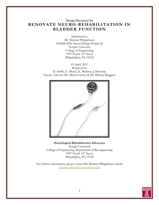
  • 8. 8 PROBLEM STATEMENT As mentioned previously, spinal cord injury and/or neurological disorders can result in the loss of bladder control and motor function. Neuroprosthetic devices have been developed with the intent of restoring motor function3 in individuals with paralysis due to SCI via functional electrical stimulation4 . Under normal conditions, the “brain and spinal cord control two main functions of the lower urinary tract: storage and periodic elimination of urine.” (Tai et al, 2006) After SCI, the voluntary control of the lower urinary tract5 is lost and thus force an individual to resort to treatment options that may be uncomfortable, dangerous or ineffective. Significant research has been conducted to establish efficient and effective surgical methods to restore function of a decentralized bladder after spinal cord or spinal root injury by focusing on the repair of the injured roots via nerve transferring methods and more. Several studies have concluded on certain strategies for bladder innervation and the corresponding effectiveness of each technique to restore urinary function (urinary continence6 and micturition7 ) after bladder decentralization. (Gomez-Amaya et al., 2015) Overall Objectives The first problem with the current Avery electrode design that we will be considering is its size. The electrode model currently in use has a fixed diameter, which is not ideal for nerve cuff designs because of potential nerve swelling due to invasive surgery. Many designs incorporate a diameter much larger than the nerve to compensate for this limitation, but this requires a higher level of stimulation for neuro-rehabilitation, which can produce adverse effects on the surrounding tissue: “In vivo8 biological tissues withstand moderate and repeated mechanical deformations to accommodate movements around joints. During traumatic injuries, neural tissues may experience violent mechanical stretch with strains of tens of percent.” (Lacour et al., 2010) Our design will resolve this limitation by utilizing shape memory alloys. These materials have a self- 3 Motor function: an umbrella term used to describe any activity or movement completed via the use of motor neurons. 4 Functional electrical stimulation: a technique that uses low energy electrical impulses to generate body movements 5 Lower urinary tract: made up of the bladder, internal sphincter, external sphincter and urethra. 6 Urinary continence: ability of the bladder to store urine. 7 Micturition: contraction of the walls of the bladder and relaxation of the trigone and urethral sphincter in response to a rise in pressure within the bladder; the reflex can be voluntarily inhibited 8 In vivo: performed or taking place inside a living organism. Figure 1: Avery cuff electrode
  • 9. 9 closing property that we think will be ideal for implantation. To take advantage of this property, we will be incorporating a nickel-titanium SMA (nitinol) layer in the nerve cuff that will allow the cuff to close upon a temperature stimulus, which is dependent on its specific material make-up. The purpose of this is to facilitate implantation, as the alloy will change shape specific temperature change, allowing for closure around the nerve. The hope is that this self-closing property will eliminate the need for external fixators to keep the cuff in place, such as sutures, and ultimately conquer the current difficulties of surgical implantation, a major limitation for generic nerve cuff electrodes (discussed in the proceeding section of the text). Additionally, the lead wire has limited flexibility, which can inflict nerve stress or even cause more strain on the platinum wire, causing breakage in some cases. To reduce nerve stress that might lead to breakage, we will design the lead wire with a coiled structure that is encapsulated in silicone tubing. This component of the electrodes design will permit strain relief on the attached electrode, a very desirable characteristic for nerve cuff electrodes. The Challenge of Interfacing to the Peripheral Nervous System The peripheral nervous system is responsible for relaying information to and from the brain/spinal cord to the extremities, mediating both “the instructions to the periphery for motor action as well as sensory feedback.” (Grill et al., 2009) Thus, damage to the PNS can result in partial or complete loss of function, including motor function of the lower urinary tract and bladder. Engineered devices for interfacing purposes, such as nerve cuff electrodes for rehabilitating a neurogenic bladder, inevitably create a list of challenges that can stem from several variables. Regarding our design objectives, biological challenges associated with the peripheral nerve are most important, as we intend to redesign an electrode that is far from optimal for the surgeon carrying out the implantation procedures and even the patient themselves. In short, the most limiting challenges for anyone designing, implanting, researching or requiring a nerve cuff electrode for the reinnervation of bladder function can be summed up by the following list published by a 2009 study conducted by Warren M. Grill and colleagues, (Grill et al., 2009): Challenge 1: selective9 stimulation of peripheral nerve fibers. In the peripheral nervous system, “the challenge of selectivity arises from two fundamental properties of nerve fiber stimulation: the current required for extracellular stimulation of axons depends first on the distance between the electrode and the nerve fiber, and second, the diameter of the nerve fiber.” Challenge 2: device and signal stability. Electrodes that penetrate mammalian neurons typically experience many potential sources of noise in and around the peripheral nervous system. As a result, fibrotic response recording capabilities around the electrode can worsen over time, and eventually initiate a buildup of fibrotic connective tissue that can completely cover the implanted device. Such a response almost always results in an ineffective device, ultimately requiring removal and/or replacement. 9 Selectivity: refers to the ability to activate one population of neurons without concurrent activation of another, neighboring population of neurons. (Grill et al., 2009)
  • 10. 10 Challenge 3: implant-induced injury and adverse consequences. Despite operative precautions that are typically taken for in vivo procedures, implants can still cause damage to the targeted nerve and/or surrounding tissues during insertion or after extended time in the body. This damage can lead to a loss of myelin, which could impede nerve conduction and therefore function. The nervous system is highly complex, and the nerves, fibers and blood vessels innervating the lower urinary tract alone are countless. Thus, surgically navigating through this field requires skill and precision, a task that even some of the best surgeons can fall short of. On top of this, attempting to implant and fixate a nerve cuff on a nerve as small as 1.5 mm in diameter can be nearly impossible. Even when surgical implantation is a success, lengthy operating times can introduce another entire realm of problems. Research has shown that long operating times, specifically to the lower urinary tract, can lead to infections and renal failure, thus highlighting the dire need to redesign commonly accepted electrode models for the successful treatment and rehabilitation of neurogenic bladders10 . Our main objective is to overcome the challenges mentioned above by fabricating a nerve cuff electrode that limits all possibility for and failure. This design will highlight an SMAs ability to self- close on a nerve upon a temperature change which will ensure proper fit and fixation on the nerve, significantly reducing operative time, limiting adverse consequences from invasive surgery, and reliably maintain position in the body, despite subjection to voluntary and involuntary movement. Economic and Historical Perspectives Spinal Cord Injury and Bladder Incontinence The lower urinary tract has two distinct functions, “the storage and periodic expulsion of urine, which are regulated by a complex neural control system in the brain and lumbosacral spinal cord.” (de Groat et al., 2006) The storage of urine “occurs at low pressure, which implies that the bladder relaxes during the filling phase.” (Andersson et al., 2004) On the other hand, emptying of the bladder “requires a coordinated contraction of the bladder and relaxation of the urethra.” (Andersson et al., 2004) For a complete summary of the nerves innervating the lower urinary tract, see, see figure 2. In addition, table 1 summarizes the reflexes associated with the lower urinary tract. Under normal condition, the bladder and its outlet exhibit a reciprocal relationship. For the proper storage of urine, “the pressure in the proximal urethral must be higher than the pressure in the 10 Neurogenic bladder: a problem in which a person lacks bladder control due to neurologic damage to either the brain, spinal cord or both. Figure 2: Innervation of the lower urinary tract. (Kanai et al., 2011)
  • 11. 11 bladder to prevent urinary incontinence.” (Stoffel et al., 2016) However, when the spinal cord experiences injury above the lumbar level, the trauma eliminates the reciprocal relationship between the detrusor muscle11 and urethral sphincter, causing simultaneous contractions. This process “generates high bladder pressure, prevents complete elimination of urine, requires daily catheterization,” and sometimes results in total renal failure12 . (Tai et al., 2006) Spinal cord injuries that disrupt normal micturition13 and cause simultaneous contraction of the detrusor and urethral sphincter can cause many side effects, ranging from an inability to eliminate urine to total renal failure. This simultaneous contraction generates high bladder pressure, which can cause “vesicoureteral reflux14 and renal failure in the long-term. Residual urine in bladder and urethral catheterization cause cystitis and infection,” (Tai et al., 2006) not to mention physical and emotional pain. Additionally, the disruption of micturition “causes a low bladder storage capacity and transient high intravascular pressure resulting in incontinence, risk for kidney damage and bladder hypertrophy.” (Tai et al., 2006) Table 1: Reflexes to the lower urinary tract. (Groat et al., 2006) After spinal cord injury, the external urethral sphincter15 (EUS), innervated by the pudendal nerve16 , loses all its voluntary17 ability to contract or relax. Due to the mechanism of innervation, stimulation 11 Detrusor muscle: bundles of smooth muscle fibers lining the wall of the urinary bladder; serve to expel urine. 12 Renal failure: a medical condition characterizing impaired kidneys that fail to adequately filter and remove metabolic waste from the body. 13 Micturition: the act of passing urine; physiological processes of the bladder in which the walls of the bladder contract while the trigone and ureteral sphincter relax in response to a rise in pressure (Tai et al., 2006) 14 Vesicoureteral reflux: the backward flow of urine from the bladder into the kidneys 15 Urethral sphincter: a muscular mechanism that controls the retention and release of urine from the bladder 16 Pudendal nerve: a somatic nerve in the pelvic region that originates from the sacral spinal cord; the pudendal nerve becomes excited as the bladder fills; stimulation of the pudendal nerve results in contraction of the external urethral sphincter. 17 Voluntary: done in accordance with the conscious will of the person; operated by the somatic nervous system
  • 12. 12 of the pudendal nerve by a neuroprostheses holds the potential to control the activity of the EUS, and thus provide the support needed to regain functionality of the bladder. Figure 2 below outlines the subsequent events occurring in the lower urinary tract after SCI. First, injury to the spinal cord causes detrusor dyssynergia18 , leading to functional obstruction of the urethra. Increased urethral resistance then induces bladder hypertrophy19 , resulting in increased levels of NGF in the bladder smooth muscle. The increased NGF in the bladder and spinal cord is then transported to bladder afferent pathways20 , which in turn become hyper-excited. The hyper-excitability of these afferent pathways induce neurogenic detrusor over-activity. (de Groat et al., 2006) Figure 3: Diagram of hypothetical mechanisms inducing lower urinary tract dysfunction following spinal cord injury. (de Groat et al., 2006) Neuroprostheses Neuroprostheses are devices “that use electrodes to interface with the nervous system and aim to restore function that has been lost due to spinal cord injury.” (Collinger et al., 2013) They carry the potential to restore motor, sensory and autonomic functions through the stimulation of muscles, nerves, spinal cord or even the brain. Most neuroprostheses function as a neural interface between an external stimulator and the nervous system. Neuroprostheses classify a wide range of medical devices and systems, the most common being nerve cuff electrodes. Electrodes intended for rehabilitation purposes are made with microelectrode arrays (MEAs), designed specifically for monitoring and/or stimulating extracellular neuronal. However, designing neural electrodes can be a challenge due to the biomechanical and structural mismatch between current MEAs and neural tissues. Currently, there are four different types of MEAs for neural interfaces, each encompassing their own unique strengths and limitations. These arrays are micro-fabricated using technology and stiff materials, and usually produce rigid structures or materials that are not always ideal for their 18 Detrusor sphincter dyssynergia (DSD): the urodynamic description of bladder outlet obstruction from detrusor muscle contraction (Stoffel et al., 2016) 19 Hypertrophy: increase in volume of a tissue or organ produced entirely by enlargement of existing cells. 20 Afferent pathway: the route taken, usually by a linkage of neurons, from the periphery of the body toward the central nervous system
  • 13. 13 intended application. Research focused on the biomechanics of cells has documented that cells can be extremely sensitive to any change in the mechanical properties of their surroundings, so by introducing a stiff, man-made device to a nerve in vivo inevitably produces an adverse effect (see figure 1). In general, “implanted electrodes trigger a foreign body reaction leading to chronic inflammation and scar formation,” (Lacour et al., 2010) thus highlighting the difficulty in designing an effective neural electrode for rehabilitation purposes. The design of an electrode array falls into one of the following categories: plantar, penetrating, regenerating, and cuff electrodes. Plantar electrodes are characterized by metallic patterns on glass, silicone and other polyimide substrates, and are designed for extracellular stimulation/recording in vivo. These electrodes are flawed in their structural composition since they are very rigid and thus cannot monitor neuronal activity from tissues or cells subjected to mechanical deformation or injury, making this array less than ideal for our application. The second type of array is the penetrating electrode, which are fabricated with silicone or titanium and based on needle-like structures that are penetrated the brain or a nerve in vivo. The flaw with these electrodes is that they are not reliable for stable and long-term recording and/or stimulation because the electrode is too stiff and thus can be negatively impacted by in vivo cellular reactive response and tissue-electrode impedance, highlighting why this array will also not be used for our project design. The third array is the regenerating electrode which primarily function as devices that are inserted into the proximal stump of a sectioned nerve to provide a structure that allows for the nerve fibers outgrowth. This array will also not be implemented in our design because of its unreliability for long-term applications. (Hoffer et al., 1990) The fourth and final array, and the one that will be used for our design is the cuff electrode. These neuroprostheses are designed to restore motor function by applying electrical stimulation to the paralyzed nerve. This is targeted towards individuals with neurological disorders and/or have experiences spinal cord injury by applying electrical stimulation to the paralyzed muscles. Nerve cuff electrodes are characterized by their ability to wrap around a peripheral nerve21 before reaching a muscle to activate all innervating muscle fibers to that specific nerve. This makes them ideal devices to deliver electrical stimulation to muscles that are deep or otherwise represent difficult surgical targets. (Blana et al., 2013) Research has even proven that they are one of the most reliable and effective neuroprostheses for rehabilitation purposes, as it has been said that they are a “principle tool of basic and applied electro-neurophysiology studies and are championed for their ability to achieve good nerve recruitment with low thresholds.” (Foldes et al., 2011) Functional Electrical Stimulation (FES) FES has become a widely adapted method for effectively restoring lower urinary tract function in individuals with bladder incontinence due to SCI. This method of stimulation involves the activation of the bladder and inhibition of the urethral sphincter to produce voiding, or the inhibition of the bladder to provide urinary continence. (Ho et al., 2014) One of the first clinical methods for neuro- rehabilitation utilizing FES came from the Brindley approach, which induced bladder contractions by delivering repeated bursts of stimulation to bladder motor efferent in the sacral roots. However, one of the major flaws with this approach is that it “requires transection of the dorsal spinal roots to 21 Peripheral nerves: nerves that form a network of pathways for sending and receiving information throughout the body.
  • 14. 14 eliminate unwanted bladder and urethral reflexes due to sensory feedback,” (Ho et al., 2014) thus attributing to the development of other approaches for treating bladder incontinence. It is important to note that our final product will become functional as a neuro-rehabilitation device through the use and application of FES to the pudendal nerve. In general, FES describes “the use of electrical stimulation in excitable tissue to supplement or replace functions that have been lost in neurological injuries and assist or substitute an individual’s voluntary ability.” (Gomez-Amaya et al., 2015) This method of stimulation will be applied, transmitted through the lead wires, retrieved by the platinum contacts embedded on the cuff wall and ultimately delivered to the nerve itself. The following statement provides a brief synopsis of the physiological processes and mechanisms resulting from FES that are essentially responsible for the level of neuro-rehabilitation required to restore bladder function: “A localized electric field is established, which depolarizes22 the cell membranes of adjacent nerves, followed by an increased influx of extracellular sodium ions into the intracellular space generating action potentials. To generate muscle contraction, the stimulus must be applied along the length of the peripheral nerve, but not to the muscle itself. The number of nerve fibers that become activated and the force of the muscle contraction is determined by the strength of the electrical stimulus (amplitude and duration).” (Gomez-Amaya et al., 2015) Shape Memory Alloys (SMAs) Shape memory alloys (SMAs) are essentially metals that can return to a former shape when subjected to a thermomechanical procedure, such as a heat treatment. SMAs composed of nickel and titanium are known as nitinol, and have become one of the most popular SMAs for clinical use, and will be the alloy implemented in our project design. Although nickel alone is extremely toxic to the human body, Nitinol forms a passive titanium oxide later that acts as both a physical barrier to nickel oxidation and protects the bulk material from corrosion, classifying it as safe and biocompatible. Nitinol alloys are “cheaper to produce, easier and safer to handle, and have better mechanical properties compared to other existing SMAs.” (Jani et al., 2014) Nerve cuff electrodes are notorious for being extremely difficult to surgically implant due to the size and location of different nerves in the human body. To compensate for this difficulty, a new nerve cuff electrode with shape memory armature is presented. Shape memory alloys ensure the complete and firm closure of the electrode around the nerve due to a self-closing property of the alloy under certain temperature thresholds after being heat treated. Research has concluded that the complexity of the instillation procedure is considerable reduced, as the SMA component of the electrode eliminated the need for external fixation such as sutures to keep the electrode in place and secure permanent contact of the electrode on the nerve. (Crampon et al., 2002) Design Concept Candidate Solutions One of the first recognized solutions to bladder incontinence dates to 1917 where “the use of massage to empty a distended bladder” was implemented for the first time in France. (Cho et al., 22 Depolarize: the reduction of a membranes resting potential so that it becomes less negative.
  • 15. 15 2012) This solution led to over distension of the bladder23 , where the bladder began to swell from high internal pressure (Cho et al., 2012). Another manual method of urine extraction is characterized by positioning one hand on the top of the uterus and then squeezing it between the thumbs and remaining fingers, called Crede Manoeuvre (Pena-Marti et al., 2007). The intermittent catheterization (IC)24 was then developed (Cho et al., 2012), as a method that focused on averting high residual volumes to lower the risk of potential UTI (Clarke et al., 2005). However, intermittent bladder catheterization had an “increased danger of inflection caused by urethral manipulation” in addition to over distension of the bladder (Cho et al., 2012). Another option of IC, that is not a long-term treatment option is called clean technique IC (Cho et al., 2012). Individuals who utilities the clean technique IC “require restriction of fluid intake so that catheterization only has to be performed a maximum of every 4 hours” (Cho et al., 2012). Unfortunately, the complications associated with this type of treatment option range from the bladder neck being traumatized or urethral bleeding and bacteremia from forcible catheterization (Cho et al., 2012). Percutaneous Radiofrequency (RF) Sacral Rhizotomy25 is another minimally invasive treatment option designed to increase the clean intermittent catheterization volume (Gomez-Amaya et al., 2015: “RF ablate the nerve by generating heat around the nerve tissue using high frequency waves, resulting in a denaturation26 of protein in nerve fibers” (Cho et al., 2012). This method “reduces the pressure of the detrusor muscle and increases bladder volume” (Cho et al., 2012), and improves the efficiency of bladder emptying all while reducing the risk of secondary URI and/or damage to the upper urinary tract that could be fatal. (Gomez-Amaya et al., 2015) However, limitations to this type of treatment option include the time duration required for the injured nerve to recover, added to the fact that the long-term effects of RF remain unknown. (Cho et al., 2012) The Finetech-Brindely FES system is the most documented treatment option for bladder incontinence, which is used to “stimulate the cord region that contains the micturition center generating not only contraction of the detrusor muscle, but also contraction of the urethral sphincter, in turn increasing outflow resistance while inhibiting voiding” (Gomez-Amaya et al., 2015). Dr. Michael Ruggieri implements this system on female mongrel hounds, “to determine whether transfer of a primarily motor nerve (Femoral, F) to the anterior vesicle branch of the pelvic nerve (PN) allows more effective bladder reinnervation than a primarily sensory nerve (genitofemoral, GF).” (Gomez-Amaya et al., 2015) However, this approach comes with its limitations as well: There is significant scare tissue that forms around the nerve cuff placement which is attributed to the movement of the bladder emptying and filling (Gomez-Amaya et al., 2015). 23 Bladder distension: a medical condition in which the bladder is stretched; usually a side effect os urinary retention. 24 Intermittent catheterization: the insertion and removal of a catheter several times a day to empty the bladder. (Newman et al., 2011) 25 Radiofrequency (RF) rhizotomy: a therapeutic procedure designed to decrease and/or eliminate pain symptoms arising from degenerative facet joints within the spine. 26 Denaturation: the alteration of a protein shape through some form of external stress; this alteration in shape will eliminate the cells ability to carry out its cellular functions.
  • 16. 16 Proposed Solution To address the limitations of the current Avery breathing pacemaker electrode, the optimum solution would be to integrate a shape memory alloy component within the nerve cuff. This will eliminate the need for sutures and reduce the surface area to decrease development of scare tissue. Furthermore, the shape memory alloy is also compliant to the fluctuating diameter of the nerve during and after surgery based on its self-closing properties. By eliminating sutures, this will also decrease the time the surgeon is operating which will lower the risk for infection. To decrease the stress/strain on the nerve cuff the wire leads will be coiled to allow for greater flexibility within the body. Additionally, surgical implantation will involve placing the lead wires percutaneously, which increases their tendency to shift overtime as a direct result of patient movement. Studies have shown that once these lead wires move away from the nerve, the patient no longer experiences sensory stimulation and thus the benefits of neuromodulation are essentially eliminated. However, our proposal introduces the idea of coiling these wires to decrease the problems associated movement. The hope is that the coiled wires will be able to withstand much more stress than uncoiled wires, and ultimately remain in place due to their ability to compensate for the normal physiological movement of the lower urinary tract. Major Design and Implementation Challenges Incorporating FES with various neuroprostheses can be a challenge due to the number of parameters that determine whether FES will execute a desired objective- in this case, the objective being to restore bladder function. The number of muscles targeted by an FES device (the nerve cuff electrode) is “a function not only of the level of injury, which determines the extent of the paralysis, but also the number of stimulating channels available in the neuroprostheses itself…it is the availability of stimulating channels and not the remaining motor function that limits the number of muscles targeted for FES.” (Blana et al., 2013) Furthermore, as the number of stimulating channels available increases, “the problem of determining which muscles to stimulate to restore the most function to a specific individual becomes difficult yet important for the success of the FES system.” (Blana et al., 2013) Fabricating our nerve cuff to restore the maximum amount of bladder reactivity depends highly on determining the targeted nerves (in our case, the pudendal nerve) level of response to electrical stimulation. However, this challenge was overcome by conducting extensive research on current neural reconstructive methods for restoring bladder function. Documented electromyography (EMG) results from such studies, like the works of Dr. Michael Ruggieri, allowed for the analysis of stimulation patterns elicited by FES which then allowed for the identification of the optimal nerve set for the level of spinal cord injury that resulted in loss of bladder function. One major limitation of our design deals with using an MEA that will contribute to our projects success. The biggest challenge in producing MEAs stems from the fact that once introduced to the body, they must minimally disrupt the cells environment so that they “(i) behave in vitro like in the body, (ii) they induce in vivo minimal inflammatory response, (iii) they provide long-term communication between neural fibers and electronic hardware, and (iv) when needed, they conform and deform along with the 3D neural tissue.” (Lacour et al., 2010) Additionally, cuff electrodes
  • 17. 17 should be fabricated with materials that minimize rigidity since a highly rigid material will not be able to sustain large deformations or will fail by mechanical fracture at small strains. Lastly, the SMA wire utilized in our design introduces a list of challenges. First, determining the appropriate heat treatment for our nitinol wire was extremely difficult, as the specific parameters chosen for the treatment highly influence the properties of the wire post heat treatment. Because we needed the wire to exhibit certain characteristics under very specific temperature thresholds, its associated parameters were very hard to determine with the limited experience we all have with shape memory alloys. Second, performing the actual heat treatment was another challenge, as we did not have access to any device capable of producing the rightly controlled extremely high temperatures needed. However, we overcame this issue in two ways: by (1) resorting to the help of a company specifically established to provide the type of heat treatment we required, and (2) familiarizing ourselves with a high temperature tabletop furnace manufactured for various applications requiring heat treatments up to 1650°C. Implications of Project Success While current methods of bladder relief including catheters, stents, and artificial sphincters are viable options, they also have potential for adverse side effects. These risks include urinary tract infection, urethral dilation, and urethral damage. We believe there are safer options for patients suffering from neurological disorder and/or spinal cord injuries. The proposed solution would tackle the issue of bladder relief without the added risk of health problems. The nerve cuff incorporating the shape memory nitinol wire will facilitate surgical implantation and fixate on the nerve without requiring sutures. This will therefore minimize implantation time and reduce the risk of possible infection. The coiled lead wires will permit maximum flexibility within the body without the risk of damage to internal tissue. Combining these approaches creates a nerve cuff electrode that can adequately stimulate the bladder nerves to relieve the bladder. While this technology may be invasive for the patient, it ultimately provides a safer method of restoring bladder function to the highest degree possible. We also believe this form of technology can be utilized for other disorders/injuries apart from the bladder. The adaptability of the shape memory alloy may allow for implantation in many different areas of the body and thus provide stimulation to damaged nerves. Once the in vivo testing is completed in both rat and canine models, we will be able to explore the ability of the nerve cuff electrode to operate in multiple areas of the body that include varying parameters such as nerve diameter and available space. Our goal would include going beyond animal models and utilizing the technology in humans to safely and effectively treat bladder dysfunction.
  • 18. 18 DESIGN REQUIREMENTS Target Specifications All materials that will be used for our design need to be biocompatible to prevent the induction of a toxic or necrotic response in adjacent tissue or even an immune response resulting from the foreignness of the device. Platinum is biocompatible, inert within the body, durable, electrically conductive, and radiopaque. Nickel-titanium shape memory alloys have good biocompatibility response when its nickel content is less than or equal to 50%. Stainless steel is non-toxic, whereas copper and silver are unacceptable materials as stimulation electrodes because they cause tissue necrosis even in the absence of a current. (Merrill et al., 2005) Overall Design The overall design of the electrode will include coiled lead wires and a nerve cuff incorporating nitinol wire. The leads include two stainless steel wires coiled in tandem encased in silastic tubing. We aimed for the coiled wires to have an outer diameter of 0.76 mm without the silastic tubing and 1.3 mm with the silastic tubing. The nitinol wire is a shape memory alloy, which allows for shape- and temperature-setting. By coiling the nitinol wire around a ceramic rod with a diameter similar to the pudendal nerve, the wire would be properly shape-set to fit the nerve. The wire would then be heat treated in order to have the following parameters: · Ability to be straightened in a 10ºC water bath · Remain straight when taken out of the cold bath into room temperature · Close completely to the proper shape-setting when placed in 37ºC (body temperature) water bath These parameters allow for the cuff to remain open while outside the body and then close around the nerve once introduced inside the body. The cuff will also incorporate two platinum contacts on each side instead of the platinum spanning the entire cuff. This reduces the possibility of the platinum becoming too brittle and breaking. Overall, the electrode will have a flexible design that ensures easy implantation and minimizes health risks.
  • 19. 19 Leads The stainless steel Cooner Wire AS633 is coiled to form a double helix, with an inner diameter of 0.25mm and an outer diameter of 0.76 mm. The coiled lead is then placed inside silastic tubing, which has been expanded by the Vertrel XSi. When the Vertrel XSi evaporates, the tubing contracts, creating a tight fit between the tubing and the lead. The final diameter of the lead will be approximately 1.3mm (Memberg et al., 1994). Figure 5: coiled wire encased in silastic tubing for insulation purposes Figure 4: stainless steel coiled wire
  • 20. 20 Figure 6: coiled wire dimensions
  • 21. 21 Nerve Cuff: Shape Memory Alloy The shape memory alloy comes into play at the final stage of the fabrication process, when the nerve cuff will be shaped for clinical application. Instead of curving the cuff in vitro27 , the SMA will self-curl the cuff around the nerve once introduced to the biological environment of 37 C in vivo, and form an inner diameter of the cuff corresponding to that of the targeted nerve. In terms of our design, the diameter of the cuff will depend on the cross- sectional area of the pudendal nerve trunk, the final location of the cuff upon successful implantation. Specific design parameters of the nerve cuff will include the (i) cuff shape, (ii) cuff size, (iii) total number of contacts on the cuff and (iv) contact orientation. However, prior to fabricating our enhanced nerve cuff with the nitinol alloy, we first familiarized ourselves with the processes involved in fabricating the nerve cuff currently in use at the medical research facility at Temple University Hospital. This was a necessary step in our product development process before tackling the approach to fabricate our final design because it allowed us to understand all components and design aspects that are flawed with the current model. Figure 7 is the final product of the nerve cuff after manufacturing it in the lab. Figure 9: fabricating the nerve cuff that we intend to redesign due to its major flaws and limitations. 27 In vitro: performed or taking place outside of a living organism (for example, in a test tube or culture dish) Figure 7: Sample nerve cuff fabricated in the lab Figure 8: Platinum contact configuration for the Avery electrode.
  • 22. 22 SMA Shape Setting28 29 30 For a shape memory alloy to reveal its shape memory effect31 properties, the alloy must undergo a shape setting treatment. Shape setting “is accomplished by deforming an SMA part to a specified shape and constraining the configuration followed by appropriate heat treatments.” (Heidari et al., 2016) These types of materials exhibit a phenomenon that are “influenced by their chemical composition, fabrication method, and post heat treatments, a combination of cold work and annealing32 at specific temperatures that is comprehensively considered to improve the characteristics of a SMA.” (Heidari et al., 2016) The shape memory effect is a unique effect that attracted us to this material in the first place. This effect is produced what is known as the crystalline phase change (martensitic transformation) (Abregast et al., 1992). This martensitic transformation happens over a wide range of temperatures (Abregast et al., 1992). The memory shape is termed austenitic (Abregast et al., 1992). To change from austenitic to martensitic the material must be cooled and a shear stress must be applied (Abregast et al., 1992). If there is no stress that is applied during the cooling phase there will be no shape change will occur (the 10 degree Celsius bath) (Abregast et al., 1992). The material will hold this deformed shape indefinitely as long as it is being held below the desired transformation temperature (Abregast et al., 28 Martensite: the daughter phase of Nitinol; low temperature phase. When an SMA is in martensite form, the metal can be easily deformed into any shape. (“Nitinol Glossary,” n.d.) 29 Mf : martensite final temperature (“Nitinol Glossary,” n.d.) 30 Austenite: the parent phase of nitinol; high temperature phase. In the austenite phase, the SMA “remembers” the shape it had before it was deformed. (“Nitinol Glossary,” n.d.) 31 Shape memory effect: describes the process of restoring the original shape of a plastically deformed shape memory sample by heating it. (“Nitinol Glossary,” n.d.) 32 Annealing: a heat treatment that alters a material by changing properties like hardness and strength. (“Nitinol Glossary,” n.d.) Figure 8: Diagram of the Shape Memory Alloy Properties Graph 1: Effect of annealing temperature on the transformation temperatures. (Heidari et al., 2016)
  • 23. 23 1992). Once the material is heated (body temperature) it will return to its austenitic form, refer to Figure below (Abregast et al., 1992). With each phase of the crystalline phase change the nitinol during the austenite has a coefficient of thermal expansion of 11.0E-6/deg.C. The martensitie phase as a coefficient of thermal expansion of 6.6E-6/deg.C. These values are very insignificant and will not have a noteworthy impact on the nerve cuff when implanted in the body. A detailed approach on shape setting our specific wire will be discussed in a later section, but executing that process required us to determine the temperature at which the heat treatment would occur, and its duration. Due to our specific application, our nitinol wire needed to exhibit a transformation temperature of roughly 35℃. For SMA wire to execute its function of self-closing the nerve cuff around a nerve, it needed to exhibit a property in which the wire would return to the shape set for its heat treatment once introduced to a temperature stimulus that closely mimics that of the body. After conducting extensive research on shape setting nitinol, and referencing to graph 1 above, we infer the nitinol needs to be heat-treated around 490℃ for roughly 90 minutes, followed by a cold-water quench. Final Specifications Figure 10: Preliminary design of the nerve cuff with all components. Figure 11: Preliminary design of coiled lead wires; Two stainless steel wires helically wound and inserted into silastic tubing (Memberg et al., 1994)
  • 24. 24 Upon introducing anything man-made into the body, you will inevitable produce a foreign-body response, which typically induces encapsulation of the body by surrounding tissues. These responses are a function of both the chemical compatibility (or its inert surface properties), and the mechanical compatibility of the implanted material. (Machado et al., 2003) Subsequently, the more compatible the material, the thinner the encapsulation later, so in creating our cuff design, we needed to ensure that all materials were as biologically compatible as possible. In general, the biocompatibility of a material is “strongly related to allergic reactions between the material surface and the inflammatory response of the host.” (Machado et al., 2003) The overall design of the cuff will closely mimic that of a self-sizing spiral nerve cuff electrode due to the implementation of the shape memory wire. In general, self-sizing spiral electrodes limit mechanical damage and “have been shown to be suitable for long-term implantation in both animals and in man.” (Vince et al., 2004) Building these types of electrodes usually consists of inserting platinum dot contacts welded to stainless steel wire leads between two sheets of silicone rubber with windows cut out. The difference between generic spiral electrodes and the nerve cuff electrode design we will be implementing stems from eliminating the step in the fabrication process that requires one of the silicone sheets to be stretched before bonding the two sheets together with a silicone elastomer. (Vince et al., 2004) This step would have created the self-curling spiral property of self-sizing spiral nerve cuff electrodes, and is not required for the fabrication of our SMA nerve cuff. In terms of stimulation requirements, the precise position of the nerve cuff on the nerve itself is highly important. Essentially, we need to position the electrical interface as close to the neural tissue as possible for the cuffs final placement on the nerve, to limit the level of electrical stimulation required to activate the nerve. A lower stimulus threshold current will subsequently decrease the power demands on the external stimulator system, which will be idea. (Foldes et al., 2012)
  • 25. 25 Environmental Concerns Freon R134a: 1,1,1,2-Tetrafluoroethane (CH2FCF3) Vertrel Xsi: 20mL Compound ODP* GWP** Value GWP Rating Extra notes Freon (R134a) 0 1430 Medium Safety: A1 Vertrel Xsi 0 741 Low Accepted by EPA under Significant New Alternatives Policy (SNAP) as substitute for ozone depleting substances; exempted as volatile organic compound*** The Freon (R134a) was initially utilized to place the coiled wires into the silastic tubing. It was shown to evaporate too quickly, so Vertrel XSi was used for this purpose instead. Both compounds have an Ozone Depleting Potential (ODP) of 0, but the Vertrel XSi has a lower Global Warming Potential (GWP) of 741 compared to that of the Freon at 1430. The Vertrel XSi is also accepted by the EPA under the Significant New Alternatives Policy (SNAP) as a substitute for ozone depleting substances and is exempted as a volatile organic compound. While the Vertrel is “better” for the environment compared to the Freon, both substances were used under a fume hood. *Ozone depleting potential: Relative amount of degradation to the ozone layer a chemical compound can cause; ratio of global loss of ozone due to given substance over the global loss of ozone due to CFC-11 of the same mass **Global warming potential: relative measure of how much heat a greenhouse gas traps in the atmosphere; compares amount of heat trapped by a certain mass of the gas to the amount of heat trapped by a similar mass of carbon dioxide (GWP = 1) ***Organic compounds that easily become vapors or gases Plexiglass Plexiglass was utilized because it was readily available, cheap, and east to cut/mold. It was also used to be able to see the R-124a/Vertrel Xsi when encasing the leads into the silicon tubing. We chose to utilize Plexiglass because it has the ability to be broken down to its original chemical compounds and recycled. In addition to being entirely recyclable Plexiglass is hormone-free and metal-free. It is produced with all economic and environmental concerns satisfied.
  • 26. 26 APPROACH Lead Design The Avery breathing pacemaker currently includes lead wires that are straight and prone to breakage/splintering. Our solution to this problem was to redesign the lead wires with a coiled configuration followed by encasement in silastic tubing. The motivation behind the coiled design included flexibility within the body without the risk of internal damage to both the wire and body tissues. When coiling the wires, the desired dimensions included an inner diameter of 0.25 mm and an outer diameter of 0.76 mm (Memberg et al., 1994). Within the silastic tubing, we aimed for an outer diameter of 1.3 mm (Memberg et al., 1994). The stainless-steel wire utilized was Cooner wire AS633 was coated with PTFE- a stainless steel wire with a polymer coating to reduce the number of potential corrosion sites throughout the wire. Corrosion can occur from the effects of charged voltages supplying the FES. The stainless-steel wires were coiled utilizing a hand drill. A second PTFE-coated stainless steel wire was clamped inside the hand drill. The PTFE-coated wire had an outer diameter of 0.25 mm. Two AS633 wires of the same length were taped to the base of the drill and simultaneously wound around the PTFE-coated wire. The total length of the coiled wires was 15 inches. The two wires were coiled in tandem apart from one end of the total coil. The two wires were separated at this end and utilized as the points of contact on the nerve cuff. Once the coiling was completed, the coiled wires were encased in silastic tubing. This was accomplished by using Vertrel XSi. First, a shallow groove was drilled into a piece of plexiglass with length of 24 inches as shown in figure 11. This shallow groove allowed for the full length of silastic tubing to be submerged in the Vertrel XSi all at once. Figure 12: Set up of creating the shallow groove in the plexiglass.
  • 27. 27 When submerged in Vertrel XSi, the silastic tubing expanded. This allowed for the placement of the coil inside of the tubing. The silastic tubing was completely submerged in 20mL millileters of Vertrel XSi for a 20 seconds duration. The tubing was then taken out of the Vertrel, and the coiled wires were placed inside. The evaporation of the Vertrel XSi caused the tubing to shrink back down to its original size and created a tight fit around the coiled leads. Figure 14: Placing the coiled lead wire inside of the expanded silastic tubing using forceps. Figure 13: Final piece of plexiglass with shallow groove.
  • 28. 28 Shape Setting: Heat Treatment To use the nitinol wire as intended for our application, it must first undergo a heat treatment regimen required for shape setting the material. In the case of our application, we needed the nitinol to exhibit its shape memory effect at a transformation temperature of roughly 37℃ (the temperature of the human body). To do this, its shape setting process required a heat treatment of the alloy while being restrained in a shape that closely mimics that of the nerve diameter, at a specific annealing temperature. Figure 16 shows our nitinol alloy wrapped around and fixed to a ceramic rod that is a close comparison in size to the pudendal nerve. We needed to restrain the wire in this shape so that post heat treatment, and upon introduction to the biological environment, the wire would conform to a cylindrical shape and essentially wrap itself and the entire nerve cuff around the nerve (once the cuff is successfully fabricated). Due to a lack of research on shape setting Nitinol, the methods which we took for each heat treatment was slightly sporadic. We knew that the parameters which would produce a successful outcome post heat treatment were highly dependent a sensitive to the time duration of the treatment and the treatment temperature. Initially, we chose to fix our nitinol wire to a ceramic rod (diameter: 0.0625” or 1.5875 mm)(figure 15) by utilizing high temperature cement glue, and then send out the configuration to from Accurate Thermal Systems, a company that offers nitinol shape setting and heat treatment procedures in fluidized temperature baths. Specific parameters of this heat treatment are listed in table 3 below. Upon receiving our nitinol wire post heat treatment, and testing it in various cold water baths, ranging from 5℃ to 15℃, we concurred that this specific heat treatment was not a success regarding its intended Figure 17: opening Nitinol ring in 10℃ water-bath. Figure 16: Nitinol ring closing completely once taken to ambient (room) temperature. Figure 15: Nitinol wire wrapped around a ceramic rod of similar size to the pudendal nerve, and restrained in this fashion prior to/during heat treatment.
  • 29. 29 application. This was determined by the fact that a successful heat treatment would allow for easy opening of the individual nitinol rings in a cold-water bath, their remaining in that open position once removed from the ice bath and taken to room temperature, and finally their rapid closing back to a congruent circular shape once introduced to a 25-35℃ water bath (an environment mimicking that of the body). This heat treatment allowed for easy opening of the rings in the cold-water bath, but upon transition to ambient, room temperature, the rings closed rapidly and could not be opened again until back in the cold environment. Table 3: Accuthermal heat treatment table Wire # C1 T1 C2 T2 C3 T3 C4 T4 D 0 500 5 0.006 1 95 5 914 5 94 -121 0.004 2 50 5 900 5 50 -121 0.004 3 71 5 900 90 914 5 71 -121 0.004 4 71 5 900 90 914 5 71 -121 0.006 Table 4: Temperature Activation table Wire # Cold Water Bath (Celsius) Time of submersion (min) Annealing Temp. 1 3 5 Ambient 2 10 Ambient 3 10 5 30 Note: In the Table 3 there are 4 wires that are being heat-treated. C1 is the first temperature that is set for wires 1-4 and it symbolize ambient temperature. T1 is the rate of rise, which is constant throughout testing. C2 is the desired heat treatment temperature, which corresponds to the time of heat treatment in minutes. In wires one and two C3 is ambient temperature, while wires three and four the temperature increases and decreases to ambient temperature at T4. T3 for wires one and two are stopping temperatures while wires three and four is the rate of rise and have stopping temperatures at T4. There are two different diameters (inches). In Table 4 demonstrates the values during the temperature activation test. First the wire is placed in the cold-water bath with different submersion times then placed in the annealing temperature of either ambient temperature or 30 degrees Celsius. The first wire closed right away at body temperature, but also closed slowly at room temperature; did not remain open at annealing temperature. Wire three stayed open at ambient temperature, opened easily at 10 degrees Celsius and closed right away at 30 degrees Celsius. Once we definitively determined that the first batch of wire subjected to a heat treatment was unsuccessful, we familiarized ourselves with the Rapid-fire Pro Tabletop Furnace (Table 3 -4) available to us through Temple University’s Bioengineering Lab within the College of Engineering. Thoroughly understanding the furnace and how to use it came after extensive research and long phone calls with the Tabletop Furnace Company stationed in Tacoma, Washington. The following list provides a detailed description on the systems programming requirements, and our methods for success (after numerous failed attempts).
  • 30. 30 Step 1: Turn furnace on Once the furnace is on, numbers and text will appear on the programmer. All numbers have units of °F and/or minutes. Step 2: Record ambient temperature In the window to the left of marker number 2, a red number will appear. This value is your ambient temperature, corresponding to the ‘C1” value you will enter once prompted. Step 3: Press button ‘A/M’ to start programming When ready to program, the window right below marker number 2 will flash with the word ‘HOLD’. This means it is ready for you to enter the parameters for heat treatment. Step 4: Enter heat treatment parameters (most confusing step in the programming process) At this step, you will be prompted to enter in different values in which the system labels the entered parameters as denoted by C(1-30) and t(1-30) 1. The first value the program asks for is C1; this corresponds to the ambient temperature you recorded in step 2. Once entered, press ‘Set’ button directly to the right of marker number 4 2. Next, you will be prompted to enter t1; this is your rate of rise to the next desired temperature. For our heat treatment, we chose t1 to be 5 minutes. Follow this by pressing ‘Set’ to the right of marker number 4 3. The next prompt will be to enter C2 followed by ‘Set’; this is your start temperature for the heat treatment. In our case, C2 = 900°F (or 482°C) 4. The following prompt is for t2; t2 corresponds to the time duration for your heat treatment. Our t2 = 90 minutes. Follow your entry by pressing ‘Set’
  • 31. 31 5. Next, enter C3; this is the maximum temperature you want the heat treatment to reach at the end of the 90 minutes, programmed in the previous step for t2. Here, C3 = 914°F (or 490°C) 6. Lastly, you will be prompted to enter t3; since you programmed all necessary parameters for the heat treatment, t3 will give the command to STOP; to do so, you will use the universal STOP code given by the company as -121. Step 5: Run your heat treatment After all your parameters are programmed correctly, wait a couple of seconds for the screen to return to its initial state, where ‘HOLD’ is flashing in the window just below marker number 2; now find the down arrow button, marked by number 5, and hold that down for roughly 3-5 seconds. This will prompt ‘run’ to appear on the program window. - Your heat treatment will begin in a couple of seconds. First, the furnace will heat up from ambient temperature to 900°F. Once the furnace reaches this value, open the furnace door using heat safety gloves, and place your wire inside. Once you lock the door, you reached the waiting stage in the process- your wire will cook for 90 minutes, until the program reaches 914°F (figure 19). Step 6: Cold water quench At 914°F, open the furnace, take out your wire, and immediately drop your wire into a prepared cold water bath of 10°C (figure 18) leave it in the bath until the rod cools enough to touch. You’re finished! Figure 19: Final minutes of heat treatment. Figure 18: Immediate cold-water quench post heat treatment.
  • 32. 32 Nerve Cuff Fabrication Fabricating a nerve cuff electrode that will reliably deliver constant and predictable stimulation to the targeted nerve required its design to provide a stable and robust interface between electrode and nerve. (Foldes et al., 2012) One aspect of our design that will prove to provide this will come from the incorporation of nitinol embedded within the inner wall of the cuff (see figure 15 below). Figure 20: SMA armature made of NiTi split rings embedded in a thin silastic sheet. The geometric dimensions and design of the nerve cuff were established by assessing the size of the pudendal nerve, with the help of literature, and our targeted anatomical implantation site. Once these dimensions were established, we used them as a guide for the ceramic rod required for the nitinol shape setting process; this rod needed to mimic the dimensions of the pudendal nerve as closely as possible. Additionally, the final physical length of the cuff was limited by the anatomical implantation site but essentially was a product of our desired size for the electrode contact surfaces. Determining the precise size of electrode contact surfaces was selected to achieve the maximum estimated stimulus current required for our application. The thickness of the final cuff design was also constrained by the thickness of the silicone sheet that would form the structural backbone for the nerve cuff. Our specific electrode fabrication process will consist of the following steps, once we establish proper functionality of the nitinol post heat treatment. Step 1: Prepare silicone sheet for platinum contacts—Taking one of our silicone sheets, we will need to cut windows out that match the dimensions of the platinum contacts. These windows will be the final location for our electrode contacts, which will ultimately be in direct contact with the targeted nerve. This step will also include cutting the silicone sheet to our desired cuff dimensions. Figure 22: Measuring out the dimensions of the silicone sheet for final application (5mm x 8mm) Figure 21: guide for final placement of platinum contacts on the silicone sheet.
  • 33. 33 Step 2: Spot weld leads to platinum contacts—Once our lead wires have been properly helixed and encased in Teflon to provide the necessary insulation, the de-insulated tip of the lead wire will be spot welded to its intended contact. Figure 23: platinum contacts spot welded to stainless steel lead wires before fixation on silastic sheet with super glue. Step 3: Platinum contact configuration—Once both platinum contacts are spot welded to the lead wires, the next step is to secure them to the previously cut silastic sheet, as this layer will provide the electrical stimulation to the nerve once the cuff is fully assembled. To fix the contacts to the silastic, we used an infinitesimally small amount of super glue on the side of the contact that the spot welding was performed. This face of the contact will then be placed directly on the silastic sheet, requiring us to hold the contacts in place with forceps until the superglue dries (approximately 2 minutes). Next, will be utilizing an additional silastic sheet, previously prepared with the same dimensions. We will spread a thin layer of silastic glue to one side of this sheet, and then carefully place the glued side directly on the silastic holding the contacts. To assure that the sheets will set properly as the silastic glue cures overnight, we will be placing a later of Teflon tape over the top of the newly configured layering to guarantee that the silastic sheets are congruently glued together and thus provide the support needed to secure the platinum contacts in place. Finally, after the silastic glue had time to cure, and all layers are firmly secured to each other, we need to cut out windows from the silastic layer for the platinum contacts to have direct contact with the nerve once implanted. To achieve this, we used a #11 blade to carefully cut out windows around the perimeter of the contacts, and then utilized precision forceps to remove the window from the configuration. This process was conducted under a high intensity microscope to assure precision.
  • 34. 34 Step 4: Incorporation of Nitinol wire—Once our SMA has been properly heat-treated, we fix a silicone sheet (width corresponding to the width of the SMA wire coiled onto the metal/ceramic rod) by coating the outside of the wire with silicone glue. We then wrapped the silicone sheet smoothly around the rod, as to assure all of the wire was encased by the silicone. We placed very small clamps on the silicone sheet to keep it in place on the Nitinol as the silicone glue dried overnight. The circumferential dimensions of the final cylindrical cuff will be designed to be a small percentage larger than the diameter of the targeted nerve to compensate for any potential nerve swelling associated with implantation as well as provide an additional degree of flexibility. Step 5: Use silastic glue to combine all layers of cuff fabricated individually in steps 1-4
  • 35. 35 EVALUATIONS AND TEST RESULTS Testing Methods Range of Force Test Knowing that there is a lot of movement within the lower urinary tract, the lead wires should be able to compensate for pulling force applied on the leads. By using the Instron, we will test the range of force of the lead wire. The amount of force (load) applied to the wire will equate to how much stress the wire can hold before denaturing or breaking (up to 500N). This will be done to the wire, and if the load is greater than the force associated with biological movement, the wire will then be coiled and tested again to determine if coiled lead wire can sustain the load. Corrosion Test To test corrosion, we will place three leads into a container of saline in a temperature-controlled water bath. The leads will be stimulated continuously for approximately 48-72 hours. The stimulation parameters will vary, since this is commonly thought to affect corrosion (Memberg et al., 1994). The implantable stimulator uses 0.5mA pulses. We will be testing varying current of 10, 5 and 1 mA. The pulse duration will be 100μsec. The constant frequency will be 50Hz, which is double the maximum stimulation frequency of 24Hz. When removing the leads from the saline, the electrodes will be cleaned with deionized water and will be examined using a Scanning Electron Microscope. Regarding the test for corrosion properties of NiTi SMAs, assessment requires evaluation of the material when submerged in aqueous solutions. Once submerged, electron transfers between the metal surface and electrolyte is initiated, which reveals key differences in potentials between the anodic and cathodic sites. A considerable amount of research has been conducted to characterize the corrosion behavior of NiTi by utilizing comparative testing strategies- all of which seem to conclude that most studies assess the corrosion behavior in vivo by potentiodynamic33 set-ups. (es-Souni et al., 2005) Table 2: Parameters that affect corrosion. (Es-Souni et al., 2005) The medium surrounding the metal The metals surface state (the amount it hinders ion leaching processes) pH Roughness: associated with processing and manufacturing Composition: in- homogeneities and/or residues from product finishing Temperature Geometry factors: sharp- angles, edged faces Applied stress: induces susceptibility to 𝑯+ attacks Chemical composition (any presence of 𝑪𝒍− , 𝑭− 𝒐𝒓 𝑶) 33 Potentiodynamic set-ups: experiments in which the sample is placed in a well-defined test solution where it is subjected to gradually increasing potential. This potential is measured against a reference electrode and the resultant current density is monitored and assessed as a function of the potential. A marked increase in current density implies sample damage by corrosion.
  • 36. 36 Temperature Activation Test After heat treating the Nitinol wire, we needed to assure the treatment was a success by subjecting the wire to various temperature environments while applying strain to open the rings a desired amount. Successful heat treatment is characterized by a wire ring opening easily in a 10°C bath, remaining in the open position when transferred to room temperature, and closing on introduction to a 20-35°C environment. Figure 25: Cuff submerged in 10°C water bath for roughly 3-5 minutes. Figure 24: Gina testing if cuff can open easily in cold-water bath.
  • 37. 37 Bubble Test When testing the unit, we will resort to another simple test to make sure it is functioning properly. The leads and nerve cuff will be placed in a bowl of saline, and stimulated with an electric current. If the leads and cuff are insulated properly, the stimulation will produce no observable changes to the saline, but if there is a hole somewhere in the unit, bubbles will escape and be visible in the saline. When the lead and cuff show no signs of leakage, we will then test the entire device for continuity by measuring pressure changes under different stimulation thresholds. These tests will reveal the proper mechanical functionality of our device. Self-Closing Test To test the self-closing mechanism of our fabricated nerve cuff, we used a wire that has the equivalent diameter to that of the pudendal nerve, 1.7 ± 0.45mm (Gustafson et al., 2005). The self- closing test will allow us to test the self-closing mechanism of the nerve cuff and compare it to that of the Avery nerve cuff electrode. In addition, we used a wire to suture on the Avery nerve cuff electrode for comparative purposes. This procedure clearly illustrated how intricate and time consuming implantation of this cuff is, and ultimately highlight all the strengths of our design. To demonstrate this, two separate video recordings of cuff fixation- one being the Avery design and the other being our nerve cuff electrode were recorded. This provided us with a direct comparison between the fixation time as well as techniques for each cuff. The comparative video of the self-closing test showed that the Avery Nerve Cuff Electrode (one minute) takes three times longer to implant than the SMA nerve cuff electrode (17 seconds). There were some limitations that we faced when executing the self-closing test. When the nerve cuff electrode was being assembled each layer of the device decreased the overall diameter and when testing the self-closing mechanism, the inner diameter of the cuff was too small. This will be taken into consideration when developing the next prototype. In Vivo Test The final stage of our product development will require in vivo testing in a rat, as it’s the first step required to ultimately use in clinical trials. To track the activity of our electrode when stimulation is activated, we will be exploiting a technique set up by our project coordinator, Michael Figure 26: Avery Nerve Cuff Electrode Figure 27: SMA Nerve Cuff Electrode
  • 38. 38 Ruggieri. With successful placement and stimulation, we will get voluntary contraction of the bladder and will be able to analyze this contraction via the contraction of the leg. When stimulation is on, this nerve split will allow us to create a positive control, in which the nerve supplying the leg will contract when stimulation is transmitted properly. If the leg muscle is being contracted, the bladder must also be contracting. Table 3: Criteria for animal models for testing. (Parsons et al., 2011) Criteria Reliability The model provides consistent results Face validity The model has a similar phenotype to the human condition its imitating Aetiological validity The model is derived from a cause known to trigger the condition in humans Predictive validity The model is able to predict clinical outcomes in humans
  • 39. 39 Testing Results Range of Force Test By using the Instron, the amount of force (load) applied to the wire determined how much stress the wire can hold before denaturing or breaking. In Graph 2, the strain of the coiled wire is ten times larger than the strain of the uncoiled wire. The coiled wire and the coiled wire embedded in silastic tubing both break at the same strain but the silastic tubing can withstand about double the strain before denaturing. The silastic tubing has a linear relationship. Notice that both the uncoiled and coiled wire are breaking at the same load (~1N), however the coiled wire allows for more strain. In this case, load is more relevant to us rather than stress because 1kgf or 1N is equivalent to 2.2lbf. It was determined that the coil embedded in silastic tubing would uphold the physiological movements associated with the lower urinary tract. Corrosion Test- Leads The three electrodes were stimulated at a frequency of 50 Hz with varying currents. A typical bladder takes about 21 seconds to void, five times per day (Yang 2013). This totals 1.75 minutes per day. The parameters for each electrode as well as the calculations for the stimulation of the electrodes are shown below: Electrode Start Date/Time End Date/Time Current Temperature 1 3/29 @ 12:20 PM 3/31 @ 12:46 PM 1 mA 38C 3 3/27 @ 1:02 PM 3/29 @ 12:18 PM 5 mA 38C 4 3/24 @ 3:15 PM 3/27 @ 1:01 PM 10 mA Room Temp. Graph 2: Load vs. strain of both stainless-steel coiled and uncoiled lead wires
  • 40. 40 *Constant frequency of 50 Hz Electrode 1: 60 minutes * 24 hours * 2 days = 2888 minutes of stimulation 2888 minutes/1.75minutes per day = 1650.3days of stimulation *Around normal physiological level (1-2 mA) Electrode 3: 60 minutes * 24 hours * 2 days = 2888 minutes of stimulation 2888 minutes/1.75minutes per day = 1650.3 days of stimulation *2.5x-5x maximum physiological level Electrode 4: 60 minutes * 24 hours * 3 days = 4320 minutes of stimulation 4320 minutes / 1.75minutes per day = 2468.6 days of stimulation *5x-10x maximum physiological level No corrosion of any type was observed in any of the leads under the Scanning Electron Microscope. When comparing the energy-dispersive x-ray spectroscopy (EDX), the chemical composition of oxygen was very similar. Since there was not an excessive amount of oxygen, there is no oxidation occurring. We came across the determination that the wires were double coated - potentially due to the twisting process. However, there was noticeable structural damage. This could be from the manufacturing process of jamming of the wire within the spindle. Figure 27: AS633 wire coated in PTFE Figure 26: AS633 wire striped of the PTFE
  • 41. 41 Figure 31: Element analysis of lead wire #1; results show no signs of oxidation Figure 29: Lead wire #1 Figure 28: Lead wire #3 Figure 30: Lead wire #4
  • 42. 42 Corrosion Test- Platinum Contacts In the figures below there is no visible corrosion on the platinum contacts.
  • 43. 43
  • 44. 44 Temperature Threshold Activation Test This test was simple: we used Dumont #5 forceps to open the initially closed ring after sitting in the cold-water bath for roughly 5 minutes. Then, we transferred the open ring to room temperature, drying it off with a piece of gauze, while observing if its open shape remained intact (which it did). Finally, we transferred the open ring to a 25°C controlled water chamber, observing if the ring closed to its initial shape upon impact with the water (which it did). We were then comfortable concluding that the heat treatment was a success, and thus continued onto the next stage of the fabrication process. Figure 32: Temperature parameters for testing We carried out this process three times during the fabrication process, all under the same parameters (figure 33): 1. On 3-5 nitinol rings immediately after shape setting methods to determine if heat treatment was a success. 2. On separate layer of cuff in which the nitinol rings were fixed to ensure its proper functionality in an environment mimicking that of the body. 3. On final and completely assembled cuff (same as 2. above with the addition of platinum contact layer) to reveal shape memory capabilities of completed design. Figure 33: Process #1 Figure 34: Process #2
  • 45. 45 COST Our Design Table 4: Total cost of materials used for nerve cuff and lead wires. Product Name Product Number (if available) Quantity ($) Unit Price Total Price ($) Cooner Wire AS633 30 ft 4.50/ft 135.00 Medical Grade Silicone Sheeting SHS-20001- 002 1 30 30.00 Medical Silicone Adhesive A-100 1 Free sample - Shape Memory Alloy (Nitinol wire) Niti #8 1 Free sample - Schwartz Micro Serrefines (Light Bend) 18052-02 2 Free Sample - Dow Corning Silastic Laboratory Tubing 11-198-15C 1 81/pack of 50 81.00 Connective Pins - 10 1/pin 10.00 Platinum Sheet - 1 150 150.00 Refrigerant R-134a - 6 14.97 48.87 R-134a Recharge Hose - 1 14.97 14.97 Vertrel XSi - 1 quart 76.00 76.00 Plexiglass - 1 20.52 20.52 Coated Stainless Steel Wire PTFE-304SS 1 15” wire 43.41/73” 43.41 Feather Disposable Scalpel - 1 Free - Technicqll Silicate High Temperature Adhesive R-457 1 16.74 16.74 High-Speed M2 Tool Steel Hardened Undersized Rod 3009A114 1 2.27 2.27 High-Speed M2 Tool Steel Hardened Oversized Rod 3023A214 1 2.04 2.04 Total ($) 556.98 Key: Text: returned or omitted due to functional malfunction and/or failure to produce
  • 46. 46 Avery Electrode Figure 35: Cost breakdown of the Avery electrode. We redesigned the electrode while keeping the same transmitter, antenna, and receiver. As shown above, the cost of one electrode is $6925. The cost to produce our nerve cuff electrode is $556.98. While redesigning the electrode completely, we could also decrease the price of the unit.
  • 48. 48 SUMMARY AND FUTURE WORK The final product of our fabricated nerve cuff electrode has many design strengths. One of the strengths of incorporating the nitinol shape memory alloy it has proven through the self-closing test that our fabricated nerve cuff electrode is three times faster during the implantation process than the Avery nerve cuff electrode that is in current use. With our fabricated nerve cuff electrode, it will decrease the implantation time and eliminate the need for external fixators such as sutures. This will not only minimize potential infection risks associated with any surgical procedure but it will make it easier for the surgeon during implantation. Our fabrication is also easy to modify the cuffs final diameter depending on the targeted nerve. In addition to the nerve cuff, the helical configuration of the lead wires “converts bending motions to torsional stressed in the coils of the lead, providing mechanical resistance to fracture due to metal fatigue,” (Lee et al., 2001) and thus enhancing their ability to with stain stress and strain forces associated with the physiological movement of the lower urinary tract. The final product was successful in in vitro testing and the next stage is to test our fabricated nerve cuff electrode in a rodent model (rat). If successful in the rodent model, the next stage of the design process would be testing on a canine model. If successful in a canine model possible human testing would be the next stage. This will not only help patients with SCI but can open the opportunities of potential adaptability. For the future urology research is to restore bladder compliance by a means of increasing bladder volume without increasing pressure (Gomez-Amaya et al., 2015)
  • 49. 49 ACKNOWLEDGEMENTS Dr. Michel Lemay, PhD Dr. Michael Ruggieri, PhD We would like to extend our deepest gratitude and thanks to our Faculty Advisor Dr. Lemay for his guidance, advice and support throughout our senior design project, and Dr. Ruggieri for providing us with the framework for which we based our project design around.
  • 50. 50 APPENDIX A. Commercial NiTi physical properties Property Units Value Martensite34 Austenite Density kg/m3 6450-6500 - Electrical Resistivity µΩ cm 76-80 82-100 Specific Heat Capacity J/kg K 836.8 832.8 Thermal Conductivity W/m K 8.6-10 18 Coefficient of Thermal Expansion m/m K-1 6.6 x 10⁻⁶ 11.0 x 10⁻⁶ (Jani et al., 2014) B. Selected material properties of Nitinol Property Units Value Martensite Austenite35 Ultimate tensile strength MPa 103-110 800-1500 Tensile yield strength MPa 50-300 100-800 Modulus of elasticity GPa 21-69 70-110 Elongation at failure Percent Up to 60 1-20 34 Martensite: the low temperature phase of a shape memory alloy 35 Austenite: the high temperature phase of a shape memory alloy
  • 51. 51 REFERENCES Abrams, P., Cardozo, L., Fall, M., Griffiths, D., Rosier, P., Ulmsten, U., van Kerrebroeck, P., Victor, A., & Wein, A. (2002). The standardization of terminology of lower urinary tract function: Report from the standardization sub-committee of the international continence society. Neurourology and Urodynamics, 21, 167-178. Andersson, K. E., & Arner, A. (2004). Urinary bladder contraction and relaxation: phyiology and pathophysiology. Physiol Rev, 84, 935-986. Arbegast, W. J., Armstrong, J. H., & Maclean, B. J. (1992). U.S. Patent No. 5,120,175. Washington, DC: U.S. Patent and Trademark Office. Blana, D., Hincapie, J. G., Chadwick, E. K., & Kirsch, R. F. (2013). Selection of muscle and nerve- cuff electrodes for neuroprostheses using customizable musculoskeletal model. JRRD, 50(3), 395-408. Cho, K., & Lee, S. (2012). Radiofrequency Sacral Rhizotomy for the Management of Intolerable Neurogenic Bladder in Spinal Cord Injured Patients. Annals of Rehabilitation Medicine, 36(2),213. Clarke, S., Samual, M., & Boddy S, (2005). Are prophylactic antibiotics necessary with clean intermittent catheterization? A randomized controlled trial. Journal of Pediatric Surgery, 40(3), 568-571. Cox, D. L. (2003). U.S. Patent No. 6,592,592. Washington, DC: U.S. Patent and Trademark Office. Crampon, M. A., Brailovski, V., Sawan, M., & Trochu, F. (2002). Nerve cuff electrode with shape memory alloy armature: design and fabrication. Bio-Medical Materials and Engineering, 12, 397- 410. de Groat, W. C., & Yoshimura, N. (2006), Mechanisms underlying the recovery of lower urinary tract function following spinal cord injury. Progress in Brain Research, 152, 59-84. Diaphragm Pacemaker, Phrenic Nerve Stimulator - Avery Biomedical. (n.d.). Retrieved September 08, 2016, from http://www.averybiomedical.com/ Es-Souni, M., Es-Souni, M., Fischer-Brandies, H. (2005). Assessing the biocompatibility of NiTi shape memory alloys used for medical applications. Anal Bioanal Chem, 381, 557-567. Foldes, E. L., Ackermann, M., Bhadra, N., Kilgore, K. L., & Bhadra, N. (2011). Design, fabrication and evaluation of a conforming circumpolar peripheral nerve cuff electrode for acute experimental use. J Neurosci Methods, 196(1), 31-37. Gaunt, R. A., & Prochazka, A. (2006). Control of urinary bladder function with devices: successes and failures. Progress in brain research, 152, 163-194. Gomez-Amaya, S. M., Barbe, M. F., De Groat, W. C., Brown, J. M., Tuite, G. F., Corcos, J., & Ruggieri Sr, M. R. (2015). Neural reconstruction methods of restoring bladder function. Nature Reviews Urology, 12(2), 100-118. Gomez-Amaya, S., Barbe, M., Brown, J.,Lamarre, N., Braverman, A.,Massicotte, V., & Ruggieri, M. (2015). Bladder Reinnervation Using a Primarily Motor Donor Nerve (Femoral Nerve Branches) is Functionally Superior to Using a Primarily Sensory Donor Nerve (Genitofemoral Nerve).The Journal Of Urology, 193 (3), 1042-1051. Grill, W. M., Norman, S. E., Bellamkonda, R. V. (2009). Implanted Neural Interfaces: Biochallenges and Engineered Solutions. The Annual Review of Bioengineering, 11, 1-24. Gustafson, K. J., Zelkovic, P. F., Feng, A. H., Draper, C. E., Bodner, D. R., & Grill, W. M. (2005). Fascicular anatomy and surgical access of the human pudendal nerve. World journal of urology, 23(6), 411-418. Hamid, S., & Hayek, R. (2008). Role of electrical stimulation for rehabilitation and regeneration after spinal cord injury: an overview. European Spine Journal, 17(9),1256-1269.