데이타로직 DATALOGIC DS2400N-2K 1D 산업용 고정식 바코드스캐너 레이저스캐너 매뉴얼

데이타로직의 새로운 DS2400N은 산업용 고정식 바코드 스캐너 입니다. 뛰어난 광학 성능은 창고관리, 생산현장 및 OEM 기계를 포함하여 까다로운 애플리케이션에 설치할 수 있도록 혁신적인 소프트웨어 기능을 제공합니다. DS2400N은 쉽고 간단하게 설치가 가능하며, 온보드 옵션으로 PROFINET, 이더넷 / IP, 이더넷 TCP / IP 통신 프로토콜을 포함한 모든 연결 옵션이 장착되어 있습니다. 소형, 고성능 리더기 모든 1D가 포함하고 있는 GS1 대응 직관적인 X-PRESS™ 휴먼 머신 인터페이스 빠른 속도의 ID-NET™ 통신 네트윅 ACR Lite 코드 빌더 다이렉트, 90도 리딩 윈도우 주변광의 영향 적음 다국어 지원의 Genius™구성 모든 1D가 포함하고 있는 GS1 대응 스캔속도 : 최대 1000scans/s 리딩범위 : 60 ~ 600mm 최대해상도 : 최대 0.20mm(8mils) 전원 : 10-30VDC, 최대5W 보호등급 : IP65 I/O : 2 inputs, 2 outputs; 광결합 사용온도 : -35°C ~ 45°C(서브제로 모델) / 0°C ~ 45°C (일반 모델) 적용분야 자동화 물류 : 자동판매 회수기(캔 및 병 재활용) 피킹시스템 자동보관 및 검색시스템 운송물 리딩 자동화 공정 : 아이템과 부품이력 추적 공정 관리와 포장 포장과 관련 규격 준수 OEM : 고속의 문서 처리 기기 인쇄 & 부착 시스템 화학 및 생물학 자동 분석기 자동 판매 회수기(캔 및 병 재활용) Model : DS2400N-X2xx Reading Distance (Min / Max) : 70 - 600 mm (2.76 - 23.62 in) Max Resolution : up to 0.12mm (5 mils) Scan Rate : 500 - 1000 scans/s Scan Pattern Type : Linear / Raster Aperture Angle : 60 degrees Multilabel Reading : Up to 10 Codes in the same reading phase Reconstruction Code Technology : ACR Advanced Code Reconstruction Readable Codes : Code I2of5, Code39, Code93, Code128, EAN/UPC, EAN128, Codabar, Pharmacode, Plessey, ISBT128 Case Material : Aluminum Dimensions (Typical Value) : 84 x 68 x 34 mm (3.3 x 2.7 x 1.3 in) Weight : 330g (11.64 oz) Temperature Range : 0° - 45 °C (32 - 113 °F) Voltage Supply/Power Consumption : 10-30 VDC; 4 W (average) IP Rating : IP65 Embedded Communication Interfaces : Main port RS232/RS422/RS485 Auxiliary port RS232 ID-NET RS485 multidrop Digital Inputs : 2 Input (optocoupled, NPN/PNP) Digital Outputs : 2 Outputs (optocoupled) Id-Net™ Interface : ✓ Fieldbus : ✓ with CBX , QLM external devices Ethernet : ✓ with CBX , QLM external devices Xpress Interface™ : ✓ Device Programming : Genius™ (Windows™ based) SW >하이온아이티 주소 : 서울 금천구 가산디지털2로 165, 1304호 (백상스타타워2차) 대표번호 : 02-2038-0018 / 이메일 : hion@hionit.com 홈페이지 : http://hionsmart.com

Recommended
Recommended
More Related Content
What's hot
What's hot (20)
Similar to 데이타로직 DATALOGIC DS2400N-2K 1D 산업용 고정식 바코드스캐너 레이저스캐너 매뉴얼
Similar to 데이타로직 DATALOGIC DS2400N-2K 1D 산업용 고정식 바코드스캐너 레이저스캐너 매뉴얼 (20)
More from HION IT
More from HION IT (20)
Recently uploaded
Recently uploaded (20)
데이타로직 DATALOGIC DS2400N-2K 1D 산업용 고정식 바코드스캐너 레이저스캐너 매뉴얼
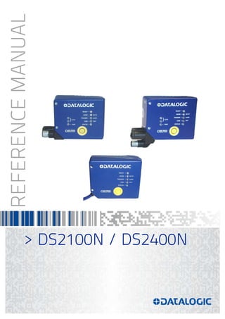
- 1. REFERENCEMANUAL > DS2100N / DS2400N
- 2. Datalogic Automation Srl Via Lavino, 265 40050 - Monte S. Pietro Bologna - Italy DS2100N / DS2400N Reference Manual Ed.: 03/2015 © 2007 – 2015 Datalogic Automation S.r.l. ALL RIGHTS RESERVED. Protected to the fullest extent under U.S. and international laws. Copying, or altering of this document is prohibited without express written consent from Datalogic Automation S.r.l. Datalogic and the Datalogic logo are registered trademarks of Datalogic S.p.A. in many countries, including the U.S.A. and the E.U. ID-NET, Genius and X-PRESS are trademarks of Datalogic Automation S.r.l. All other brand and product names mentioned herein are for identification purposes only and may be trademarks or registered trademarks of their respective owners. Datalogic shall not be liable for technical or editorial errors or omissions contained herein, nor for incidental or consequential damages resulting from the use of this material. 30/03/15
- 3. iii CONTENTS REFERENCES ............................................................................................................vi Conventions................................................................................................................. vi Reference Documentation........................................................................................... vi Support Through The Website..................................................................................... vi Patents......................................................................................................................... vi SAFETY AND COMPLIANCE NOTICES...................................................................vii Laser Safety.................................................................................................................vii Power Supply............................................................................................................... ix FCC Compliance ......................................................................................................... ix CE Compliance............................................................................................................ ix Bureau of Indian Standard (BIS).................................................................................. ix Handling........................................................................................................................ x GENERAL VIEW........................................................................................................xii 1 RAPID CONFIGURATION ...........................................................................................1 Step 1 – Connect the System.......................................................................................1 Step 3 – X-PRESS™ Configuration..............................................................................4 Step 4 – Installing Genius™ Configuration Program ....................................................7 Step 5 – Test Mode ....................................................................................................12 Advanced Scanner Configuration...............................................................................13 2 INTRODUCTION ........................................................................................................14 2.1 Product Description ....................................................................................................14 2.1.1 Indicators ....................................................................................................................15 2.2 ID-NET™ ....................................................................................................................15 2.2.1 How To Setup/Configure the Scanner Network..........................................................17 2.3 X-PRESS™ Human Machine Interface ......................................................................18 2.3.1 Diagnostic Indication...................................................................................................18 2.3.2 X-PRESS™ Functions................................................................................................19 2.4 External Memory Backup & Restore...........................................................................21 2.5 Automatic Scanner Replacement ...............................................................................24 2.6 Subzero Temperature Models ....................................................................................25 2.7 IP Address Alignment using Genius™ Discovery.......................................................26 2.8 Model Descriptions .....................................................................................................29 2.8.1 DS2100N Models........................................................................................................29 2.8.2 DS2400N Models........................................................................................................30 2.9 Accessories ................................................................................................................31 3 MECHANICAL INSTALLATION ................................................................................33 3.1 Package Contents ......................................................................................................33 3.2 Overall Dimensions.....................................................................................................34 3.2.1 Mounting the Scanner.................................................................................................38 3.3 Mounting Scanner Accessories ..................................................................................39 3.3.1 Mounting a GFC-2020 Accessory Lateral Output Deflection Mirror ...........................39 3.3.2 Mounting a GFC-2100 Accessory Lateral Output Deflection Mirror ...........................40 3.3.3 Mounting a GFC-200 Accessory Contact Reading Mirror ..........................................41 3.3.4 Mounting an OM2000N Accessory Oscillating Mirror .................................................44 3.4 Positioning ..................................................................................................................47 4 ELECTRICAL INSTALLATION..................................................................................48 4.1 Power Supply..............................................................................................................49
- 4. iv 4.2 Main Serial Interface...................................................................................................49 4.2.1 RS232 Interface..........................................................................................................50 4.2.2 RS485 Full-Duplex Interface.......................................................................................51 4.2.3 RS485 Half-Duplex Interface......................................................................................52 4.3 ID-NET™ Interface .....................................................................................................54 4.3.1 ID-NET™ Cables........................................................................................................54 4.3.2 ID-NET™ Response Time..........................................................................................55 4.3.3 ID-NET™ Network Termination..................................................................................59 4.4 Auxiliary RS232 Interface ...........................................................................................59 4.5 Inputs..........................................................................................................................60 4.5.1 Code Verifier...............................................................................................................63 4.6 Outputs .......................................................................................................................63 4.7 User Interface - Host...................................................................................................65 5 TYPICAL LAYOUTS ..................................................................................................66 5.1 Point-to-Point..............................................................................................................66 5.3 Profinet-IO Networks ..................................................................................................69 5.3.1 Single Station Layout..................................................................................................69 5.3.2 Multi Station Layout ....................................................................................................70 5.4 ID-NET™ Synchronized Networks .............................................................................71 5.5 ID-NET™ Multidata Networks.....................................................................................76 5.6 Pass-Through .............................................................................................................77 5.7 Other Layouts .............................................................................................................78 6 READING FEATURES...............................................................................................79 6.1 Advanced Code Reconstruction (ACR-Lite) ...............................................................79 6.1.1 Important ACR-Lite Reading Conditions.....................................................................80 6.1.2 Tilt Angle for Advanced Code Reconstruction ............................................................80 6.1.3 Advanced Code Reconstruction Reading Conditions.................................................82 6.2 Linear Code Reading..................................................................................................83 6.2.1 Step-Ladder Mode......................................................................................................83 6.2.2 Picket-Fence Mode.....................................................................................................84 6.3 Performance ...............................................................................................................85 6.3.1 Raster .........................................................................................................................86 6.4 Reading Diagrams......................................................................................................87 6.4.1 DS2100N ....................................................................................................................87 6.4.2 DS2400N ....................................................................................................................93 7 MAINTENANCE .........................................................................................................96 7.1 Cleaning......................................................................................................................96 8 TROUBLESHOOTING ...............................................................................................97 8.1 General Guidelines.....................................................................................................97 9 TECHNICAL FEATURES.........................................................................................100 A ALTERNATIVE CONNECTIONS FOR SERIAL MODELS......................................103 Power, COM and I/O Connector...............................................................................103 ID-NET™ Network Termination................................................................................104 Inputs........................................................................................................................104 Outputs .....................................................................................................................105 User Interface - Serial Host ......................................................................................106 B ALTERNATIVE CONNECTIONS FOR ETHERNET MODELS................................107 Power, COM and I/O Connector...............................................................................107
- 5. v On-Board Ethernet Connector..................................................................................108 ID-NET™ Network Termination................................................................................108 Inputs........................................................................................................................108 Outputs .....................................................................................................................109 C CONNECTIONS FOR PROFINET-IO MODELS ......................................................111 On-Board Profinet-IO Connectors (2).......................................................................111 Power........................................................................................................................111 GLOSSARY..............................................................................................................112 INDEX.......................................................................................................................115
- 6. vi REFERENCES CONVENTIONS This manual uses the following conventions: “User” or “Operator” refers to anyone using the scanner. “Device” refers to the scanner. “You” refers to the System Administrator or Technical Support person using this manual to install, mount, operate, maintain or troubleshoot the scanner. REFERENCE DOCUMENTATION The documentation related to the scanner management is listed below: CBX100 Installation Manual CBX100 LT Installation Manual (for Subzero models) CBX500 Installation Manual CBX Accessory Manuals OM2000N Installation Manual Genius™ Help On Line SUPPORT THROUGH THE WEBSITE Datalogic provides several services as well as technical support through its website. Log on to www.datalogic.com and click on the Industrial Automation links for further information: PRODUCTS – FIXED INDUSTRIAL BARCODE READERS Select your product from the links on the Fixed Industrial Barcode Readers page. The product page describes specific Info, Features, Applications, Models, Accessories, and Downloads including documentation, software drivers, and utility programs. SUPPORT & SERVICES – INDUSTRIAL AUTOMATION Several links from the Industrial Automation list take you to additional services such as: Service Program which contains Maintenance Agreements and Warranty Extensions; Repair Centers; On-Line RMA Return Material Authorizations; Technical Support through email or phone; Downloads for additional downloads. PATENTS See www.patents.datalogic.com for patent list. These products are covered by one or more of the following patents: Utility patents: US5992740; US6443360; US6056198; US6273336; EP0789315B1; EP1217571B1; GB2345568B
- 7. vii SAFETY AND COMPLIANCE NOTICES CAUTION: Subzero model scanners must not be opened in an uncontrolled environment. LASER SAFETY The following information is provided to comply with the rules imposed by international authorities and refers to the correct use of the scanner. Standard Regulations This scanner utilizes a low-power laser diode. Although staring directly at the laser beam momentarily causes no known biological damage, avoid staring at the beam as one would with any very strong light source, such as the sun. Avoid that the laser beam hits the eye of an observer, even through reflective surfaces such as mirrors, etc. This product conforms to the applicable requirements of IEC 60825-1 and complies with 21 CFR 1040.10 except for deviations pursuant to Laser Notice N° 50, date June 24, 2007. The scanner is classified as a Class 2 laser product according to IEC 60825-1 regulations. There is a safety device, which allows the laser to be switched on only if the motor is rotating above the threshold for its correct scanning speed. The laser beam can be switched off through a software command (see also the Genius™ Help On Line). WARNING: Use of controls or adjustments or performance of procedures other than those specified herein may result in exposure to hazardous visible laser light. The laser light is visible to the human eye and is emitted from the window on the front of the scanner (Figure A, 7). Warning labels indicating exposure to laser light and the device classification are applied onto the body of the scanner (Figure A, 1).
- 8. viii Disconnect the power supply when opening the device during maintenance or installation to avoid exposure to hazardous laser light. The laser diode used in this device is classified as a class 3B laser product according to EN 60825-1 regulations and as a Class IIIb laser product according to CDRH regulations. Any violation of the optic parts in particular can cause radiation up to the maximum level of the laser diode (35 mW at 630 to 680 nm). Warning and Device Class Labels Produit(s) conforme selon 21CFR 1040.10 sauf des dérogations relatives à la Laser Notice N° 50, date Juin 24, 2007. Dans le paquet il y a l’étiquette(s) pour les pays où le texte d'avertissement en français sont obligatoires. Le(s) mettre sur le produit à la place de la version anglaise. Exemple d'étiquettes d'avertissement laser
- 9. ix POWER SUPPLY This product is intended to be installed by Qualified Personnel only. This product is intended to be connected to a UL Listed or CSA Certified Power Unit marked LPS or “Class 2”. FCC COMPLIANCE Modifications or changes to this equipment without the expressed written approval of Datalogic could void the authority to use the equipment. This device complies with PART 15 of the FCC Rules. Operation is subject to the following two conditions: (1) This device may not cause harmful interference, and (2) this device must accept any interference received, including interference which may cause undesired operation. This equipment has been tested and found to comply with the limits for a Class A digital device, pursuant to part 15 of the FCC Rules. These limits are designed to provide reasonable protection against harmful interference when the equipment is operated in a commercial environment. This equipment generates, uses, and can radiate radio frequency energy and, if not installed and used in accordance with the instruction manual, may cause harmful interference to radio communications. Operation of this equipment in a residential area is likely to cause harmful interference in which case the user will be required to correct the interference at his own expense. CE COMPLIANCE Warning: This is a Class A product. In a domestic environment this product may cause radio interference in which case the user may be required to take adequate measures. BUREAU OF INDIAN STANDARD (BIS) Self Declaration – Conforming to IS 13252 (Part 1):2010, R-41009288.
- 10. x HANDLING The scanner is designed to be used in an industrial environment and is built to withstand vibration and shock when correctly installed, however it is also a precision product and therefore before and during installation it must be handled correctly to avoid damage. avoid that the scanners hit one another causing damage. They should be handled separately. avoid that the scanners are dropped (exceeding shock limits). do not fine tune the positioning by striking the scanner or bracket.
- 11. xi do not weld the scanner into position which can cause electrostatic, heat or output window damage. do not spray paint near the scanner which can cause output window damage.
- 12. xii GENERAL VIEW DS2100N / DS2400N Serial and Subzero Models Figure A 8 9 5 6 7 11 12 3 1 10 4 13 2 1 Warning and Device Class Labels 2 3 4 5 6 Power - Serial Interfaces - I/O Cable Power On LED Mounting Holes (4) Ready LED Good LED 8 Laser Beam Output Window 9 10 11 12 Com LED Status LED X-PRESS™ Push Button Accessory Mounting Holes 13 Subzero Model Logo 7 Trigger LED
- 13. xiii DS2100N / DS2400N Built-In Ethernet Models Figure B 10 11 7 8 9 13 14 2 1 12 4 3 5 6 1 Warning and Device Class Labels 2 3 4 5 6 Ethernet Connector Power - Serial Interfaces - I/O Connector Mounting Holes (4) Power On LED Ethernet Connection LED 8 Good LED 9 10 11 12 Trigger LED Laser Beam Output Window Com LED Status LED 13 X-PRESS™ Push Button 7 Ready LED 14 Accessory Mounting Holes
- 14. xiv DS2100N / DS2400N Profinet-IO Models Figure C 12 13 9 10 11 15 16 2 1 14 5 4 8 3 6 7 1 Warning and Device Class Labels 2 3 4 5 6 Profinet-IO Connector 1 Power Connector Profinet-IO Connector 2 Mounting Holes (4) Power On LED 9 Ready LED 10 11 12 13 Good LED Trigger LED Laser Beam Output Window Com LED 14 Status LED 7 Profinet-IO Connection 1 LED 15 X-PRESS™ Push Button 8 Profinet-IO Connection 2 LED 16 Accessory Mounting Holes
- 15. RAPID CONFIGURATION 1 1 1 RAPID CONFIGURATION NOTE: This chapter illustrates a Stand Alone application. For other types of installations, such as ID-NET™, Fieldbus, Pass-Through, Layout, etc., refer to chapters 4, and 5. For complete scanner configuration using the Genius™ configuration program, refer to the Context-Sensitive Help On-Line. STEP 1 – CONNECT THE SYSTEM To connect the system in a Stand Alone configuration, you need the hardware indicated in Figure 1. In this layout the data is transmitted to the Host on the main serial interface. In Local Echo communication mode, data is transmitted on the RS232 auxiliary interface independently from the main interface selection. When On-Line Operating mode is used, the scanner is activated by an External Trigger (photoelectric sensor) when the object enters its reading zone. Figure 1 – Scanner in Stand Alone Layout READY GOOD TRIGGER COM STATUS SETUP LEARN TEST ETH PWR DS2400N Host PG 6000 P.S.* * Presence Sensor (for On-Line mode) MAIN I/O, AUX CBX100/500
- 16. DS2100N/DS2400N REFERENCE MANUAL 2 1 CBX100/500 Pinout The table below gives the pinout of the CBX100/500 terminal block connectors. Use this pinout when the scanner reader is connected by means of the CBX100/500: CBX100/500 Terminal Block Connectors Input Power Outputs Vdc Power Supply Input Voltage + +V Power Source - Outputs GND Power Supply Input Voltage - -V Power Reference - Outputs Earth Protection Earth Ground O1+ Output 1 + O1- Output 1 - Inputs O2+ Output 2 + +V Power Source – External Trigger O2- Output 2 - I1A External Trigger A (polarity insensitive) Auxiliary Interface I1B External Trigger B (polarity insensitive) TX Auxiliary Interface TX -V Power Reference – External Trigger RX Auxiliary Interface RX +V Power Source – Inputs SGND Auxiliary Interface Reference I2A Input 2 A (polarity insensitive) ID-NET™ I2B Input 2 B (polarity insensitive) REF Network Reference -V Power Reference – Inputs ID+ ID-NET™ network + Shield ID- ID-NET™ network - Shield Network Cable Shield Main Interface RS232 RS485 Full-Duplex RS485 Half-Duplex TX TX+ RTX+ RTS TX- RTX- RX *RX+ CTS *RX- SGND SGND SGND * Do not leave floating, see par. 4.2.2 for connection details. CAUTION: Do not connect GND, SGND and REF to different (external) ground references. GND, SGND and REF are internally connected through filtering circuitry which can be permanently damaged if subjected to voltage drops over 0.8 Vdc.
- 17. RAPID CONFIGURATION 3 1 Step 2 – Mounting and Positioning the System 1. To mount the scanner, use the mounting bracket to obtain the most suitable position for the reader as shown in the figures below. Figure 2 - Positioning with Mounting Bracket 2. When mounting the scanner take into consideration these three ideal label position angles: Skew 10° to 30°, Tilt 0° and Pitch 0°. Assure at least 10° Minimize Figure 3 –Skew and Tilt Angles Minimize Figure 4 – Pitch Angle 3. Refer to the Reading Diagrams in par. 6.4 to decide the distance your scanner should be positioned at. Skew Tilt Skew Pitch S T P
- 18. DS2100N/DS2400N REFERENCE MANUAL 4 1 STEP 3 – X-PRESS™ CONFIGURATION X-PRESS™ is the intuitive Human Machine Interface designed to improve ease of installation and maintenance. Status and diagnostic information are clearly presented by means of the five colored LEDs, whereas the single push button gives immediate access to the following relevant functions: AutoSetup to self-optimize and auto-configure reading performance in demanding applications AutoLearn to self-detect and auto-configure for reading unknown barcodes (by type and length) Test Mode with bar-graph visualization to check static reading performance NOTE: If using the OM2000N accessory, when entering the X-PRESS™ interface, the Oscillating Mirror remains in the default fixed position (-15°) in order to make barcode reading easier while performing the X-PRESS™ functions. The colors and meaning of the five LEDs are illustrated in the following table: READY (green) This LED indicates the device is ready to operate. For Subzero models this LED blinks during the warm-up phase. GOOD (green) This LED confirms successful reading. TRIGGER (yellow) This LED indicates the status of the reading phase. * COM (yellow) This LED indicates active communication on main serial port. ** STATUS (red) This LED indicates a NO READ result. * In On-Line mode the TRIGGER LED corresponds to the active reading phase signaled by the Presence Sensor. In Automatic and Continuous modes the TRIGGER LED is always on indicating that the reader is ready to read a code. ** When connected to a Fieldbus network through the CBX500, the COM LED is always active, even in the absence of data transmission, because of polling activity on the Fieldbus network. During the reader startup (reset or restart phase), all the LEDs blink for one second. PWR (blue) This LED indicates that the reader is connected to the power supply. (This LED is located next to the cable on Serial models). ETH (yellow) This LED indicates connection to the on-board Ethernet or Profinet-IO network. READY GOOD TRIGGER COM STATUS SETUP LEARN TEST ETH PWR
- 19. RAPID CONFIGURATION 5 1 Auto Learn If you are configuring your scanner using X-PRESS™, you must start with the Auto Learn procedure. 1. Enter the Auto Learn function by holding the X-PRESS™ push button pressed until the LEARN LED is on. 2. Release the button to enter the Auto Learn function. Once entered, the reader starts a procedure to automatically detect and recognize barcodes (by type and length), which are presented to it (*). The laser turns on and the LEARN LED blinks to indicate the ongoing process. SETUP LEARN TEST green green yellow yellow red READY GOOD TRIGGER COM STATUS Figure 5 – X-PRESS™ Interface: Auto Learn Function The procedure is as follows: A) place the desired barcode on the scanline. B) wait until the LEARN LED stays steady on (indicating the reader has detected the barcode). C) repeat, if needed, the above two steps to program up to 10 different barcodes (the LEARN LED returns to the blinking state for the next code). If more than one barcode is detected in the scan line, the Multi Label mode is enabled (refer to the “2K/4K Family Software Configuration Parameter Guide” Help file). 3. Exit the process by pressing the X-PRESS™ push button once. The scanner will restart at the end of the process, and then the detected barcodes are automatically configured in scanner memory. NOTE: If the barcode cannot be read because of low contrast or excessive ambient light, you can perform the AutoSetup function to optimize the optical parameters. Then you can perform AutoLearn to recognize the barcode symbology. NOTE: On exit from Autolearn, the following parameters are forced: Code Combination = Single Label, Reading Mode = Linear. If necessary, these parameters can be changed through Genius™. * In case of Programming Barcodes, refer to the “Setup Procedure Using Programming Barcodes” document in the product CD.
- 20. DS2100N/DS2400N REFERENCE MANUAL 6 1 Auto Setup (Optional) At the end of the Auto Learn procedure, you have the possibility to follow the Auto Setup procedure to set up the reading parameters. 1. Enter the Auto Setup function by holding the X-PRESS™ push button pressed until the SETUP LED is on. 2. Release the button to enter the Auto Setup function. 3. Once entered, if a barcode label is positioned in front of the scanline, the scanner automatically performs the optimal setup of the reading parameters for that specific barcode. SETUP LEARN TEST green green yellow yellow red READY GOOD TRIGGER COM STATUS Figure 6 – X-PRESS™ Interface: Auto Setup Function The procedure is as follows: A) place the desired barcode on the scanline. B) enter the AutoSetup function (the laser turns on and the SETUP LED blinks to indicate the ongoing process) C) wait until the SETUP LED stays steady on (indicating the reader has detected the barcode) This procedure ends either when the barcode is successfully decoded or after a timeout of about 7 (seven) seconds. The scanner will restart at the end of the process, and then the optimized reading parameters for that barcode are automatically configured in scanner memory. NOTE: If your application has been configured using X-PRESS™, go to STEP 5. Reset Scanner to Factory Default (Optional) If it ever becomes necessary to reset the scanner to the factory default values, you can perform this by holding the X-PRESS™ push-button pressed while powering up the scanner and waiting for all LEDs to blink simultaneously three times before releasing the push button. This procedure takes ≈ 5-6 seconds for Serial Models, ≈ 10 seconds for Ethernet Models, ≈ 20 seconds for Profinet-IO models. At the end of the procedure the Configuration and Environmental parameters are reset. If connected through a CBX500 with display module, the message "Default Set" is shown on the display.
- 21. RAPID CONFIGURATION 7 1 STEP 4 – INSTALLING GENIUS™ CONFIGURATION PROGRAM Genius™ is a Datalogic scanner configuration tool providing several important advantages: Wizard approach for new users; Multi-language version; Defined configuration directly stored in the reader; Communication protocol independent from the physical interface allowing to consider the reader as a remote object to be configured and monitored. To install Genius™, turn on the PC that will be used for the configuration, running Windows 98, 2000/NT, XP, Vista or 7, then insert the Genius™ CD-ROM, wait for the CD to autorun and follow the installation procedure. This configuration procedure assumes scanner connection to a CBX100/500. Genius™, running on a laptop computer, is connected to the scanner auxiliary port through the CBX100/500 9-pin connector. To communicate with the scanner, Genius™ performs an auto baudrate detection starting from its default parameters which are 115200, 8, N, 1. These parameters can also be set in the Genius™ Tools>Options>Communications window. Wizard for Quick Reader Setup After installing the Genius™ software program the following window appears asking the user to choose the desired configuration level. Figure 7 - Genius™ Wizard Opening Window The Wizard option is advised for rapid configuration or new users, since it shows a step-by- step scanner configuration.
- 22. DS2100N/DS2400N REFERENCE MANUAL 8 1 1. Select the Create a new configuration button. You will be guided through the configuration being asked to define the following parameters: a. Barcode selection and definition
- 23. RAPID CONFIGURATION 9 1 b. Operating mode selection and definition c. Digital Outputs configuration
- 24. DS2100N/DS2400N REFERENCE MANUAL 10 1 d. Hardware interface selection e. Output data format configuration The On Line operating Mode requires the reader to be connected to an External Trigger/Presence Sensor using I1A and I1B inputs. The Automatic operating mode does not require connection to an external Presence Sensor. When working in this mode the reader is continuously scanning, while the reading phase is activated each time a barcode enters the reader reading zone. The reader stops reading after an N number of scans without a code. Barcode characters are transmitted on the serial interface. In case of a failed reading phase no message is sent to the host computer.
- 25. RAPID CONFIGURATION 11 1 2. After defining the parameter values the following window appears allowing to complete the reader configuration as follows: Saving the configuration to disk; Switching to Advanced mode; Sending the configuration to the scanner. 3. After sending the configuration to the scanner you have completed the configuration process. 4. By clicking Finish, the System Information window will be displayed with specific information concerning the scanner.
- 26. DS2100N/DS2400N REFERENCE MANUAL 12 1 STEP 5 – TEST MODE Use a code suitable to your application to test the system. Alternatively, you can use the Datalogic Test Chart (Code 39, Code Interleaved 2/5). 1. Enter the Test mode function by holding the X-PRESS™ push button pressed until the TEST LED is on. 2. Release the button to enter the Test mode function. Once entered, the Bar-Graph on the five LEDs is activated and if the scanner starts reading barcodes the Bar-Graph shows the Good Read Rate. In case of no read condition, only the STATUS LED is on and blinks. SETUP LEARN TEST green green yellow yellow red READY GOOD TRIGGER COM STATUS Figure 8 – X-PRESS™ Interface: Test Mode Function 3. To exit the Test Mode, press the X-PRESS™ push button once. NOTE: By default, the Test Mode exits automatically after two minutes.
- 27. RAPID CONFIGURATION 13 1 ADVANCED SCANNER CONFIGURATION The ADVANCED selection available when starting the Genius™ program is addressed to expert users being able to complete a detailed scanner configuration. By choosing this option it is possible either to start a new scanner configuration or to open and modify an old one. The desired parameters can be defined in the following window, similar to the MS Explorer: Figure 9 - Genius™ Parameter Explorer Window Host Mode Programming The scanner can also be configured from a host computer using the Host Mode programming procedure, by commands via the serial interface. See the Host Mode Programming file on the CD-ROM. Alternative Layouts The ID-NET™ is a built-in high-speed interface dedicated for high-speed scanner interconnection. ID-NET™ is in addition to the Main and Auxiliary serial interfaces. If you need to install an ID-NET™ network refer to chapters 4, and 5 of this Reference Manual. The scanner can also be configured for alternative layouts by reading programming barcodes. See the "Setup Procedure Using Programming Barcodes" printable from the CD-ROM. If you need to install an Ethernet network, Fieldbus network or Pass-Through network, refer to chapters 4, and 5 of this Reference Manual.
- 28. DS2100N/DS2400N REFERENCE MANUAL 14 2 2 INTRODUCTION 2.1 PRODUCT DESCRIPTION The DS2100N/DS2400N laser scanner satisfies the most advanced needs of a wide range of users. It has been developed focusing on the realistic requirements of its target market. The outstanding result is an extremely compact, cost-effective and easy to use industrial scanner. Standard Application Program A standard application program is factory-loaded onto the scanner. This program controls barcode reading, serial port interfacing, data formatting and many other operating and control parameters. It is completely configurable from a host computer through the Genius™ utility program provided on CD with the scanner, or via the serial interface (Genius™ based Host Mode Programming). Custom Application Programs If the Standard Application Program does not meet your requirements, please contact your local Datalogic distributor. Some of the main features are listed below: ACR-Lite (Advanced Code Reconstruction) small dimensions and light weight software programmable scanning speed on all models linear and raster version completely configurable via serial interface (Genius™) 3 serial communication interfaces (Main, Auxiliary, ID-NET™) supply voltage from 10 to 30 Vdc (24 Vdc 10% for Subzero models) reads all popular codes test mode to verify the reading features and exact positioning of the scanner without the need for external tools programmable in 4 different operating modes to suit the most various barcode reading system requirements code verifier low power consumption The scanner uses a solid-state laser diode as a light source; the light emitted has a wavelength between 630 and 680 nm. Refer to the section “Safety Precautions” at the beginning of this manual for information on laser safety. The protection class of the enclosure is IP65, the reader is therefore suitable for industrial environments where high protection against harsh external conditions is required.
- 29. INTRODUCTION 15 2 2.1.1 Indicators The five LEDs on the side of the scanner (Figure A) indicate the following: READY (green) This LED indicates the device is ready to operate. For Subzero models this LED blinks during the warm-up phase. GOOD (green) This LED confirms successful reading. TRIGGER (yellow) This LED indicates the status of the reading phase. * COM (yellow) This LED indicates active communication on main serial port. ** STATUS (red) This LED indicates a NO READ result. * In On-Line mode the TRIGGER LED corresponds to the active reading phase signaled by the Presence Sensor. In Automatic and Continuous modes the TRIGGER LED is always on indicating that the reader is ready to read a code. ** When connected to a Fieldbus network through the CBX500, the COM LED is always active, even in the absence of data transmission, because of polling activity on the Fieldbus network. During the reader startup (reset or restart phase), all the LEDs blink for one second. PWR (blue) This LED indicates that the reader is connected to the power supply. (This LED is located next to the cable on Serial models). ETH (yellow) This LED indicates connection to the on-board Ethernet or Profinet-IO network. 2.2 ID-NET™ The ID-NET™ is a built-in high-speed interface dedicated for high- speed scanner interconnection. The ID-NET™ is in addition to the Main and Auxiliary serial interfaces. The following network configurations are available: ID-NET™ M/S Synchronized: Single station – multiple scanners ID-NET™ interface allows local connection of multiple scanners reading different sides of the same target. All scanners share a single presence sensor and activate/deactivate simultaneously. At the end of each reading phase a single data message is transmitted to the host. Thanks to ID-NET™, data communication among scanners is highly efficient so that an immediate result will be available.
- 30. DS2100N/DS2400N REFERENCE MANUAL 16 2 ID-NET™ M/S Multidata: Multiple stations – single scanner ID-NET™ interface allows connection of scanners reading objects placed on independent conveyors. All scanners are typically located far away from each other and they use a dedicated presence sensor. At the end of each reading phase, each scanner transmits its own data message to the host. Thanks to ID-NET™, data collection among readers is accomplished at a high speed without the need of external multiplexing device. This leads to an overall cost reduction and to a simple system wiring.
- 31. INTRODUCTION 17 2 2.2.1 How To Setup/Configure the Scanner Network A complete ID-NET™ scanner network can be rapidly setup, as follows: Mounting & Connection 1. Mechanically mount/install all the readers (refer to par. 3.2 and 3.4). 2. Wire ID-NET™ (refer to par. 4.3). 3. Connect the planned Master scanner to a PC by means of the Genius™ configuration software. 4. Power up the entire system. Configuration 1. Launch Genius™. 2. From the Genius™ Device Menu select “Local Device Network Settings” and program the Role of the Master scanner (Synchronized or Multidata). This procedure requires the Network Baud Rate be the same for all Slaves and Master, (500 kbs is the default value). It can be changed after network setup using Genius™ through the Master scanner. See also the alternative procedure in the note below. 3. At the prompt to "Send updated Network configuration to the Local Device" (Master) choose "Yes". 4. Then run the NET-AUTOSET procedure from the Icon in the Devices Area. Genius™ sets all slave scanners according to the Master Role (Synchronized or Multidata), and assigns each a random address. If necessary, this address can be changed through the Network Wizard. 5. Configure the System parameters via Genius™. 6. If using the CBX connection box equipped with a BM100 Backup module, perform System Backup at the Master. See par. 2.4 of this manual or the BM100 or BM150 manuals for details. The scanner network is ready. NOTE: If necessary, the ID-NET™ baudrate can be set individually on each Slave scanner to match the Master. Connect each Slave to Genius™ and set the Reading System Layout > Network Baudrate parameter. Then follow the procedure above. NOTE: An alternative method of programming scanner address and role assignment can be accomplished by using the "Connectivity Programming Barcodes" (refer to the "Setup Procedure Using Programming Barcodes" document on the product CD).
- 32. DS2100N/DS2400N REFERENCE MANUAL 18 2 2.3 X-PRESS™ HUMAN MACHINE INTERFACE X-PRESS™ is the intuitive Human Machine Interface designed with the precise goal of improving ease of installation and maintenance. Status and diagnostic information are clearly presented by means of five-colored LEDs, whereas the single multi-function key gives immediate access to relevant functions: Autosetup to self-optimize reading performance in demanding applications Autolearn to self-detect unknown barcodes Test Mode with bar-graph visualization to check static reading performance X-PRESS™ is the common interface adopted in all new products: “You learn one, you can use them all”. The colors and meaning of the five LEDs when in the one of the operating modes (On-Line, Automatic or Continuous) are illustrated in par 2.1.1. NOTE: The X-PRESS™ functions do not work if the motor or laser are turned off, see chp. 8 for details. 2.3.1 Diagnostic Indication The “STATUS” and “READY” LEDs blink simultaneously to signal the presence of a failure. Diagnostic message transmission on interfaces can be enabled to provide details about specific failure conditions. At the same time one or more LEDs light up according to the following scheme: SETUP LEARN TEST green green yellow yellow red READY GOOD TRIGGER COM STATUS LED STATUS READY BLINK GOOD ON to indicate any Failure different than Motor or Laser failures. TRIGGER ON to indicate a Motor Failure. COM ON to indicate a Laser Failure. STATUS BLINK READY GOOD TRIGGER COM STATUS SETUP LEARN TEST
- 33. INTRODUCTION 19 2 2.3.2 X-PRESS™ Functions Quick access to the following functions is provided by an easy procedure using the push button: 1 – Press the button (the STATUS LED will give a visual feedback). 2 – Hold the button until the specific function LED is on (TEST, LEARN or SETUP). 3 – Release the button to enter the specific function. SETUP LEARN TEST green green yellow yellow red READY GOOD TRIGGER COM STATUS Once button is pressed, the cycle of LEDs activation is as follows: SETUP LEARN TEST green green yellow yellow red READY GOOD TRIGGER COM STATUS SETUP LEARN TEST green green yellow yellow red READY GOOD TRIGGER COM STATUS SETUP LEARN TEST green green yellow yellow red READY GOOD TRIGGER COM STATUS Release button to Exit Release button to enter Test Mode Release button to enter AutoLearn SETUP LEARN TEST green green yellow yellow red READY GOOD TRIGGER COM STATUS SETUP LEARN TEST green green yellow yellow red READY GOOD TRIGGER COM STATUS Release button to enter AutoSetup (cycle) Release button to Exit Test Mode Function Once entered, the Bar-Graph on the five LEDs is activated and if the scanner starts reading barcodes the Bar-Graph shows the Good Read Rate. In case of no read condition, only the STATUS LED is on and blinks. To exit the Test Mode, press the X-PRESS™ push button once.
- 34. DS2100N/DS2400N REFERENCE MANUAL 20 2 AutoLearn Function Once entered, the reader starts a procedure to automatically detect and recognize barcodes (by type and length), which are presented to it1 . The laser turns on and the LEARN LED blinks to indicate the ongoing process. The procedure is as follows: - place the desired barcode on the scanline. - wait until the LEARN LED stays steady on (indicating the reader has detected the barcode). - repeat, if needed, the above two steps to program up to 10 different barcodes (the LEARN LED returns to the blinking state for the next code). If more than one barcode is detected in the scan line, the Multi Label mode is enabled (refer to the “2K/4K Family Software Configuration Parameter Guide” Help file). - exit the process by pressing the X-PRESS™ push button once. The scanner will restart at the end of the process, and then the detected barcodes are automatically configured in scanner memory. AutoSetup Function Once entered, if a barcode label is positioned in front of the scanline, the scanner automatically performs the optimal setup of the reading parameters for that specific barcode. The procedure is as follows: - place the desired barcode on the scanline. - enter the AutoSetup function (the laser turns on and the SETUP LED blinks to indicate the ongoing process). - wait until the SETUP LED stays steady on (indicating the reader has detected the barcode). This procedure ends either when the barcode is successfully decoded or after a timeout of about 7 (seven) seconds. The scanner will restart at the end of the process, and then the optimized reading parameters for that barcode are automatically configured in scanner memory. NOTE: The AutoSetup function does not modify the programmed barcode symbologies. If needed, the AutoLearn function can be performed after Autosetup. 1 In case of Programming Barcodes, refer to the “Setup Procedure Using Programming Barcodes” document in the product CD.
- 35. INTRODUCTION 21 2 Reset Scanner to Factory Default If it ever becomes necessary to reset the scanner to the factory default values, you can perform this procedure by holding the X-PRESS™ push button pressed while powering up the scanner. At the end of the procedure (about 5-6 seconds), the Configuration and Environmental parameters are reset, all LEDs blink simultaneously 3 times and the message "Default Set" is shown on the display. 2.4 EXTERNAL MEMORY BACKUP & RESTORE By selecting "External Memory Backup & Restore" from the Device menu, the following dialog box appears allowing Complete Configuration and Environmental parameter storage for network and reading devices. Backup & Restore can be applied to any connected device through which backup memory is available, regardless of the devices' network configuration. Backup & Restore automatically checks whether a previous backup or configuration is already stored in backup memory for each device, speeding up the procedure and making it more secure. The Backup & Restore function is supported by DS2100N, DS2400N, DS4800 when connected to or through: CBX + BM100 and/or BM2x0 QL500 (Ethernet TCP/IP) SC4000 ID-NET Controller QLM-Series Gateways
- 36. DS2100N/DS2400N REFERENCE MANUAL 22 2 NOTE: Before executing a Backup on a BM100 backup module make sure the Write Protection switch is set to Unlocked. If BM100 and BM2x0 are both installed B&R is automatically performed only on the BM100 module. BM2x0 can execute B&R only with Network up and running (network cable connected). QL500 can backup up to 10 nodes (Master + 9 slaves). In the pictures above the Backup/Restore Dialog is shown: the Devices window lists all of the available devices in the current configuration, the Backup Contents window lists any previous device backups. To perform a Backup: 1. Press the Backup button (you will be warned that all previous backups will be overwritten) 2. The Status window shows information as the backup procedure is being executed To perform a Restore: 1. Press the Restore button (you will be warned that all scanner configurations will be overwritten) 2. The Status window shows information as the restore procedure is being executed The Restore function also provides easy and secure Single Device Replacement: 1. Remove the scanner to be replaced
- 37. INTRODUCTION 23 2 2. Connect the new scanner (make sure the new scanner has been previously set to default) 3. Run the Restore procedure by pressing the Restore Button (see: Restore procedure) NOTE: If the Automatic Scanner Replacement parameter is enabled the Restore procedure starts automatically when the new scanner is recognized. To Erase any previous Backup: 1. Press the Erase button 2. All backups are deleted The Status window shows the status of the backup procedure as it is being executed. The following is a list of possible error messages: Module not present: backup module not mounted (BM100) or not ready (QL500 , BM2x0, SC4000, QLMxxx), or Search for Backup Memory at Device Startup parameter disabled Unable to Read Backup State: Genius is unable to get connected to the device Backup function not allowed: when device is in X-PRESS™ Menu mode (BM100) or is out of memory (QL500) Failed! (Device not found): Master is unable to reach the addressed device Failed! (Module is write protected): BM100 Write Protection switch is set to Locked
- 38. DS2100N/DS2400N REFERENCE MANUAL 24 2 2.5 AUTOMATIC SCANNER REPLACEMENT This parameter allows single scanner replacement to take place automatically (at power on time only) whenever a scanner substitution is made. Data for the Automatic Scanner Replacement are stored in the backup memory [BM100 Backup Module or QLMxxx Gateway]. To correctly activate the Automatic Scanner Replacement feature follow these steps: Master/Slave Configuration: 1. Connect to the Master and properly configure all of the scanners in your system according to your application needs. 2. Enable the Automatic Scanner Replacement parameter on the Master, then Send the configuration to the Master. 3. Backup the complete network configuration by selecting Backup & Restore in the Device drop-down list from the Genius™ menu. 4. Get the Masters' configuration and verify that the Automatic Scanner Replacement parameter is enabled. The Automatic Scanner Replacement is now enabled. If any network scanner (Master or Slave) is ever replaced by a new one (which must be set to the Default Configuration or have the proper node address) the Automatic Scanner Replacement feature will be performed. Other Configuration: 1. Connect to the scanner and properly configure it according to your application needs. 2. Enable the Automatic Scanner Replacement parameter, then Send the configuration to the scanner. 3. Backup the configuration by selecting Backup & Restore in the Device drop-down list from the Genius™ menu. 4. Get the configuration and verify that the Automatic Scanner Replacement parameter is enabled. The Automatic Scanner Replacement is now enabled. If the scanner is ever replaced by a new one (which must be set to the Default Configuration), the Automatic Scanner Replacement feature will be performed. NOTE 1: The Automatic Scanner Replacement feature can only be performed at power up (either Master or Other: Stand Alone) and only one scanner at a time can be replaced. NOTE 2: Once the Automatic Scanner Replacement has been activated, the Restore feature is also available. NOTE 3: Once the Automatic Scanner Replacement has been activated, it will be forced if a "Reset Scanner to Factory Default" procedure is performed (by pressing and holding the X- PRESS™ button at power-up). NOTE 4: Once the Automatic Scanner Replacement has been activated, it can be disabled only by Erasing the Backup content from the backup memory or by backing up a configuration once the Automatic Scanner Replacement parameter has been disabled.
- 39. INTRODUCTION 25 2 2.6 SUBZERO TEMPERATURE MODELS The DS2400N Subzero scanner is an industrial scanner designed to operate in industrial refrigerator/freezer cells or other stable subzero degree environments, which are below the operating range of standard industrial scanners. It is not designed to move between subzero and normal environments (rapid temperature changes). The DS2400N Subzero has an intelligent microprocessor-driven and efficient internal heating system which constantly monitors and automatically controls internal temperature. Only the necessary temperature-sensitive components are heated, resulting in an efficient heating system which has very low power consumption. Upon power-up in a subzero environment, the scanner waits until these internal components are heated to within their operating temperature range. Power-up at -35 °C can take about 20 minutes before the scanner is ready to read barcodes. During this time the laser and motor remain off and the Ready LED blinks, indicating the warm-up phase. While in the warm-up phase, scanner communication is operative and the device can be configured through Genius™ or through Host Mode Programming. InternalTemperature(°C) 20 Scanner Normal Operation Starting Point Stabilized Temperature Phase Warm-Up Phase Cold Start 0 Time (min) -35 0 The DS2400N Subzero can be connected to the CBX100 LT Subzero connection box which can withstand the same low temperature environment as the scanner. A CBX100 LT all-in- one model includes a BM100 backup and restore module having an extended temperature range also for use in subzero environments.
- 40. DS2100N/DS2400N REFERENCE MANUAL 26 2 2.7 IP ADDRESS ALIGNMENT USING GENIUS™ DISCOVERY For Bulit-in Ethernet and Profinet-IO models, the scanner IP address can automatically be found on the Ethernet network by using the Genius™ Discovery utility available in the Options>Communications tab. NOTE: This feature only works for the built-in interfaces: Ethernet or Profinet-IO. Discovery Procedure: 1. Select the desired device by comparing the MAC address field with the label on the device. 2. Click the Change button to assign the desired IP address. NOTE: It is advised to use an assigned static IP address instead of DHCP.
- 41. INTRODUCTION 27 2 3. Click the Apply button. The following message is displayed because Genius can no longer communicate with the new address. Click OK. 4. Click the Refresh button. You should now see the device displayed with the newly assigned IP address. Click OK to return to the Communications folder.
- 42. DS2100N/DS2400N REFERENCE MANUAL 28 2 5. Click OK to return to Genius™ and perform a Device>Get to connect to the device.
- 43. INTRODUCTION 29 2 2.8 MODEL DESCRIPTIONS 2.8.1 DS2100N Models DS2100N scanners are described by their model number which indicates the characteristics listed in the diagram below. Not all combinations are available. For a complete list of combinations see the Models tab on the Product page of the website. Resolution Performance Linear or raster reading DS2100N - X X X X Optical Resolution 1 = Standard 2 = High Communication Interface 2 = RS232/RS485main + RS232 aux 3 = Built-in Ethernet 4 = Profinet IO Optic Version 0 = Linear 1 = Raster Performance 0 = Standard 4 = High The following tables display each version’s reading performance. Version Max Code Resolution Speed mm (mils) scans/s 1xx0 0.20 (8) 500 to 800 1xx4 0.15 (6) 800 to 1000 2xx0 0.15 (6) 500 to 800 2xx4 0.12 (5) 800 to 1000 Version Reading Distance 1xx0 40 mm (1.6 in) - 300 mm (11.8 in) on 0.50mm (20 mils) codes 1XX4 50 mm (1.8 in) - 310 mm (11.8 in) on 0.50 mm (20 mils) codes 2xx0 30 mm (1.2 in) - 90 mm (3.5 in) on 0.30 mm (12 mils) codes 2xx4 45 mm (1.8) – 100 mm (3.9 in) on 0.20 mm (8 mils) codes See reading diagrams in par. 6.4 for further details.
- 44. DS2100N/DS2400N REFERENCE MANUAL 30 2 2.8.2 DS2400N Models DS2400N scanners are described by their model number which indicates the characteristics listed in the diagram below. Not all combinations are available. For a complete list of combinations see the Models tab on the Product page of the website. Resolution Performance Linear or raster reading Special Features DS2400N - X X X X Reading Range 0 = Short 1 = Medium 2 = Long Communication Interface 2 = RS232/RS485main + RS232 aux 3 = Built – in Ethernet 4 = Profinet IO Optic Version 0 = Linear 1 = Raster Special Features 0 = Standard 5 = Heater (Subzero Temp) The following tables display each version’s reading performance. Version Max Code Resolution Speed mm (mils) scans/s 0XXX 0.20 (8) 600 to 1000 1XXX 0.25 (10) 600 to 1000 2XXX 0.35 (14) 600 to 1000 Version Reading Distance 0XXX 75 mm (3 in) - 340 mm (13.4 in) on 0.35 mm (14 mils) codes 1XXX 100 mm (3.9 in) - 440 mm (17.3 in) on 0.50 mm (20 mils) codes 2XXX 190 mm (7.5 in) - 600 mm (23.6 in) on 0.50 mm (20 mils) codes See reading diagrams in par. 6.4 for further details.
- 45. INTRODUCTION 31 2 2.9 ACCESSORIES The following accessories are available on request for the DS2100N/DS2400N scanner: Name Description Part Number Mirrors GFC-200 85° Contact Reading Mirror 93A201108 GFC-2100 2KN 90° Lateral Output Window 93A201000 GFC-2020 2KN 102° Lateral Output Mirror 93ACC1871 OM2000N Oscillating Mirror 93ACC1783 Connection Boxes CBX100 Compact Connection Box 93A301067 CBX100 All-In-One Compact Connection Box + BM100 93A301076 CBX100 LT Compact Connection Box Subzero 93A301069 CBX100 LT All-In-One Compact Connection Box Subzero + BM100 93A301085 CBX500 Modular Connection Box 93A301068 BM100 Backup Module 93ACC1808 BM150 Display Module 93ACC1809 BM200/210 Ethernet TCP/IP Module STD/IP65 93ACC1851, 93ACC1852 BM300/310 Profibus Module STD/IP65 93ACC1810, 93ACC1811 BM400 DeviceNet Module IP65 93ACC1814 BM500/510/520 Ethernet/IP Module STD/IP65/IP54 93ACC1812, 93ACC1813, 93ACC1840 BM600 CANopen Module STD 93ACC1815 BM700/710 Profinet Module STD/IP65 93ACC1816, 93ACC1886 BM1100 CC-Link Module STD 93ACC1845 BM1200/1210 Modbus TCP 93ACC1848, 93ACC1849 BA100 DIN Rail Adapters 93ACC1821 BA200 Bosch Adapters 93ACC1822 BA900 Two Cable Glands Panel 93ACC1847 QL100 Quick Link Slave ID-NET T-Connector 93ACC1860 QL150 Quick Link Slave ID-NET + Service T-Connector 93ACC1868 QL200 Quick Link Slave ID-NET + Power T-Connector 93ACC1861 QL300 Quick Link Master ID-NET Serial Host Connector 93ACC1862 QL500 Quick Link Master ID-NET Ethernet Host Connector (includes Ethernet/IP explicit messaging) 93ACC1864 QLM500 Quick Link Metal Master ID-NET - EthernNet/IP Gateway 93ACC0037 QLM600 Quick Link Metal Master ID-NET - Profibus Gateway 93ACC0033 QLM700 Quick Link Metal Master ID-NET - Profinet I/O Gateway 93ACC0038 Cables CAB-DS01-S M12-IP67 Cable To CBX or QL (1M) 93A050058 CAB-DS03-S M12-IP67 Cable To CBX or QL (3M) 93A050059 CAB-DS05-S M12-IP67 Cable To CBX or QL (5M) 93A050060 CAB-ETH-M01 M12-RJ45 IP67 Ethernet Cable (1M) 93A051346 CAB-ETH-M03 M12-RJ45 IP67 Ethernet Cable (3M) 93A051347 CAB-ETH-M05 M12-RJ45 IP67 Ethernet Cable (5M) 93A051348 CBL-1534.02 Adapter Cable Ethernet M12 to RJ45 93A050057 ETH CABLE M12-M12 1M M12-M12 Ethernet Cable (1M) for Profinet models 93A050065 ETH CABLE M12-M12 3M M12-M12 Ethernet Cable (3M) for Profinet models 93A050066 ETH CABLE M12-M12 5M M12-M12 Ethernet Cable (5M) for Profinet models 93A050067 CS-A1-02-G-03 M12 4PF-Wires Power Cable (3M) for Profinet models 95A251380 CS-A1-02-O-10 M12 4PF-Wires Power Cable (10M) for Profinet models 95A251090 AS-I Power Backbone PWR Cable, AS-I, 2 Wires, 10M 93ACC0081 AS-I Power Backbone PWR Cable, AS-I, 2 Wires, 25M 93ACC0082 AS-I Power Branch PWR Cable M12- ASI standard-1M 93ACC0067 AS-I Power Branch PWR Cable M12- ASI standard-2M 93ACC0068
- 46. DS2100N/DS2400N REFERENCE MANUAL 32 2 Name Description Part Number Sensors MEP-593 Photocell Kit - PNP (PH-1) 93ACC1791 MEP-543 Photocell Kit - NPN 93ACC1728 Power Supplies PG-6000 24 V Power Supply Unit EU (for Serial and Ethernet models – connects to CBX) 93ACC1720 PG-6001 24 V Power Supply Unit UK (for Serial and Ethernet models – connects to CBX) 93ACC1719 PG-6002 24 V Power Supply Unit US (for Serial and Ethernet models – connects to CBX) 93ACC1718 PG-100-K01 POWER SUPPLY 60W KIT EU with M12 connector (for Profinet models) 93ACC0059 PG-100-K02 POWER SUPPLY 60W KIT UK with M12 connector (for Profinet models) 93ACC0060 PG-100-K03 POWER SUPPLY 60W KIT US with M12 connector (for Profinet models) 93ACC0058 Accessories valid for DS2400N Subzero models.
- 47. MECHANICAL INSTALLATION 33 3 3 MECHANICAL INSTALLATION 3.1 PACKAGE CONTENTS Verify that the reader and all the parts supplied with the equipment are present and intact when opening the packaging; the list of parts includes: Reader (with cable for Serial models) Compact Scanner Family Quick Reference Guide Barcode Test Chart Replicate serial number labels Mounting Kit: - bracket - screws Figure 10- Package Contents NOTE: The replicate serial number labels are for external reference and can be applied to the reading station and/or to the OM2000N accessory when used.
- 48. DS2100N/DS2400N REFERENCE MANUAL 34 3 3.2 OVERALL DIMENSIONS The scanner can be installed to operate in different positions. The four screw holes (M4 x 5) on the body of the reader are for mechanical fixture (Figure A, 3). The diagrams below give the overall dimensions of the scanner and mounting bracket and may be used for installation. Refer to par. 3.2.1 and 3.3.4 for correct positioning. * The quote refers to the scan line Figure 11 – x2xx Models Overall Dimensions 23.3* 0.92 14 0.55 84 3.31 4 0.16 10.3 0.41 40 1.57 0.41 10.340 1.57 14.7 0.58 M 4 n° 4 68 2.68 46 1.81 34 1.35
- 49. MECHANICAL INSTALLATION 35 3 * The quote refers to the scan line Figure 12 – x3xx Models Overall Dimensions with Connectors at 90° Figure 13 – x3xx Models Overall Dimensions with Connectors at 0° 89 [3.50] 84 [3.30] 38 [1.50] 47.8 [1.88] 14.7 [0.58] 7.6 [0.30] 40 [1.57] 7.3 [0.29] 20.5 [0.81] 23 [0.91] 32.8 [1.29] 8.8 [0.34] 7.6 [0.30] 40 [1.57] * 104 [4.09] 69 [2.71] 38 [1.50]
- 50. DS2100N/DS2400N REFERENCE MANUAL 36 3 * The quote refers to the scan line Figure 14 – x4xx Models Overall Dimensions with Connectors at 90° Figure 15 – x4xx Models Overall Dimensions with Connectors at 0° 38 [1.49] 101 [3.98] 40 [1.57] 14.7 [0.58] 40 [1.57] 7.6 [0.30] 7.6 [0.30] 47.8 [1.88] 89 [3.51] 20.5 [0.81] 8.7 [0.34] 5 [0.20] 32.8 [1.29] 23 [0.91] * 104 [4.10] 86 [3.39] 38 [1.50]
- 51. MECHANICAL INSTALLATION 37 3 Figure 16 – Mounting Bracket Overall Dimensions 23 [0.91] 2.5 [0.10] Ø17.5 [Ø0.69] 90° 13.8 [0.54] 4.2 [0.17] 31 [1.22] 70 [2.74] 4.2 [0.17] R40 R1.57] 20° Ø4.2 [Ø0.17] [
- 52. DS2100N/DS2400N REFERENCE MANUAL 38 3 3.2.1 Mounting the Scanner Using the scanner mounting bracket you can obtain the most suitable position for the reader as shown in the figure below: Figure 17 – Positioning with Mounting Bracket Skew Tilt Skew Pitch
- 53. MECHANICAL INSTALLATION 39 3 3.3 MOUNTING SCANNER ACCESSORIES 3.3.1 Mounting a GFC-2020 Accessory Lateral Output Deflection Mirror The GFC-2020 accessory is a Lateral Output deflection mirror which helps to position the scanner body in a different orientation with respect to the code, for limited space applications. CAUTION: Subzero model scanners must not be opened in an uncontrolled environment. The installation of the deflection mirror is very easy. 1. Make sure the device is not powered. 2. Remove the original 0° scanning window from the scanner by unscrewing the two cover screws. Cover Screws Figure 18 - Removing the 0° Scanning Window CAUTION: Avoid any contact with the deflection mirror, mirrored rotor, the lenses or other optical components; otherwise the performance of the reader will be reduced. 3. Clean the mirror surface and reading window with a clean soft cloth and alcohol before closing the scanner. 4. Mount the GFC-2020 accessory so that the opening face is at 90° with respect to the scanner body. Tighten the two cover screws. Figure 19 - Mounting a GFC-2020 Deflection Mirror The reading position with respect to the scanner is shown below. Laser Beam GFC-2020 102° ± 2° Figure 20 - GFC-2020 Laser Beam Output Position
- 54. DS2100N/DS2400N REFERENCE MANUAL 40 3 3.3.2 Mounting a GFC-2100 Accessory Lateral Output Deflection Mirror The GFC-2100 accessory is a 90° Lateral Output deflection mirror which helps to position the scanner body in a different orientation with respect to the code, for limited space applications. The following items in the kit are used for mounting: Deflection Mirror bag 1 Fixing Screws in bag 2 (silver self-threading) 90° Scanning Window in bag 2 0° Scanning Window (original scanner part) 90° Scanning Window Figure 21 - 0° vs 90° Scanning Windows 1. Make sure the device is not powered. 2. Remove the original 0° scanning window from the scanner by unscrewing the two cover screws. Cover Screws Figure 22 - Removing the 0° Scanning Window CAUTION: Avoid any contact with the deflection mirror, mirrored rotor, the lenses or other optical components; otherwise the performance of the reader will be reduced. 3. Fix the mirror (from bag 1) to the device by means of the two fixing screws (from bag 2). 4. Clean the mirror surface and reading window with a clean soft cloth and alcohol before closing the scanner. Self-Threading Fixing Screws Deflection Mirror Unthreaded Holes Figure 23 - Mounting Deflection Mirror 5. Mount the 90° scanning window (from bag 2) so that the opening face is now at 90° with respect to the scanner body. Tighten the two cover screws. Figure 24 - Mounting 90° Scanning Window The reading position with respect to the scanner is shown here. Laser Beam 90° ± 2° GFC-2100 Figure 25 - GFC-2100 Laser Beam Output Position
- 55. MECHANICAL INSTALLATION 41 3 3.3.3 Mounting a GFC-200 Accessory Contact Reading Mirror The GFC-200 is an 85° contact reading mirror that is mounted directly to the Scanner. The GFC-200 allows contact reading, eliminating the external optical path. Figure 26 - GFC-200 General View The overall dimensions are provided in the figure below and can be used for proper installation. Figure 27 - GFC-200 Overall Dimensions 37.2 [1.46] 82 [3.23] 96.6 [3.80] 5 [0.20] 5 [0.20] 92 [3.62] 106 [4.17] 18 [0.71] 18.8 [0.74] 146.5 [5.77] 120 [4.72] Ø4.5 [Ø0.18] N°4 10 [0.39] 10 [0.39] 17 [0.67] 17 [0.67] 26 [1.02] Scan Line mm in
- 56. DS2100N/DS2400N REFERENCE MANUAL 42 3 To fix the scanner to the GFC-200, use the two M 4 x 6 mm screws supplied with the GFC Kit. Refer to the following figure. Figure 28 – Fixing DS2X00N Scanner to GFC-200 The GFC-200 85° contact reading mirror assures that the minimum skew angle is maintained to avoid direct light reflection which can degrade reading performance. When reading very reflective barcodes, it may be necessary to increase the skew angle (up to 10° - 15°). In this case, the GFC-200 should be mounted with a corresponding inclination. up to 10°/15° 85° Code Surface Figure 29 – Maintaining Minimum Skew Angle
- 57. MECHANICAL INSTALLATION 43 3 The internal optical path from the scanner reading window to the GFC-200 window is 51 mm. The reading distance of the scanner with the GFC-200 is shifted by 51 mm towards the scanner because of the internal optical path between the scanner and the GFC-200 output window. The reading performance also decreases in typical conditions by about 10% due to the optical signal passing through the output window of the GFC-200 and the reflection on the mirror surface. The combination of these effects produces the reading diagram represented below: Figure 30 – GFC-200 Reading Performance Comparison [2.0] 51 mm in -10% READING FIELD -10% READING FIELD -10% DOF Scanner Reading Diagram with GFC-200 Scanner Reading Diagram without GFC-200 Scanner Reading Diagram shifted by 51 mm
- 58. DS2100N/DS2400N REFERENCE MANUAL 44 3 3.3.4 Mounting an OM2000N Accessory Oscillating Mirror The OM2000N oscillating mirror is designed to generate homogeneous and adjustable raster reading through deflection of the scanning laser beam. The system consists of the oscillating mirror attached to the scanner and allows a surface instead of a line to be observed; versatility and reading accuracy are therefore increased in "Picket Fence" reading mode. The electronic and electromechanical components controlling the mirror movement are contained inside the rugged metal casing, which guarantees protection class IP65 when the OM2000N is mounted correctly onto the scanner. The OM2000N is directly powered from the scanner through a connector which is accessible after removing the scanning window (see Figure 33). It therefore operates exclusively at low power, between 10 and 30 VDC. CAUTION: The OM2000N accessory is not compatible with and therefore cannot be used on Subzero models. The following figure gives the overall dimensions of the scanner + OM2000N and may be used for its installation in the application. Figure 31 – Scanner + OM2000N Overall Dimensions 107 [4.21] 51.2 [2.02] 32.7 [1.29] 69 [2.72] 44 [1.73]
- 59. MECHANICAL INSTALLATION 45 3 The installation of the deflection mirror is very easy. 1) Clean the OM2000N mirror surface and output window (internally and externally) with a clean soft cloth and alcohol before assembling it to the scanner. CAUTION: All abrasive substances must be absolutely avoided as they cause irreparable damage to the transparency of the glass. 2) Remove the scanning window from the scanner (see Figure 32). 3) Bring the OM2000N close to the scanner and insert the cable into the power connector of the scanner (see Figure 33). NOTE: Make sure the cable doesn't remain in the path of the mirror movement. 4) Check that the seal is correctly positioned and then after having aligned the OM2000N onto the scanner, fix it using the two screws (see Figure 34). 5) In the indicated space on the front side of the OM2000N, apply the relative replicate scanner serial number label provided with the scanner itself (see Figure 35). Figure 32 – Remove Scanning Window Figure 33 – OM2000N Electrical Connection Figure 34 –Mount OM2000N Figure 35 – Apply Replicate Scanner SN Label
- 60. DS2100N/DS2400N REFERENCE MANUAL 46 3 The reading distance of the scanner with the OM2000N is shifted by 10 mm towards the scanner because of the internal optical path between the scanner and the OM2000N output window. The reading performance also decreases in typical conditions by about 10% due to the optical signal passing through the output window of the OM2000N and the reflection on the mirror surface. The combination of these effects produces the reading diagram represented below: -10% READING FIELD -10% READING FIELD -10% DOF 10 [0.39] mm in Scanner Reading Diagram without OM2000N Scanner Reading Diagram with OM2000N Scanner Reading Diagram shifted by 10 mm Figure 36 – OM2000N Reading Performance Comparison The reading distance also depends on the amplitude of aperture used. In particular, wider apertures require the scanner to be closer to the code in order to read at the extreme edges of the sweep (see Figure 37 below). Figure 37 – OM2000N Reading Distance NOTE: The OM2000N is configurable exclusively through the Genius™ utility program. MAX. POSITION MIN. POSITION -35° -15° 0° +5° 77 [3.03] 23 [0.91] Fixed Position
- 61. MECHANICAL INSTALLATION 47 3 3.4 POSITIONING The scanner is able to decode moving barcode labels at a variety of angles, however significant angular distortion may degrade reading performance. When mounting the scanner take into consideration these three ideal label position angles: Skew 10° to 30°, Tilt 0° and Pitch 0°. Follow the suggestions for the best orientation: The Skew angle is represented by the value S in Figure 38. Position the reader to assure at least 10° for the Skew angle. This avoids the direct reflection of the laser light emitted by the scanner. For the raster version, this angle refers to the most inclined or external raster line, so that all other raster lines assure more than 10° Skew. The Tilt angle is represented by the value T in Figure 39. Position the reader in order to minimize the Tilt angle. By using the Reconstruction Reading Mode software parameter, the tilt angle is less critical and can be decoded even if the scan line doesn’t cross the entire code. See par. 6.1 or the Help On Line for details. The Pitch angle is represented by the value P in Figure 40. Position the reader in order to minimize the Pitch angle. Figure 38 - Skew Angle Figure 39 - Tilt Angle Figure 40 - Pitch Angle S T P
- 62. DS2100N/DS2400N REFERENCE MANUAL 48 4 4 ELECTRICAL INSTALLATION Serial Interface models are equipped with a cable terminated by a 25-pin male D-sub connector for connection to the power supply and input/output signals. For Ethernet models, an accessory 17-pin to 25-pin cable is available for CBX connections. We recommend making system connections through one of the CBX connection boxes since they offer the advantages of easy connection, easy device replacement and filtered reference signals. NOTE: If you require direct wiring to the scanner, the details of the connector pins and relative connections are indicated in Appendix A for Serial models or in Appendix B for Built-in Ethernet models. NOTE: Profinet-IO models do not connect to the CBX connection boxes. The details of the connector pins and relative connections are indicated in Appendix C. The table below gives the pinout of the CBX100/500 terminal block connectors. Use this pinout when the scanner is connected by means of the CBX100/500: CBX100/500 Terminal Block Connectors Input Power Vdc Power Supply Input Voltage + GND Power Supply Input Voltage - Earth Protection Earth Ground Inputs +V Power Source – External Trigger I1A External Trigger A (polarity insensitive) I1B External Trigger B (polarity insensitive) -V Power Reference – External Trigger +V Power Source – Inputs I2A Input 2 A (polarity insensitive) I2B Input 2 B (polarity insensitive) -V Power Reference – Inputs Outputs +V Power Source - Outputs -V Power Reference - Outputs O1+ Output 1 + O1- Output 1 - O2+ Output 2 + O2- Output 2 - Auxiliary Interface TX Auxiliary Interface TX RX Auxiliary Interface RX SGND Auxiliary Interface Reference ID-NET™ REF Network Reference ID+ ID-NET™ network + ID- ID-NET™ network - Shield Network Cable Shield
- 63. ELECTRICAL INSTALLATION 49 4 Main Interface RS232 RS485 Full-Duplex RS485 Half-Duplex TX TX+ RTX+ RX *RX+ RTS TX- RTX- CTS *RX- SGND SGND SGND * Do not leave floating, see par. 4.2.2 for connection details. NOTE: To avoid electromagnetic interference when the scanner is connected to a CBX connection box, verify the jumper positions in the CBX as indicated in its Installation Manual. 4.1 POWER SUPPLY Power can be supplied to the scanner through the CBX100/500 spring clamp terminal pins as shown in Figure 41: V+ in Earth Ground Power Supply VGND Figure 41 - Power Supply Connections The power must be between 10 and 30 Vdc only. For DS2400N Subzero models using CBX100 LT the power must be 24 Vdc. It is recommended to connect the device CHASSIS to earth ground (Earth) by setting the appropriate jumper in the CBX connection box. See the CBX Installation Manual for details. 4.2 MAIN SERIAL INTERFACE CAUTION: Do not connect to the Main Interface spring clamp terminals if using Host Interface Modules (Fieldbus) with the CBX500. The signals relative to the following serial interface types are available on the CBX spring clamp terminal blocks. If the interface type is not compatible with the current communication handshaking, then the system forces the handshake to none. The main interface type and the relative parameters (baud rate, data bits, etc.) can be set using the Genius™ utility program or the Genius™ based Host Mode Programming procedure. Details regarding the connections and use of the interfaces are given in the next paragraphs.
- 64. DS2100N/DS2400N REFERENCE MANUAL 50 4 4.2.1 RS232 Interface The serial interface is used in this case for point-to-point connections; it handles communication with the host computer and allows both transmission of code data and the programming of the scanner. This is the default setting. The following pins are used for RS232 interface connection: CBX100/500 Function TX Transmit Data RX Receive Data RTS Request To Send CTS Clear To Send SGND Signal Ground It is always advisable to use shielded cables. The overall maximum cable length must be less than 15 m (49.2 ft). SGND RXD TXD CTS RTS USER INTERFACE SGND TX RX RTS CTS SCANNER Figure 42 – RS232 Main Interface Connections Using Hardware Handshaking The RTS and CTS signals control data transmission and synchronize the connected devices. Figure 43 - RS232 Control Signals If the RTS/CTS handshaking protocol is enabled, the scanner activates the RTS output to indicate a message is to be transmitted. The receiving unit activates the CTS input to enable the transmission. START OF TRANSMISSION END OF TRANSMISSION + V RTS - V + V TX DATA - V + V CTS - V DATA TRANSMISSION DATA TRANSMISSION C1 C2 C4C3 C5 TRANSMISSION STOPPED ENABLED DISABLED ENABLED IDLE IDLE
- 65. ELECTRICAL INSTALLATION 51 4 4.2.2 RS485 Full-Duplex Interface The RS485 full-duplex (5 wires + shield) interface is used for non-polled communication protocols in point-to-point connections over longer distances (max 1200 m / 3940 ft) than those acceptable for RS232 communications or in electrically noisy environments. The CBX pinout follows: CBX100/500 Function TX+ RS485 Transmit Data + RX+ RS485 Receive Data + TX- RS485 Transmit Data - RX- RS485 Receive Data - SGND Signal Ground RX485+ TX485+ SGND RX485- TX485- USER INTERFACE SGND TX+ RX+ TX- RX- SCANNER Figure 44 - RS485 Full-duplex Connections NOTE: For applications that do not use RX485 signals, do not leave these lines floating but connect them to SGND as shown below. RX485+ SGND RX485- USER INTERFACE SGND TX+ TX- SCANNER Figure 45 - RS485 Full-duplex Connections using Only TX Signals
- 66. DS2100N/DS2400N REFERENCE MANUAL 52 4 4.2.3 RS485 Half-Duplex Interface NOTE: This interface is provided for backward compatibility. We recommend using the more efficient ID-NET™ network for Master/Slave or Multiplexer layouts. The RS485 half-duplex (3 wires + shield) interface is used for polled communication protocols. It can be used for Multidrop connections with a Datalogic Multiplexer, exploiting a proprietary protocol based on polled mode called MUX32 protocol, where a master device polls slave devices to collect data. CBX100/500 Function RTX+ RS485 Receive/Transmit Data + RTX- RS485 Receive/Transmit Data - SGND Signal Ground RTX485+ SGND RTX485- USER INTERFACE SGND RTX+ RTX- SCANNER Figure 46 - RS485 Half-duplex Connections This interface is forced by software when the protocol selected is MUX32 protocol. In a Multiplexer layout, the Multidrop address must also be set via serial channel by the Genius™ utility or by the Host Programming Mode. Figure 47 shows a multidrop configuration with scanners connected to a Multiplexer. CAUTION: This is an example of multidrop wiring. Consult the multiplexer manual for complete wiring instructions.
- 67. ELECTRICAL INSTALLATION 53 4 Figure 47 - Multidrop Connection to a Multiplexer * When using CBX500, the Main interface multidrop network signals: Shield, SGND, RTX+and RTX- are repeated on terminal connector row 4 to facilitate system cabling. #1 #0 (up to 31) Scanner Scanner Scanner Slave Slave Slave Main Interface RS232/RS485 HOST Multidrop GND Shield Multidrop - Multidrop + 1200mMaxLength MultidropCable V+ V- Vdc Earth GND Vdc Earth GND Vdc Earth GND PG-6000 PG-6000 PG-6000 PG-6000 MULTIPLEXER Shield to Earth 120 Ohm CBX100/500 Shield floating CBX100/500 Shield floating CBX100/500 SGND Shield RTX- RTX+ SGND Shield RTX- RTX+ SGND Shield RTX- RTX+ Shield floating RS485 HD Termination Resistor. OFF RS485 HD Termination Resistor. OFF RS485 HD Termination Resistor. ON * *
- 68. DS2100N/DS2400N REFERENCE MANUAL 54 4 4.3 ID-NET™ INTERFACE CBX100/500 Function Shield Network Cable Shield ID+ ID-NET™ network + ID- ID-NET™ network - REF Network Reference 4.3.1 ID-NET™ Cables The following instructions are referred to Figure 49, Figure 50 and Figure 51. The general cable type specifications are: CAT5 twisted pair + additional CAT5 twisted pair, shielded cable AWG 24 (or AWG 22) stranded flexible. We recommend using DeviceNet cables (drop or trunk type) to the following reference standards: AN50325 – IEC 62026 UL STYLE 2502 80°C 30V Cable Shield MUST be connected to earth ground ONLY at the Master. NEVER use ID-NET™ cable shield as common reference. The ID-NET™ max cable length depends on the baudrate used, (see the Baudrate Table below). For Common Power Connections use only 2 wires (ID+ and ID-). - DC Voltage Power cable (Vdc – GND) should be handled as a signal cable (i.e. do not put it together with AC cable): - Wire dimensioning must be checked in order to avoid voltage drops greater than 0.8 Volts. - Cable should lie down as near as possible to the ID-NET™ cable (avoiding wide loops between them). Scanner's chassis may be connected to earth. Network inside the same building. Baudrate Table Baud Rate 125 kbps 250 kbps 500 kbps 1Mbps Cable Length 1200 m 900 m 700 m * * Application dependent, contact your Datalogic Automation representative for details. NOTE: The default ID-NET™ baudrate is 500 kbps. Lower ID-NET™ baudrates allow longer cable lengths. The baudrate is software configurable by authorized Datalogic Automation personnel only.
- 69. ELECTRICAL INSTALLATION 55 4 4.3.2 ID-NET™ Response Time The following figure shows the response time of the ID-NET™ network. This time is defined as the period between the Trigger activation and the beginning of data transmission to the Host. Max ID-NET™ Response Time 240 220 200 180 160 140 120 100 80 60 40 20 0 ResponseTime(ms) Number of Nodes 500 kbps 250 kbps 125 kbps 0 1 2 3 4 5 6 7 8 9 10 11 12 13 14 15 16 Figure 48 – ID-NET™ Response Time CONDITIONS: ID-NET™ M/S Synchronized layout message length = 50 bytes per node
- 70. DS2100N/DS2400N REFERENCE MANUAL 56 4 Figure 49 – ID-NET™ Network Connections with isolated power blocks
- 71. ELECTRICAL INSTALLATION 57 4 Figure 50 - ID-NET™ Network Connections with Common Power Branch Network
- 72. DS2100N/DS2400N REFERENCE MANUAL 58 4 Figure 51 – ID-NET™ Network Connections with Common Power Star Network
- 73. ELECTRICAL INSTALLATION 59 4 4.3.3 ID-NET™ Network Termination The network must be properly terminated in the first and last scanner of the network. This is done by setting the ID-NET™ Termination Resistance Switch in the CBX100/500 to ON. 4.4 AUXILIARY RS232 INTERFACE The auxiliary serial interface is used exclusively for RS232 point-to-point connections. The parameters relative to the aux interface (baud rate, data bits, etc.) as well as particular communication modes such as LOCAL ECHO can be defined using the Genius™ utility program or Genius™ based Host Mode Programming installed from the CD-ROM. The 9-pin female Auxiliary Interface connector inside the CBX is the preferred connector for device configuration or communication monitoring. 5 1 69 Figure 52 - 9-pin female connector If permanent system wiring is required, the following pins are used to connect the RS232 auxiliary interface: CBX100/500 Function RX Auxiliary Interface Receive Data TX Auxiliary Interface Transmit Data SGND Auxiliary Interface Reference RX TX Reference USER INTERFACE Figure 53 - RS232 Auxiliary Interface Connections NOTE: Do not connect the Aux Interface to the CBX spring clamp connectors and the 9-pin connector simultaneously.
- 74. DS2100N/DS2400N REFERENCE MANUAL 60 4 4.5 INPUTS There are two optocoupled polarity insensitive inputs available on the scanner: Input 1 (External Trigger) and Input 2, a generic input: The electrical features of both inputs are: Maximum voltage: 30 Vdc Maximum current: 12 mA (scanner) + 12 mA (CBX) An anti-disturbance filter is implemented in software on both inputs so that the minimum pulse duration is 5 milliseconds. This value can be increased through the software parameter Debounce Filter, see the "2K/4K Family Software Configuration Parameter Guide” Help file". CBX100/500 Function +V Power Source - External Trigger I1A External Trigger A (polarity insensitive) I1B External Trigger B (polarity insensitive) -V Power Reference - External Trigger The External Trigger input is used in the On-Line operating Mode and tells the scanner to scan for a code. The active state of this input is selected in software. Refer to the Genius™ Help On Line. The yellow Trigger LED (Figure A, 3) is on when the active state of the External Trigger corresponds to ON. This input is optocoupled and can be driven by both an NPN and PNP type command. The connections are indicated in the following diagrams: EXTERNAL TRIGGER INPUT CONNECTIONS USING SCANNER POWER (brown) (black) (blue) PH-1 Photocell (PNP) Figure 54 – PH-1 (PNP) External Trigger Using Scanner Power
- 75. ELECTRICAL INSTALLATION 61 4 Power to Input Photocell Signal Photocell Reference NPN Photocell Figure 55 - NPN External Trigger Using Scanner Power EXTERNAL TRIGGER INPUT CONNECTIONS USING EXTERNAL POWER Pulled down to External Input Device Reference Input Signal PNP Photocell Figure 56 - PNP External Trigger Using External Power Pulled up to External Input Device Power Input Signal NPN Photocell Figure 57 - NPN External Trigger Using External Power
- 76. DS2100N/DS2400N REFERENCE MANUAL 62 4 CBX100/500 Function +V Power Source - Inputs I2A Input 2 A (polarity insensitive) I2B Input 2 B (polarity insensitive) -V Power Reference - Inputs INPUT 2 CONNECTIONS USING SCANNER POWER Power to Input Device Input Input Device Signal Reference Input Device Figure 58 - PNP Input 2 Using Scanner Power Power to Input Input Device Signal Input Device Reference Input Device Figure 59 - PNP Input 2 Using Scanner Power INPUT 2 CONNECTIONS USING EXTERNAL POWER Pulled down to External Input Device Reference Input Signal Input Device Figure 60 - PNP Input 2 Using External Power
- 77. ELECTRICAL INSTALLATION 63 4 Pulled up to External Input Device Power Input Signal Input Device Figure 61 - NPN Input 2 Using External Power 4.5.1 Code Verifier If the scanner is used as a Code Verifier, the verifier code can be configured in software through the Genius™ configuration program. However it is also possible to use one of the inputs to trigger when the scanner should store a code read as the verifier code. The Code Verifier parameter must be enabled, and the configuration parameters to allow correct Code Type reading must be saved to the scanner in order to read the verifier code. When the selected input is activated, the next read code will be stored as the verifier code in the scanner's non-volatile (Flash) memory. For more details see the Verifier Parameters in the "2K/4K Family Software Configuration Parameter Guide” Help file". 4.6 OUTPUTS Two general purpose outputs are available. CAUTION: For Ethernet models, when Outputs 1 and 2 are connected through the CBX connection box, they become opto-isolated and polarity sensitive and acquire the electrical characteristics listed below. To function correctly, they require setting the Output Type configuration parameter to NPN for the respective output. CBX100/500 Function +V Power Source - Outputs O1+ Output 1 + O1- Output 1 - O2+ Output 2 + O2- Output 2 - -V Power Reference Outputs The meaning of the two outputs Output 1 and Output 2 can be defined by the user (No Read, Right, Wrong, etc.). Refer to the Genius™ Help On Line. By default, Output 1 is associated with the No Read event, which activates when the code signaled by the external trigger is not decoded, and Output 2 is associated with the Complete Read event, which activates when all the selected codes are correctly decoded.
- 78. DS2100N/DS2400N REFERENCE MANUAL 64 4 The output signals are fully programmable being determined by the configured Activation/Deactivation events, Deactivation Timeout or a combination of the two. The electrical features of the outputs are the following: VCE = 30 Vdc max. ICE = 40 mA continuous max.; 130 mA pulsed max. VCE saturation = 1 Vdc max. @ 10 mA PD = 90 mW Max. @ 50 °C ambient temp. OUTPUT 1 AND 2 CONNECTIONS USING SCANNER POWER CAUTION: Power from the Vdc/GND spring clamps is available directly to the Output Device on the +V/-V spring clamps, and does not pass through the Power Switch (ON/OFF) inside the CBX. Disconnect the power supply when working inside the CBX. Figure 62 - PNP/Open Emitter Output Using Scanner Power Figure 63 - NPN/Open Collector Output Using Scanner Power Power to Output Output device Signal Output device Reference Output 1 Device Power to Output Output device Signal Output device Reference Output 2 Device Power to Output device Output device Reference Output 1 Device Output Signal Power to Output device Output device Reference Output 2 Device Output Signal
- 79. ELECTRICAL INSTALLATION 65 4 OUTPUT 1 AND 2 CONNECTIONS USING EXTERNAL POWER Figure 64 - PNP/Output Open Emitter Using External Power Figure 65 - NPN/Output Open Collector Using External Power 4.7 USER INTERFACE - HOST The following table contains the pinout for standard RS232 PC Host interface. For other user interface types please refer to their own manual. RS232 PC-side connections 1 5 96 9-pin male connector 13 2514 1 25-pin male connector Pin Name Pin Name 2 RX 3 RX 3 TX 2 TX 5 GND 7 GND 7 RTS 4 RTS 8 CTS 5 CTS Pulled up to External Output Device Power Output Signal Output 1 Device Pulled up to External Output Device Power Output Signal Output 2 Device Pulled down to External Output Device Reference Output Signal Output 1 Device Pulled down to External Output Device Reference Output Signal Output 2 Device
- 80. DS2100N/DS2400N REFERENCE MANUAL 66 5 5 TYPICAL LAYOUTS The following typical layouts refer to system hardware configurations. Dotted lines in the figures refer to optional hardware configurations within the particular layout. These layouts also require the correct setup of the software configuration parameters. Complete software configuration procedures can be found in the Guide To Rapid Configuration in the Genius™ Help On Line. 5.1 POINT-TO-POINT In this layout the data is transmitted to the Host on the main serial interface. A Genius™ based Host Mode programming can be accomplished either through the main interface or the Auxiliary interface. In Local Echo communication mode, data is transmitted on the RS232 auxiliary interface independently from the main interface selection. When On-Line Operating mode is used, the scanner is activated by an External Trigger (photoelectric sensor) when the object enters its reading zone. Figure 66 – Serial Interface Point-to-Point Layout READY GOOD TRIGGER COM STATUS SETUP LEARN TEST Terminal SCANNER 1 2 3 Main Serial Interface (RS232 or RS485 Full-Duplex) Auxiliary Serial Interface (Local Echo) (RS232) External Trigger (for On-Line Mode) HostPG6000 CBX
- 81. TYPICAL LAYOUTS 67 5 In this layout a single scanner functions as a Slave node on a Fieldbus network. The data is transmitted to the Host through an accessory Fieldbus interface board installed inside the CBX500 connection box. Scanner configuration can be accomplished through the Auxiliary interface using the Genius™ configuration program or Genius™ based Host Mode programming. In Local Echo communication mode, data is transmitted on the RS232 auxiliary interface independently from the Fieldbus interface selection. When On-Line Operating mode is used, the scanner is activated by an External Trigger (photoelectric sensor) when the object enters its reading zone. Figure 67 – Fieldbus Interface Point-to-Point Layout READY GOOD TRIGGER COM STATUS SETUP LEARN TEST SCANNER 1 2 3 Fieldbus Interface (Profibus, Ethernet, DeviceNet, etc.) Auxiliary Serial Interface (Local Echo) (RS232) External Trigger (for On-Line Mode)Host Power CBX500
- 82. DS2100N/DS2400N REFERENCE MANUAL 68 5 5.2 ETHERNET NETWORKS 5.2.1 External Trigger Ethernet Host (x3xx models only) In this layout, before proceeding with the connection, it is necessary to configure the reader Ethernet parameters via Genius™. For further details, see “Configuration Through Ethernet” and the Ethernet Folder in the Genius™ Help On Line. When using a Local Area Network (LAN), one or more DS2x00N-x3xx model scanners can be connected to the network by using CAB-ETH-M0x cables. In the example below Power and an External Trigger are brought to each scanner through a CBX connection box using the CAB-DS0x-S cables. Figure 68 - Ethernet TCP/IP Network Layout READY GOOD TRIGGER COM STATUS SETUP LEARN TEST ETH PWR READY GOOD TRIGGER COM STATUS SETUP LEARN TEST ETH PWR READY GOOD TRIGGER COM STATUS SETUP LEARN TEST ETH PWR Ethernet Interface Auxiliary Serial Interface (Local Echo) (RS232) External Trigger (for On Line Mode) CBX Scanner HOST NETWORK Power CAB-ETH-M0x CAB-DSxx-S Scanner Scanner 222 1 3
- 83. TYPICAL LAYOUTS 69 5 5.3 PROFINET-IO NETWORKS (x4xx models only) The PROFINET-IO interface is used to collect data from several readers to build a multi-point or a multi-sided reading system; there can be one PROFINET-IO master (Host) and up to 255 PROFINET-IO slaves (Scanners) connected together in the same subnetwork. The slave scanners are chained together using the PROFINET-IO interface with an ETH CABLE M12-M12 cable. Every slave scanner must have its own IP address (last octet in the range 1-255). Power connections can be made using the CS-A1-02 or AS-I accessory power cables to the power source. 5.3.1 Single Station Layout For a Single Station layout the Host sends the Serial Start/Stop “Trigger” signal to all the readers simultaneously and each scanner sends its message to the Host computer. Figure 69 – PROFINET-IO Single Station Layout READY GOOD TRIGGER COM STATUS SETUP LEARN TEST ETH PWR READY GOOD TRIGGER COM STATUS SETUP LEARN TEST ETH PWR READY GOOD TRIGGER COM STATUS SETUP LEARN TEST ETH PWR PROFINET-IO Interface protection cap (for last scanner) Host 1 2 Slave#2 Slave#n Power Slave#1 ETH CABLE M12-M12 ETH CABLE M12-M12
- 84. DS2100N/DS2400N REFERENCE MANUAL 70 5 5.3.2 Multi Station Layout For a Multi Station layout the Host sends Serial Start/Stop “Trigger” signals to each scanner independently and each scanner sends its message to the Host computer. Figure 70 – PROFINET-IO Multi Station Layout READY GOOD TRIGGER COM STATUS SETUP LEARN TEST ETH PWR READY GOOD TRIGGER COM STATUS SETUP LEARN TEST ETH PWR READY GOOD TRIGGER COM STATUS SETUP LEARN TEST ETH PWR Host PROFINET-IO Interface protection cap (for last scanner) 1 2 Slave#2 Slave#n Power Slave#1 ETH CABLE M12-M12 ETH CABLE M12-M12
- 85. TYPICAL LAYOUTS 71 5 5.4 ID-NET™ SYNCHRONIZED NETWORKS The ID-NET™ connection is used to collect data from several scanners to build a multi-point or a multi-sided reading system; there can be one master and up to 31 slaves connected together. The slave scanners are connected together using the ID-NET™ interface. Every slave scanner must have a ID-NET™ address in the range 1-31. The master scanner is also connected to the Host on the RS232/RS485 main serial interface. For a Master/Slave Synchronized layout the External Trigger signal is unique to the system; there is a single reading phase and a single message from the master scanner to the Host computer. It is not necessary to bring the External Trigger signal to all the scanners. The main, auxiliary, and ID-NET™ interfaces are connected as shown in the figure below. Figure 71 – ID-NET™ M/S Synchronized Layout The Master scanner can be connected to the CBX series connection box (CBX + BM100 module) or to a QL500 having sw version 2.02.01 and later, with the advantage of the Backup and Restore configuration function. READY GOOD TRIGGER COM STATUS SETUP LEARN TEST READY GOOD TRIGGER COM STATUS SETUP LEARN TEST READY GOOD TRIGGER COM STATUS SETUP LEARN TEST Main Serial Interface (RS232 or RS485) External Trigger (for On-Line Mode) ID-NET™ (up to 16 devices - practical limit) Host 1 3 2 Master Slave#1 Slave#n Power
- 86. DS2100N/DS2400N REFERENCE MANUAL 72 5 NOTE: The auxiliary serial interface of the slave scanners can be used in Local Echo communication mode to control any single scanner (visualize collected data) or to configure it using the Genius™ utility or the Genius™ based Host Mode programming procedure. The ID-NET™ termination resistor switches must be set to ON only in the first and last CBX connection box. Figure 72 – ID-NET™ M/S Synchronized Layout DS2x00N Master with CBX500 + DS2x00N Slaves with QL100 Figure 73 – ID-NET™ M/S Synchronized Layout DS2x00N Master with QL500 + DS2x00N Slaves with QL100 READY GOOD TRIGGER COM STATUS SETUP LEARN TEST READY GOOD TRIGGER COM STATUS SETUP LEARN TEST READY GOOD TRIGGER COM STATUS SETUP LEARN TEST READY GOOD TRIGGER COM STATUS SETUP LEARN TEST READY GOOD TRIGGER COM STATUS SETUP LEARN TEST READY GOOD TRIGGER COM STATUS SETUP LEARN TEST Host QL100 PS Power Ethernet Interface CBL-1490 ID-NET Terminator The ID-NET network must be terminated inserting an ID-NET terminator into the last QL in the network. ID-NET on the QL500 is internally terminated. Slave Nodes CBL-1480-xx CAB-PW-EXT CBL-1480-xx QL500 Master QL100ID-NET™ Host QL100 3 1 4 PS Power CBX500 w BM200 CBL-1490 ID-NET Terminator The ID-NET network must be terminated through the internal switch of the CBX500 and inserting an ID-NET terminator into the last QL in the network. ID-NET™ Slave Nodes 5 CAB-PW-EXT CAB-AUX03 CBL-1480-xx BA600 ID-NET™ Out BA400 Ext. Power BA500 Trigger BA300 Service DS2x00N Master QL100 Ethernet CBL-1480-xx
- 87. TYPICAL LAYOUTS 73 5 The Master scanner can communicate to the Host as a Slave node on an Ethernet TCP/IP network. This example requires using the accessory BM2x0 Ethernet interface board installed inside the CBX500 connection box. System configuration can be accomplished through the Auxiliary interface of the Master scanner (internal CBX500 9-pin connector) using the Genius™ configuration program or Genius™ based Host Mode programming. Configuration can also be accomplished in Genius directly through the Ethernet network. In this case initial connection can be made using Programming Barcodes. Figure 74 – ID-NET™ M/S Synchronized Layout DS2x00N Master with BM200/210 TCP/IP Ethernet Interface to Host READY GOOD TRIGGER COM STATUS SETUP LEARN TEST READY GOOD TRIGGER COM STATUS SETUP LEARN TEST READY GOOD TRIGGER COM STATUS SETUP LEARN TEST Ethernet Interface (CBX500 with BM2x0) External Trigger (for On-Line Mode) ID-NET™ (up to 16 devices - practical limit) Host 1 3 2 Master Slave#1 Slave#n Power