
Recommended
Recommended
More Related Content
Similar to isiu-9100.pdf
Similar to isiu-9100.pdf (20)
Recently uploaded
Recently uploaded (20)
isiu-9100.pdf
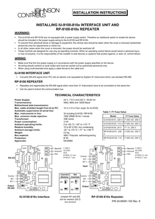
- 1. P/N 24-85481-102 Rev. E INSTALLATION INSTRUCTIONS INSTALLING IU-9100-810x INTERFACE UNIT AND RP-9100-810x REPEATER WARNING: • The IU-9100 and RP-9100 are not equipped with a power supply switch. Therefore an additional switch to isolate the device should be included in the power supply wiring to the IU-9100 and RP-9100. • To prevent from electrical shock or damage to equipment, the utmost care should be taken when the cover is removed (authorized personnel only) for adjustments or check out. • In all other cases when the cover is removed, the power should be switched off. • These Controls are designed for use only as operating Controls. When an operating control failure would result in personal injury or loss of property, it is the responsibility of the installer to add devices or systems that protect against, or warn of, control failure. WIRING: • Make sure that the line power supply is in accordance with the power supply specified on the device. • All wiring should conform to local codes and must be carried out by authorized personnel only. • When using multi-stranded wire apply a cable ferrule to the cable end. IU-9100 INTERFACE UNIT • Converts RS-232 signal (from PC) into an electric one requested by System 91 Instrument which use standard RS-485. RP-9100 REPEATER • Repeates and regenerates the RS-485 signal when more than 31 Instruments have to be connected on the same line. • Can be used to branch the communication bus TECHNICAL CHARACTERISTICS Power Supply: 24 V, 110 V and 230 V ; 50-60 Hz Transmissions: 4800, 9600 and 19200 Baud Bidirectional data transmission: Max. cable shielded length from IU to PC: 10 m (1,5 m Fact. suppl. for IU-9100) Automatic supervision of serial line: Max. instruments in line: 32 including IU-9100 / RP-9100 Max. common mode rejection: 1500 VRMS 50 Hz 1 minute Transformer: VDE norms Power consumption: 3 VA Ambient operating limits: 0 to +55 °C / +32° to +131 °F Relative humidity: 10 to 90 % RH, non condensing Ambient storage limits: -25 ° to +70 °C / -77 ° to +158 °F Weight: 0,5 kg Box material: ABS / Polycarb. self-extinguishing Protection: IP 30 Approvals: EN 60950 CABLE GLAND PG9 Ø MIN 4,5 mm Ø MAX 7 mm RS-232 Output RS-485 Hot Ground Neutral RT + RT - Comm. IU-9100-810x Interface W2 1 2 3 W1 3 2 1 Input Output Hot Ground Neutral RT + RT - Comm. RP-9100-810x Repeater W2 1 2 3 RT + RT - Comm. Inserted (factory) Not Inserted W1 W1 W2 W2 Jumpers W1 and W2 are for resistor 220 Ω line terminal 3 2 1 1 2 3 3 2 1 1 2 3 Table 1: F1 Fuse Value Model F1 Fuse Value IU-9100-8101, 230 V F 200 mA 250 V IU-9100-8103, 110 V F 400 mA 250 V IU-9100-8104, 24 V F 1 A 250 V RP-9100-8101, 230 V F 200 mA 250 V RP-9100-8103, 110 V F 400 mA 250 V CABLE GLAND PG9 Ø MIN 4,5 mm Ø MAX 7 mm
- 2. P/N 24-85481-102 Rev. E INSTALLATION INSTRUCTIONS RS485 BUS CONNECTION UP TO 32 UNITS IMPORTANT: Terminate the line with resistor 220 Ω on both lines end. Change Jumper W2 position inside the IU-9100 to disconnect line resistor. RS485 BUS CONNECTION WITH MORE THAN 32 UNITS IMPORTANT: Jumpers W1 and W2 for 220 Ω resistor line terminal are already factory positioned on the repeater RP-9100. The 220 Ω resistor of line termination is the optimal value verified with IU-9100 / RP-9100 line length for general applications. If the resistor terminal has to be optimized with line impedance, position Jumpers W1 and W2 in position of disinserted resistor and apply preferred resistor value. CONNECTION TABLES IU-9100 INTERFACE TO PC AND SYSTEM 91 CONTROLLERS RS-485 line maximum length without repeaters: 1200 meters RS-232C line maximum length: 10 meters RT+ RT- COM RP-9100 RX TX Com 0 IU-9100 Personal Computer Com 0 TO RS 485 RS 232 RX TX CD RX TX DTR RI S.GND DSR RTS CTS 6 5 3 1 1 2 3 4 9 5 6 7 8 shield S.GND RX TX 9 Poles IU-9100 9 Poles PC AT + - c + - c + - c 220 Ω Resistor for bus line termination IU-9100 1 32 max. COM RT + RT - 2 + - c + - c + - c IU-9100 1 31 COM RT + RT - 2 + - c 1 COM RT + RT - 32 max 220 Ω Resistor for bus line termination PC/IU 9100 CONNECTION WIRING DIAGRAMS PC/IU CABLE
- 3. P/N 24-85481-102 Rev. E INSTALLATION INSTRUCTIONS Max. quantity of instruments in line: 32 incl. IU-9100 / RP-9100