SlideShare a Scribd company logo
1 of 15
Download to read offline
Module 1: I C Engines
The engines in which the combustion of fuel takes place inside the engine cylinder are called
internal combustion engines. An Internal combustion engine more probably called as IC
Engine, is a heat engine which converts heat energy released by the combustion of fuel taking
place inside the engine cylinder into mechanical work. It has advantages such as high
efficiency, light weight, compactness, easy starting, adaptability, suitability for mobile
applications, comparatively lower initial cost has made its use as a prime mover.
IC Engine Terminology:
1.Stroke: It is the distance travelled by the piston from the cover end to the crank end or
from crank end to the cover end. It is denoted by L.
2. Bore: It is the diameter of the cylinder or outer diameter of the piston. It is denoted by D.
3. Top dead centre (TDC) or cover end: It is the extreme position of the piston, when the
piston is near cylinder head.
4. Bottom dead centre (BDC) or crank end: It is the extreme position of the piston, when
the piston is near the crankshaft end.
5. Swept volume (Vs): It is the volume covered by the piston when the piston moves from
TDC to BDC. It is denoted by Vs and is given by
Vs = (πD2
L /4)
6. Clearance volume (Vc): It is the volume occupied by the charge at the end of
compression stroke when the piston is at TDC.
7. Piston and Piston rings: Piston is a cylindrical part which reciprocates inside the cylinder
and is used for doing work and getting work. Piston has piston rings tightly fitted in groove
around piston and provide a tight seal so as to prevent leakage across piston and cylinder wall
during piston’s reciprocating motion. Pistons are manufactured by casting or forging process.
Pistons are made of cast iron, aluminium alloy. Piston rings are made of silicon, cast iron,
steel alloy by casting process.
8. Combustion space: It is the space available between the cylinder head and top of piston
when piston is at farthest position from crankshaft (TDC).
9. Intake manifold: It is the passage/duct connecting intake system to the inlet valve upon
cylinder. Through intake manifold the air/air-fuel mixture goes into cylinder.
10. Exhaust manifold: It is the passage/duct connecting exhaust system to the exhaust valve
upon cylinder. Through exhaust manifold burnt gases go out of cylinder.
11. Valves: Engine has both intake and exhaust type of valves which are operated by valve
operating mechanism comprising of cam, camshaft, follower, valve rod, rocker arm, valve
spring etc. Valves are generally of spring loaded type and made out of special alloy steels by
forging process.
12. Spark plug: It is the external ignitor used for initiating combustion process. Spark plug is
activated by electrical energy fed by electrical system with engine. It delivers spark with
suitable energy to initiate combustion at appropriate time for suitable duration.
13. Connecting rod: It is the member connecting piston and crankshaft. It has generally I
section and is made of steel by forging process.
14. Crank: It is the rigid member connecting the crankshaft and connecting rod. Crank is
mounted on crankshaft. Crank transfers motion from connecting rod to crankshaft as it is
linked to connecting rod through crank pin.
15. Crankshaft: It is the shaft at which useful positive work is available from the
piston-cylinder arrangement. Reciprocating motion of piston gets converted into rotary
motion of crankshaft. Crankshaft are manufactured by forging process from alloy steel.
16. Crankcase: Crankcase actually acts like a sump housing crank, crankshaft, connecting
rod and is attached to cylinder. These are made of aluminium alloy, steel, cast iron etc. by
casting process.
17. Gudgeon pin: It is the pin joining small end of the connecting rod and piston. This is
made of steel by forging process.
18. Bore: It is nominal inner diameter of the cylinder.
19. Piston area: It is the area of a circle of diameter equal to bore.
20. Stroke: It is the nominal distance travelled by the piston between two extreme positions
in the cylinder.
CLASSIFICATION OF IC ENGINES:
Internal combustion engines can be classified on the following basis.
(a) Based on number of strokes : Number of strokes involved in a cycle of IC engine can be
two strokes or four strokes. Such engine can be;
(i) Two stroke engines
(ii) Four stroke engines
(b) Based on thermodynamic cycle : Depending upon thermodynamic cycle used in the
internal combustion engines these can be classified as:
(i) Engines based on Otto cycle (‘Spark-Ignition engine’)
(ii) Engines based on Diesel or Dual cycle (‘Compression-Ignition engine’)
(c) Based on mechanism of ignition: Internal combustion engines have combustion as the
basic process. Combustion process may be initiated using externally assisted ignition (spark
ignition) or it may get initiated on its’ own due to excessive compression (compression
ignition). Such engines are called:
(i) Spark ignition engines
(ii) Compression ignition engines.
The spark ignition engines may have “magneto ignition system” or “battery ignition system”
for creating necessary electric potential for producing spark.
(d) Based on type of fuel used: IC engines may be classified depending upon the type of fuel
being used. These can be:
(i) Petrol engines (petrol being used as fuel)
(ii) Gas engines (gaseous fuel being used)
(iii) Diesel engines (diesel being used as fuel)
(iv) Multi-fuel engines (more than one fuel being used)
(e) Based on fuel admission: IC engines can be of different types depending upon
arrangement used for fuel admission:
(i) Carburettor type engines (use carburettor fuel metering)
(ii) Injection type engines (use fuel injector and injection system)
(f) Based on type of cooling: IC engines have inherent requirement of continuous cooling of
engine.
Based on type of cooling these can be classified as:
(i) Air cooled engines (Generally used in small sized engines)
(ii) Water cooled engines (Generally used in large sized engines)
(g) Based on type of motion: IC engines may have reciprocating motion of piston or it may
also have rotary motion. Such engines can be:
(i) Reciprocating engines
(ii) Rotary engines
Reciprocating engines may have different cylinder arrangements such as:
(i) Opposed cylinder engines
(ii) Inclined cylinder engines
(iii) V-shaped cylinder arrangement.
Rotary engines may be further classified as single rotor engines or multi rotor engines i.e.
(i) Single rotor engine (ii) Multi rotor engine
Combustion in SI Engines:
Combustion process in spark ignition engine has requirement of the ‘mixture of fuel
and air in right proportion,’ ‘mechanism for initiation of combustion process’ and
‘stabilization and propagation of flame for complete burning.’
For complete combustion of every fuel there is chemically correct fuel-air ratio also called
Stoichiometric fuel-air ratio. This fuel air ratio may be rich or lean depending upon the
proportion of fuel and air present in mixture. In SI engine this fuel air ratio generally varies
between 1 : 7 to 1 : 30 with lean mixture at 1 : 30 and rich mixture at 1 : 7. Stoichiometric
fuel-air ratio is around 1 : 14 to 1 : 15. The ratio of actual fuel-air ratio to Stoichiometric
fuel-air ratio is given by ‘equivalence ratio’ or ‘relative fuel-air ratio’. Appropriate fuel-air
ratio is maintained in SI engines through ‘carburettor’ (the fuel metering system).
Combustion in SI engine may be described to be occurring in following significant phase:
(i) After compression of fuel-air mixture in cylinder the high temperature spark is delivered
by spark plug in the compressed fuel-air mixture. Temperature at the tip of spark plug
electrode may go even more than 10,000ÂşC at the time of release of spark. Sparkles released
have sufficiently high temperature to initiate the combustion of fuel. After setting up of
combustion a sustainable flame front or flame nuclei is needed so that it proceeds across the
combustion space to ensure complete combustion. Thus, this phase in which spark is first
released followed by setting up of sustainable flame front is called “preparation phase”.
Crank angle rotation consumed in “preparation phase” depends upon the speed of engine,
constructional feature of cylinder, piston, location of spark plug, strength of spark,
characteristics of fuel, fuel-air ratio etc. Preparation phase is shown to occur from ‘a’ to ‘b’
with small or negligible pressure rise as initially rate of burning is very small.
(ii) After sustainable combustion flame is set up then the flame nuclei get scattered
due to excessive turbulence in combustion space causing pressure to rise from ‘b’
to ‘c’. This phase of combustion depends upon the turbulence inside cylinder,
strength of combustion nuclei, fuel-air ratio, strength of spark, cylinder geometry,
fuel properties etc. This phase of combustion is called as “flame propagation
phase” and is accompanied by the excessive pressure rise. Flame propagation
phase should also be as small as possible.
(iii) After the maximum amount of fuel-air mixture is burnt, the residual gets burnt
after the piston has moved across the TDC. This last phase is termed as “after
burning phase” and occurs during the expansion stroke.
Hence, it can be summarised that the complete combustion in SI engine occurs in three
distinct zones i.e. preparation phase, flame propagation phase and after burning phase. In
order to complete combustion in smallest possible time the flame propagation phase and
preparation phase should be shortened. It is seen that out of total distance travelled in
combustion space in first phase i.e. preparation phase about 10% of combustion space
length is covered in about 20–30% of total time for combustion. Flame propagation phase is
spread in about 80% of combustion space length and is covered in 60–70% of total time of
combustion. ‘After burning’ occurs in less than 10% of combustion space in less than 10% of
total combustion time.
Combustion in CI Engine:
In CI engine the fuel is injected into combustion space after the compression of air is
completed. Due to excessively high temperature and pressure of air the fuel when injected in
atomised form gets burnt on its’ own and burning of fuel is continued till the fuel is injected.
Different significant phases of combustion are explained as under:
(i) Injection of fuel in atomized form is initiated into the combustion space containing
compressed air. Fuel upon injection does not get burnt immediately instead some time is
required for preparation before start of combustion. Fuel droplet injected into high
temperature air first gets transformed into vapour (gaseous form) and then gets enveloped
around by suitable amount of oxygen present so as to form combustible mixture. Thus, the
delay in start of ignition may be said to occur due to ‘physical delay’ i.e. time consumed in
transformation from liquid droplet into gaseous form, and ‘chemical delay’ i.e. time
consumed in preparation for setting up of chemical reaction (combustion). Ignition delay is
shown by a – b. Fuel injection begins at ‘a’ and ignition begins at ‘b’. Theoretically, this
ignition delay should be as small as possible.
ii)For the duration in which preparation for ignition is made, the continuous fuel injection
results in accumulation of fuel in combustion space. The moment when ignition just begins, if
the sustainable flame front is established then this accumulated fuel also gets burnt rapidly.
This burning of accumulated fuel occurs in such a manner that combustion process becomes
uncontrolled resulting into steep pressure rise as shown from ‘b’ to ‘c’. The uncontrolled
burning continues till the collected fuel gets burnt. During this ‘uncontrolled combustion’
phase if the pressure rise is very abrupt then combustion is termed as ‘abnormal combustion’
and may even lead to damage of engine parts in extreme conditions. Thus, it is obvious that
‘uncontrolled combustion’ depends upon the ‘ignition delay’ period as during ignition delay
itself the accumulation of unburnt fuel occurs and its’ burning results in steep pressure rise.
Hence in order to have minimum uncontrolled combustion the ignition delay should be as
small as possible.
(iii) After the ‘uncontrolled combustion’ is over then the rate of burning matches with rate of
fuel injection and the combustion is termed as ‘controlled combustion’. Controlled
combustion is shown between ‘c’ to ‘d’ and during this phase maximum of heat gets evolved
in controlled manner. In controlled combustion phase rate of combustion can be directly
regulated by the rate of fuel injection i.e. through fuel injector.
(iv) After controlled combustion, the residual if any gets burnt and the combustion is termed
as ‘after burning’. This after burning may be there due to fuel particles residing in remote
position in combustion space where flame front could not reach.
Detonation / knocking:
“Abnormal combustion” is said to occur when combustion begins inside the cylinder on its’
own before the stipulated time for it. This abnormal combustion may be due to pre ignition
(i.e. ignition of fuel even before spark plug ignites it) and results in uncontrolled pressure
rise. Abnormal combustion is also termed as detonation or knocking and can be felt by jerky
operation of engine, excessive noise, reduced power output, excessive vibrations, excessive
heat release, pitting of cylinder head and piston head etc.
If the temperature of the unburnt mixture exceeds the self ignition temperature of the
fuel and remains at or above this temperature during the period of pre flame
reactions(ignition lag),spontaneous ignition or auto ignition occurs at various pin point
locations. This phenomenon is called knocking.
Factors affecting Detonation:
Design Parameters:
1) Compression ratio: Increase in CR increases thermal efficiency but also increases the
tendency to knock - limits engine performance.
2) Combustion chamber size and shape: As combustion chamber volume gets smaller,
“surface area-to-volume” ratio increases providing efficient cooling reduces tendency to
knock. In SI-engines max piston diameter is limited to 150 mm Flame propagation distance
(chamber shape and spark plug location, number of spark plugs used) also affects knocks
3) Valve overlap: It reduces residual gases, produces cooling effect - reduces knock tendency
4) Engine cooling: Efficient cooling reduces tendency to knock - water cooling systems are
more effective, in air-cooled engines compression ratio is limited
Operating Parameters:
1) Spark advance: Increasing spark advance, pressure and temperature increases, flame
speed also increases reducing the time for pre-reactions, but tendency to knock
increases with increasing spark advance.
2) Engine speed :Turbulence intensity increases - flame propagation increases,
volumetric efficiency is reduced and induction pressure is reduced, tendency to knock
decreases with increase in engine speed (rpm)
3) Oxygen concentration: In combustion chamber decreasing oxygen concentration
reduces the tendency to knock humidity of intake air also cools the charge and
reduces knocking tendency.
4) Cooling water temperature: Cooling water temperature effects mean combustion
chamber temperatures - tendency to knock decreases with decrease in temperature.
Injection quantity (load):
Reducing engine load changes Air fuel ratio, cools down the engine, reduces wall
temperatures, reduces residual gas temperatures and increases Ignition delay
Fuel Factors:
• The auto-ignition process depends on the fuel chemistry.
• Practical fuels are blends of a large number of individual hydrocarbon compounds, each of
which has its own chemical behaviour.
• A practical measure of a fuel’s resistance to knock is the octane number.
• High octane number fuels are more resistant to knock
•
Performance Analysis of IC-Engines:
Engine performance is an indication of the degree of success with which it does its assigned
job. i.e. conversion of chemical energy contained in the fuel into the useful mechanical work.
1) Indicated Power:
The total power developed by combustion of fuel in the combustion chamber is called
indicated power.
IP=PimLANk/60000 (KW)
Where,
k = Number of cylinders,
Pim = Indicated mean effective pressure in Pa or N/m2
,
L = Stroke length in m,
A = Area of piston, m2
, and
n = number of explosions per minute
= N/2 for 4-stroke engine,
= N for 2-stroke engine,
N = engine speed, rpm.
2) Brake Power:
The power developed by an engine at the output shaft is called the brake power.
BP=2ΠNT/60000 (KW)
Where,
T = torque, N-m.
N =engine speed, rpm.
3) Frictional Power:
FP=IP-BP
4) Mechanical Efficiency:
The ratio of Brake Power (B.P.) to Indicated Power (I.P.) is called mechanical efficiency.
Ρ =BP/IP
5) Thermal Efficiency:
It is the ratio of power output to energy supplied by the combustion of fuel.
Ρith =IP/Energy supplied =IP/mf*CV
Ρbth =BP/Energy supplied =BP/mf*CV
mf =Mass or volume flow rate of fuel in kg/s or m3
/s
CV =Calorific value of fule in KJ/Kg or KJ/m3
.
6) Relative Efficiency or Efficiency Ratio:
It is the ratio of actual efficiency of the engine to theoretical efficiency.
ΡR=Ρactual /Ρtheoritical
7) Volumetric Efficiency :
It is the ratio of actual the actual mass of air inducted by the engine during the suction
stroke to the theoretical mass of air that have been inducted by filling the piston displacement
volume with air at atmospheric temperature and pressure.
ΡV =mactual /mtheoritical
8) Mean effective pressure (Pm):
Mean effective pressure is defined as hypothetical pressure which is thought to be
acting on the piston throughout the power stroke.
Pm = (s × a)/l
a= Area of actual indicator diagram in m2
l= base width of indicator diagram in m
s= spring value of the spring used in the indicator in bar/m.
9) Specific Fuel Consumption (SFC):
It is the amount of fuel consumed per hour per unit power developed.
BSFC=mf /BP (Kg/KW-hr)
ISFC= mf /IP (Kg/KW-hr)
10) Air Fuel Ratio (A/F):
It is the ratio of the mass of the air to the mass of the fuel in the air-fuel mixture.
Relative air-fuel ratio is defined as the ratio of the actual air-fuel ratio to that of
Stoichiometric air- fuel ratio required to burn the fuel supplied
A/F= ma /mf
11) Specific output:
It is the brake power developed per unit volume of piston displacement
Specific ouput=BP/A*L
Heat Balance Sheet:
The performance of an engine is generally given by heat balance sheet.
To draw the heat balance sheet for I.C. engine, it should run at constant load till it attains
steady state and the following readings are noted.
Indicated mean effective pressure is calculated from an indicator diagram drawn with the
help of an engine indicator.
Heat Supplied kJ/s
or
kJ/min
or
kJ/hr
% Heat Utilized kJ/s
or
kJ/min
or
kJ/hr
%
Heat supplied by fuel a) Heat equivalent of BP, QA
b) Heat lost to cooling water, QB
c) Heat lost to exhaust gases, QC
d) Unaccounted heat loss, QD
Total, Qsupplied 10
0
Q utilized 10
0
Heat supplied by fuel: Q Supplied
For petrol and oil engines
QS = mf *CV
a) Heat equivalent of BP, (QA)=BP
b) Heat lost to cooling water, (QB) =mw*Cpw(To-Ti)
Where,
mw = mass of cooling water used in kg/s or kg/min or kg/hr.
Twi = Inlet temperature of cooling water.
Two = outlet temperature of cooling water.
Cpw = Specific heat of water.
c) Heat lost to exhaust gases,(QC) =mg*Cpg(Te –Ta)
Where,
mg = ma + mf
=mass of exhaust gases in kg/s or kg/min or kg/hr,
ma = mass of air supplied in kg/s or kg/min or kg/hr,
mf = mass of fuel supplied in kg/s or kg/min or kg/hr.
Ta = room temperature,
Te = temperature of exhaust gases,
Cpg = mean specific heat of exhaust gas at constant pressure,
d) Unaccounted heat loss = Q supplied-(QA+QB+QC)
Morse Test:
In IC engines there are three powers namely ‘indicated power’ which is developed
inside cylinder, ‘brake power’ which is available at crank shaft and ‘friction power’ which is
lost in overcoming friction and other losses. Brake power can be measured by using
dynamometer at the crank shaft of engine. Friction power can be experimentally determined
by number of methods namely ‘Willan’s line method’, ‘Motoring test’ and by the numerical
difference between indicated power and brake power.
• Morse test is used to find the Indicated Power and Friction power of a multi cylinder
engine.
• The engine is run at the required speed and the torque is measured using
dynamometer.
• The Brake Power BP is determined.
• Now one cylinder is cut-off by shorting the spark plug (S.I. engine) or by
disconnecting fuel injector (C.I. engine).
• The engine speed falls because of the loss of power with one cylinder cut-off, but is
restored by reducing the load.
• The torque is measured again when the speed has reached its original value.
• The Brake Power BP1 is determined.
• The first cylinder is restored and second cylinder is cut off.
• The engine speed will again vary. By adjusting the load, the engine speed is again
brought to original speed.
• The Brake Power BP2 is determined.
• Same procedure is followed till the last cylinder is cut off.
Assume a four cylinder engine.
Let IP1, IP2, IP3 and IP4 be the indicated power of individual cylinders.
Also FP1, FP2, FP3 and FP4 be the friction power of individual cylinders.
When all the cylinders are working,
Total BP = BP1+BP2+BP3+BP4
=(IP1- FP1)+(IP2- FP2)+(IP3- FP3)+(IP4- FP4)
=(IP1+IP2+IP3+IP4)-(FP1+FP2+FP3+FP4) -------(1)
When first cylinder is cut off,
BP1= (IP2+IP3+IP4)-(FP1+FP2+FP3+FP4) --------------- (2)
Eq. (1)-(2),
BP-BP1= IP1
Similarly,
BP-BP2= IP2
BP-BP3= IP3
BP-BP4= IP4
Willan’s line method:
At a constant engine speed the load is reduced in increments and the corresponding B.P. and
gross fuel consumption are taken.
A graph is then drawn of fuel consumption against B.P. as in Fig.
The graph drawn is called Willan’s line and is extrapolated back to cut the B.P. axis at the
point L. The reading OL is taken as the power loss of the engine at that speed.
The fuel consumption at zero B.P. is given by OM; and if the relationship between fuel
consumption and B.P. is assumed to be linear, then a fuel consumption OM is equivalent to a
power loss of OL.
This method is used only in case of unthrottled engines as discussed below:
The Willan’s line is plotted for fuel consumption versus load at constant speed.
The intersection of this line on the negative side of X-axis gives the Friction Power of the
engine at that speed.
The friction power (F.P.) is assumed constant from no load to full load at that constant speed.
The F.P. includes not only the mechanical friction, but also the pumping power.
Motoring test:
In this test the engine is first run up to the desired speed by its own power and allowed to
remain under the given speed and load conditions for some time so that oil, water and engine
component temperature reach stable conditions.
The power of the engine during this period is absorbed by a dynamometer.
The fuel supply is then cut-off and by suitable electric switching devices the dynamometer is
converted to run as motor to drive or ‘motor’ the engine at the same speed at which it was
previously running.
The power supply to the motor is measured which is a measure of F.P. of the engine.
Motoring test gives a very good insight into the various causes of losses and is much more
powerful tool. This test gives a higher value of F.P. as compared to that given by Willan’s
line method.
IC Engine Fuels:
Fuels used in SI engines and CI engines are different as the nature of combustion
process is different in the two engines. Normally hydrocarbon fuels are used for both the
applications and should possess desirable properties such as high calorific value, suitable
combustion characteristics, ease of handling, environment friendly etc. In SI engines the fuel
used is generally ‘gasoline’ also called as petrol and is mixture of different hydrocarbons.
SI engine fuels are characterised in respect to its’ resistance to abnormal combustion by its’
rating in terms of “Octane number”. Octane number of fuel is determined by comparing the
combustion performance of actual fuel with that of reference fuel. Octane number is defined
as the percentage by volume of iso-octane in a mixture of iso-octane and n-heptane. Iso
octane is low boiling point fuel having very high resistance to abnormal combustion and is
arbitrarily assigned octane number of 100. ‘n-heptane’ is seen to have very poor resistance to
abnormal combustion and is so assigned octane number of 0. The composition of iso-octane
fraction and n-heptane fraction which yields the similar combustion characteristics is used to
know the octane number. Say, for example in a particular test the mixture of 80% by volume
of iso-octane and 20% by volume of n -heptane offers the combustion similar to that of test
fuel. Then the test fuel shall have octane number of 80. Octane number generally lies
between 0 and 100 but can be extended beyond 100 by using certain additives. ‘Tetra ethyl
lead’ is the most popular additive used in SI engines which further increases resistance to
abnormal combustion.
In CI engines the Diesel fuel is generally used which is also available during petroleum
refining but is impure as compared to SI engine fuel. CI engine fuels are also characterized
by a rating given in terms of ‘Cetane number’ which also indicates the resistance of fuel to
knocking. Cetane number for any fuel is given by percentage by volume of Cetane in a
mixture of Cetane and Îą-methyl naphthalene which offers the combustion characteristics
similar to that of test fuel.
Cetane is arbitrarily assigned Cetane number of 100 as it offers maximum knock resistance
and Îą-methyl naphthalene is assigned Cetane number of 0 as it has minimum knock
resistance.
Ratings and Alternate Fuels:
Generally fuels rating are given for their antiknock qualities. The rating of fuels is
done by defining two parameters called Octane number and Cetane number for gasoline
and diesel oil respectively.
Rating of SI Engine Fuels:
Resistance to knocking is an extremely important characteristic of fuel for spark-ignition
(SI) engines. These fuels differ widely in their ability to resist knock depending on their
chemical composition. In addition to the chemical characteristics of hydrocarbons in the fuel,
other operating parameters such as engine speed, fuel-air ratio, ignition timing, shape of the
combustion chamber, compression ratio, ambient conditions, etc. affect the tendency to knock
in the engine cylinder. Therefore, in order to determine the knock resistance characteristic of
the fuels, the SI engine and its operating variables must be fixed at standard values.
According to a standard practice, the antiknock value of an SI engine fuel is
determined by comparing its antiknock property with a mixture of two reference fuels,
normal heptane (C7H18) and iso-octane (C8H18). Iso-octane chemically being a very good
antiknock fuel, is arbitrarily assigned a rating of 100 octane number. Normal heptane (C7H16)
has very poor antiknock qualities and is a given a rating of 0 octane number. The addition of
certain compounds (e.g. tetraethyl lead) to iso-octane produces fuels of greater antiknock
quality. The antiknock effectiveness of tetraethyl lead, for the same quantity of fuel added,
decreases as the total content of the lead in the fuel increases. Further, each octane number at
high range of the octane scale will produce greater antiknock effect compared to the same
unit at the lower end of the scale.
Octane number can be computed with Performance Number (PN) by using the formula
Ratings of CI Engine Fuels:
The knock rating of a diesel fuel is found by comparing the fuel under prescribed
conditions of operation in a special engine with primary reference fuels. The reference fuels
are normal Cetane (C16H34), which is arbitrarily assigned a Cetane number of 100 and
Îą-methyl naphthalene (C11H10) with an assigned Cetane number of 0. Cetane number of a fuel
is defined as the percentage by volume of normal Cetane in a mixture of normal Cetane and
Îą-methyl naphthalene which has the same ignition characteristics (ignition delay) as the test
fuel when combustion is carried out in a standard engine under specified operating
conditions. Since ignition delay is the primary factor in controlling the initial auto ignition in
CI engine, it is reasonable to conclude that knock should be directly related to the ignition
delay of the fuel. Knock resistance property of diesel oil can be improved by adding small
quantities of compounds like amyl nitrate, ethyl nitrate or ether.
Alternate Fuels:
The rapid depletion of fossil fuels and ever increasing price of crude oil made the
researchers to search for alternative source of energy. The scarcity of known petroleum
reserves will make renewable energy resources more attractive. The most feasible way to
meet this growing demand is by utilizing alternative fuels.
In mid 1970, ethanol and methanol were considered as prime alternative to diesel and the
most promising techniques are explored for better engine performance namely power output,
thermal efficiency, emissions and operability.
Alcohol as IC Engine Fuel :
Many countries like Brazil, Mauritius, US and few European countries are using ethanol
blended fuel in automobiles. Ethanol is produced from sugar molasses, wood, maize, beet
etc,. Ethanol is processed from any feed stock such as corn, wheat, sugar cane, tapioca and
other grains. Methanol is produced from coal, natural gas, farm waste, municipal waste etc., The
municipal wastes are first shredded and then passed under a magnet to remove the ferrous materials
and then gasified with oxygen.
Edible Vegetable Oil:
In 1911 itself, Rudolf Diesel demonstrated his engine with peanut oil and said that the
diesel engine can be fed with vegetable oils and would help considerably in the development
of agriculture of the countries which use it.
Initially, it was believed that vegetable oils could be used directly with minimum processing
and preparation. Out of all the alternative fuels, vegetable oil offers an advantage because of
its comparable fuel properties with diesel and can be substituted between 20% to 100%
depending upon its processing. The various vegetable oils like sunflower oil, safflower oil,
soybean oil, rice bran oil, palm oil, peanut oil, cotton seed oil etc. have been tested in the
diesel engine.
The vegetable oil fuel has gained importance due to the following merits :
* It has high Cetane number
* It is renewable
* It is carbon neutral
* It can be abundantly produced at low cost
* It is not harmful to engine
* It is eco friendly
* It aims at reduction in crude import
Non-Edible Vegetable Oil :
If an oil contains aflatoxin contents of pesticides, carcinogenic substances and toxic
metal concentration, the oil is labeled as non edible oil. There are several non edible oils such
as Jatropha, pongamia oil, madhuca indica, mango seed oil, tobacco seed oil on which the
research as alternative fuel has gained momentum.
Biodiesel:
Biodiesel is a kind of fuel produced by a process known as Transesterification. This is
a process of transformation of one type of ester into another type of ester. Vegetable oil is a
triglyceride. The biggest advantage that biodiesel has over gasoline and petroleum diesel is its
environmental friendliness. The higher heating values of biodiesels are closer to that of the
petroleum products in the range of 39–41 MJ/kg.
Biodiesel burns similar to petroleum diesel as it concerns regulated pollutants. On the
other hand, biodiesel probably has better efficiency than gasoline. Important operating
disadvantages of biodiesel in comparison with petro diesel are cold start problems, the lower
energy content, higher copper strip corrosion and fuel pumping difficulty from higher
viscosity.
The use of 20% biodiesel when mixed with 80% diesel reduces 13.1% CO emission
when compared to engine running with diesel, SO2 emission reduces to 20%, particulate
matter reduces to 8.9%, volatile matter reduces to 17.9% with the increase in 2.4% NOx
emission. When the engine was run with pure biodiesel (i.e. 100% biodiesel) there was 42.7%
drop in CO emission, no SO2 emission at all, drop in particulate matter up to 55.3%, the
volatile organic compounds drops to 63.2% with 13.2% increase in NOx emission. Hence the
use of biodiesel increases NOx emission with the drop in all the remaining pollutants.
The use of biodiesel gives the following advantages:
- It can be used in any conventional, unmodified diesel engines
- It can be used alone or mixed in any amount with diesel fuel
-It has more lubrication than diesel, so it increases the life of engines
- It has higher Cetane number and higher biodegradability
- It is non toxic and it has higher combustion efficiency
-It has high flash point and hence safe to transport and store
- It is an oxygenated fuel and hence clean burning
-It is sulphur free and it reduces the dependency on imported petroleum
-It provides domestic, renewable energy
-It provides employment opportunities
Automotive Pollutions and its effects on environment:
When a automobile is running, several different types of gases and particles are
emitted that can have detrimental effects on the environment. Of particular concern to the
environment are carbon dioxide, a greenhouse gas; hydrocarbons -- any of more than a dozen
volatile organic compounds, some of which are known carcinogens; nitrogen oxides; sulphur
oxides; and particulate matter, tiny particles of solids, such as metal and soot. Other
emissions that affect human health and create smog include ozone and carbon monoxide.
The greenhouse gasses, such as carbon dioxide, methane, Nitrous oxide which
contributes to global warming. Some air pollutants and particulate matter from cars can be
deposited on soil and surface waters where they enter the food chain; these substances can
affect the reproductive, respiratory, immune and neurological systems of animals. Nitrogen
oxides and sulphur oxides are major contributors to acid rain, which changes the pH of
waterways and soils and can harm the organisms that rely on these resources.
The ozone layer helps to protect life on earth from the sun’s ultraviolet rays, but
human activities have contributed to the accelerated depletion of this protective shield.
Substances that contribute to ozone depletion usually have high concentrations of chlorine or
bromine atoms and include chlorofluorocarbons, or CFCs, halons, methyl bromide, carbon
tetrachloride and methyl chloroform. Vehicle emissions contain few chlorine- or
bromine-heavy substances, and therefore have little effect on ozone depletion.
Vehicles contain many different fluids, including motor oil, antifreeze, gasoline,
air-conditioning refrigerants, and brake, transmission, hydraulic and windshield-wiper fluids.
In most cases, these fluids are toxic to humans and animals, and can pollute waterways if they
leak from a vehicle or are disposed of incorrectly. Many vehicle fluids are exposed to heat
and oxygen while an engine is running, and undergo chemical changes.
The effects of car pollution are widespread, affecting air, soil and water quality.
Nitrous oxide contributes to the depletion of the ozone layer, which shields the Earth from
harmful ultraviolet radiation from the sun. Sulphur dioxide and nitrogen dioxide mix with
rainwater to create acid rain, which damages crops, forests and other vegetation and
buildings. Oil and fuel spills from cars and trucks seep into the soil near highways, and
discarded fuel and particulates from vehicle emissions contaminate lakes, rivers and
wetlands.

More Related Content

Similar to I C Engine.pdf

Internal combustion engines (1)
Internal combustion engines (1)Internal combustion engines (1)
Internal combustion engines (1)yallahemanthpaul
 
Reciprocating Internal Combustion Engine
Reciprocating Internal Combustion EngineReciprocating Internal Combustion Engine
Reciprocating Internal Combustion EngineMushtaqAhmedSulaiman
 
Basic of Combustion in CI Engines
Basic of Combustion in CI EnginesBasic of Combustion in CI Engines
Basic of Combustion in CI EnginesSACHINNikam39
 
Training report on Diesel Engine's component Engine head
Training report on Diesel Engine's component Engine headTraining report on Diesel Engine's component Engine head
Training report on Diesel Engine's component Engine headAbhishek Jakhar
 
Chapter 1 internal combustion engine
Chapter 1 internal combustion engineChapter 1 internal combustion engine
Chapter 1 internal combustion engineMuhd Taufik Muhammad
 
Lecture No. 02_ Engine.pdf
Lecture No. 02_ Engine.pdfLecture No. 02_ Engine.pdf
Lecture No. 02_ Engine.pdfHrBhupendra
 
IC engine-1.pptx
IC engine-1.pptxIC engine-1.pptx
IC engine-1.pptxSaqibShaik2
 
Ic engine final
Ic engine  finalIc engine  final
Ic engine finalSusandeep90
 
As introduction ic engine
As introduction ic engineAs introduction ic engine
As introduction ic enginesharmaabhi
 
i c eng 22.03.21 edited.ppt
i c eng 22.03.21 edited.ppti c eng 22.03.21 edited.ppt
i c eng 22.03.21 edited.pptMuthuG12
 
i c engine terminology
i c engine terminologyi c engine terminology
i c engine terminologyKrishna Gali
 
ME 6404 THERMAL ENGINEERING UNIT II
ME 6404 THERMAL ENGINEERING UNIT IIME 6404 THERMAL ENGINEERING UNIT II
ME 6404 THERMAL ENGINEERING UNIT IIBIBIN CHIDAMBARANATHAN
 
ic Engine and reciprocating machine ch1.pdf
ic Engine and reciprocating machine ch1.pdfic Engine and reciprocating machine ch1.pdf
ic Engine and reciprocating machine ch1.pdfTsegayePaulos1
 
different ic engine based vehicle types and working.pptx
different ic engine based vehicle types and working.pptxdifferent ic engine based vehicle types and working.pptx
different ic engine based vehicle types and working.pptxArnabChakraborty499766
 
IC Engines- 2 stroke and 4 stroke
IC Engines- 2 stroke and 4 strokeIC Engines- 2 stroke and 4 stroke
IC Engines- 2 stroke and 4 strokeShivam Kumar
 

Similar to I C Engine.pdf (20)

Internal combustion engines (1)
Internal combustion engines (1)Internal combustion engines (1)
Internal combustion engines (1)
 
Heat Engine
Heat Engine Heat Engine
Heat Engine
 
Reciprocating Internal Combustion Engine
Reciprocating Internal Combustion EngineReciprocating Internal Combustion Engine
Reciprocating Internal Combustion Engine
 
Basic of Combustion in CI Engines
Basic of Combustion in CI EnginesBasic of Combustion in CI Engines
Basic of Combustion in CI Engines
 
Training report on Diesel Engine's component Engine head
Training report on Diesel Engine's component Engine headTraining report on Diesel Engine's component Engine head
Training report on Diesel Engine's component Engine head
 
Study on IC Engine
Study on IC EngineStudy on IC Engine
Study on IC Engine
 
Chapter 1 internal combustion engine
Chapter 1 internal combustion engineChapter 1 internal combustion engine
Chapter 1 internal combustion engine
 
Lecture No. 02_ Engine.pdf
Lecture No. 02_ Engine.pdfLecture No. 02_ Engine.pdf
Lecture No. 02_ Engine.pdf
 
IC engine-1.pptx
IC engine-1.pptxIC engine-1.pptx
IC engine-1.pptx
 
UNIT 1.docx
UNIT 1.docxUNIT 1.docx
UNIT 1.docx
 
Ic engine final
Ic engine  finalIc engine  final
Ic engine final
 
Basics of ic engine
Basics of ic engine Basics of ic engine
Basics of ic engine
 
As introduction ic engine
As introduction ic engineAs introduction ic engine
As introduction ic engine
 
i c eng 22.03.21 edited.ppt
i c eng 22.03.21 edited.ppti c eng 22.03.21 edited.ppt
i c eng 22.03.21 edited.ppt
 
i c engine terminology
i c engine terminologyi c engine terminology
i c engine terminology
 
ME 6404 THERMAL ENGINEERING UNIT II
ME 6404 THERMAL ENGINEERING UNIT IIME 6404 THERMAL ENGINEERING UNIT II
ME 6404 THERMAL ENGINEERING UNIT II
 
ic Engine and reciprocating machine ch1.pdf
ic Engine and reciprocating machine ch1.pdfic Engine and reciprocating machine ch1.pdf
ic Engine and reciprocating machine ch1.pdf
 
different ic engine based vehicle types and working.pptx
different ic engine based vehicle types and working.pptxdifferent ic engine based vehicle types and working.pptx
different ic engine based vehicle types and working.pptx
 
Lab report
Lab report Lab report
Lab report
 
IC Engines- 2 stroke and 4 stroke
IC Engines- 2 stroke and 4 strokeIC Engines- 2 stroke and 4 stroke
IC Engines- 2 stroke and 4 stroke
 

Recently uploaded

College Call Girls Nashik Nehal 7001305949 Independent Escort Service Nashik
College Call Girls Nashik Nehal 7001305949 Independent Escort Service NashikCollege Call Girls Nashik Nehal 7001305949 Independent Escort Service Nashik
College Call Girls Nashik Nehal 7001305949 Independent Escort Service NashikCall Girls in Nagpur High Profile
 
(MEERA) Dapodi Call Girls Just Call 7001035870 [ Cash on Delivery ] Pune Escorts
(MEERA) Dapodi Call Girls Just Call 7001035870 [ Cash on Delivery ] Pune Escorts(MEERA) Dapodi Call Girls Just Call 7001035870 [ Cash on Delivery ] Pune Escorts
(MEERA) Dapodi Call Girls Just Call 7001035870 [ Cash on Delivery ] Pune Escortsranjana rawat
 
Application of Residue Theorem to evaluate real integrations.pptx
Application of Residue Theorem to evaluate real integrations.pptxApplication of Residue Theorem to evaluate real integrations.pptx
Application of Residue Theorem to evaluate real integrations.pptx959SahilShah
 
Microscopic Analysis of Ceramic Materials.pptx
Microscopic Analysis of Ceramic Materials.pptxMicroscopic Analysis of Ceramic Materials.pptx
Microscopic Analysis of Ceramic Materials.pptxpurnimasatapathy1234
 
HARMONY IN THE NATURE AND EXISTENCE - Unit-IV
HARMONY IN THE NATURE AND EXISTENCE - Unit-IVHARMONY IN THE NATURE AND EXISTENCE - Unit-IV
HARMONY IN THE NATURE AND EXISTENCE - Unit-IVRajaP95
 
CCS355 Neural Network & Deep Learning UNIT III notes and Question bank .pdf
CCS355 Neural Network & Deep Learning UNIT III notes and Question bank .pdfCCS355 Neural Network & Deep Learning UNIT III notes and Question bank .pdf
CCS355 Neural Network & Deep Learning UNIT III notes and Question bank .pdfAsst.prof M.Gokilavani
 
VIP Call Girls Service Hitech City Hyderabad Call +91-8250192130
VIP Call Girls Service Hitech City Hyderabad Call +91-8250192130VIP Call Girls Service Hitech City Hyderabad Call +91-8250192130
VIP Call Girls Service Hitech City Hyderabad Call +91-8250192130Suhani Kapoor
 
🔝9953056974🔝!!-YOUNG call girls in Rajendra Nagar Escort rvice Shot 2000 nigh...
🔝9953056974🔝!!-YOUNG call girls in Rajendra Nagar Escort rvice Shot 2000 nigh...🔝9953056974🔝!!-YOUNG call girls in Rajendra Nagar Escort rvice Shot 2000 nigh...
🔝9953056974🔝!!-YOUNG call girls in Rajendra Nagar Escort rvice Shot 2000 nigh...9953056974 Low Rate Call Girls In Saket, Delhi NCR
 
IVE Industry Focused Event - Defence Sector 2024
IVE Industry Focused Event - Defence Sector 2024IVE Industry Focused Event - Defence Sector 2024
IVE Industry Focused Event - Defence Sector 2024Mark Billinghurst
 
Oxy acetylene welding presentation note.
Oxy acetylene welding presentation note.Oxy acetylene welding presentation note.
Oxy acetylene welding presentation note.eptoze12
 
Architect Hassan Khalil Portfolio for 2024
Architect Hassan Khalil Portfolio for 2024Architect Hassan Khalil Portfolio for 2024
Architect Hassan Khalil Portfolio for 2024hassan khalil
 
Artificial-Intelligence-in-Electronics (K).pptx
Artificial-Intelligence-in-Electronics (K).pptxArtificial-Intelligence-in-Electronics (K).pptx
Artificial-Intelligence-in-Electronics (K).pptxbritheesh05
 
ZXCTN 5804 / ZTE PTN / ZTE POTN / ZTE 5804 PTN / ZTE POTN 5804 ( 100/200 GE Z...
ZXCTN 5804 / ZTE PTN / ZTE POTN / ZTE 5804 PTN / ZTE POTN 5804 ( 100/200 GE Z...ZXCTN 5804 / ZTE PTN / ZTE POTN / ZTE 5804 PTN / ZTE POTN 5804 ( 100/200 GE Z...
ZXCTN 5804 / ZTE PTN / ZTE POTN / ZTE 5804 PTN / ZTE POTN 5804 ( 100/200 GE Z...ZTE
 
Gurgaon ✡️9711147426✨Call In girls Gurgaon Sector 51 escort service
Gurgaon ✡️9711147426✨Call In girls Gurgaon Sector 51 escort serviceGurgaon ✡️9711147426✨Call In girls Gurgaon Sector 51 escort service
Gurgaon ✡️9711147426✨Call In girls Gurgaon Sector 51 escort servicejennyeacort
 
Model Call Girl in Narela Delhi reach out to us at 🔝8264348440🔝
Model Call Girl in Narela Delhi reach out to us at 🔝8264348440🔝Model Call Girl in Narela Delhi reach out to us at 🔝8264348440🔝
Model Call Girl in Narela Delhi reach out to us at 🔝8264348440🔝soniya singh
 
microprocessor 8085 and its interfacing
microprocessor 8085  and its interfacingmicroprocessor 8085  and its interfacing
microprocessor 8085 and its interfacingjaychoudhary37
 
High Profile Call Girls Nagpur Isha Call 7001035870 Meet With Nagpur Escorts
High Profile Call Girls Nagpur Isha Call 7001035870 Meet With Nagpur EscortsHigh Profile Call Girls Nagpur Isha Call 7001035870 Meet With Nagpur Escorts
High Profile Call Girls Nagpur Isha Call 7001035870 Meet With Nagpur Escortsranjana rawat
 
VICTOR MAESTRE RAMIREZ - Planetary Defender on NASA's Double Asteroid Redirec...
VICTOR MAESTRE RAMIREZ - Planetary Defender on NASA's Double Asteroid Redirec...VICTOR MAESTRE RAMIREZ - Planetary Defender on NASA's Double Asteroid Redirec...
VICTOR MAESTRE RAMIREZ - Planetary Defender on NASA's Double Asteroid Redirec...VICTOR MAESTRE RAMIREZ
 

Recently uploaded (20)

College Call Girls Nashik Nehal 7001305949 Independent Escort Service Nashik
College Call Girls Nashik Nehal 7001305949 Independent Escort Service NashikCollege Call Girls Nashik Nehal 7001305949 Independent Escort Service Nashik
College Call Girls Nashik Nehal 7001305949 Independent Escort Service Nashik
 
(MEERA) Dapodi Call Girls Just Call 7001035870 [ Cash on Delivery ] Pune Escorts
(MEERA) Dapodi Call Girls Just Call 7001035870 [ Cash on Delivery ] Pune Escorts(MEERA) Dapodi Call Girls Just Call 7001035870 [ Cash on Delivery ] Pune Escorts
(MEERA) Dapodi Call Girls Just Call 7001035870 [ Cash on Delivery ] Pune Escorts
 
Application of Residue Theorem to evaluate real integrations.pptx
Application of Residue Theorem to evaluate real integrations.pptxApplication of Residue Theorem to evaluate real integrations.pptx
Application of Residue Theorem to evaluate real integrations.pptx
 
Microscopic Analysis of Ceramic Materials.pptx
Microscopic Analysis of Ceramic Materials.pptxMicroscopic Analysis of Ceramic Materials.pptx
Microscopic Analysis of Ceramic Materials.pptx
 
HARMONY IN THE NATURE AND EXISTENCE - Unit-IV
HARMONY IN THE NATURE AND EXISTENCE - Unit-IVHARMONY IN THE NATURE AND EXISTENCE - Unit-IV
HARMONY IN THE NATURE AND EXISTENCE - Unit-IV
 
9953056974 Call Girls In South Ex, Escorts (Delhi) NCR.pdf
9953056974 Call Girls In South Ex, Escorts (Delhi) NCR.pdf9953056974 Call Girls In South Ex, Escorts (Delhi) NCR.pdf
9953056974 Call Girls In South Ex, Escorts (Delhi) NCR.pdf
 
CCS355 Neural Network & Deep Learning UNIT III notes and Question bank .pdf
CCS355 Neural Network & Deep Learning UNIT III notes and Question bank .pdfCCS355 Neural Network & Deep Learning UNIT III notes and Question bank .pdf
CCS355 Neural Network & Deep Learning UNIT III notes and Question bank .pdf
 
VIP Call Girls Service Hitech City Hyderabad Call +91-8250192130
VIP Call Girls Service Hitech City Hyderabad Call +91-8250192130VIP Call Girls Service Hitech City Hyderabad Call +91-8250192130
VIP Call Girls Service Hitech City Hyderabad Call +91-8250192130
 
🔝9953056974🔝!!-YOUNG call girls in Rajendra Nagar Escort rvice Shot 2000 nigh...
🔝9953056974🔝!!-YOUNG call girls in Rajendra Nagar Escort rvice Shot 2000 nigh...🔝9953056974🔝!!-YOUNG call girls in Rajendra Nagar Escort rvice Shot 2000 nigh...
🔝9953056974🔝!!-YOUNG call girls in Rajendra Nagar Escort rvice Shot 2000 nigh...
 
IVE Industry Focused Event - Defence Sector 2024
IVE Industry Focused Event - Defence Sector 2024IVE Industry Focused Event - Defence Sector 2024
IVE Industry Focused Event - Defence Sector 2024
 
Oxy acetylene welding presentation note.
Oxy acetylene welding presentation note.Oxy acetylene welding presentation note.
Oxy acetylene welding presentation note.
 
Architect Hassan Khalil Portfolio for 2024
Architect Hassan Khalil Portfolio for 2024Architect Hassan Khalil Portfolio for 2024
Architect Hassan Khalil Portfolio for 2024
 
Artificial-Intelligence-in-Electronics (K).pptx
Artificial-Intelligence-in-Electronics (K).pptxArtificial-Intelligence-in-Electronics (K).pptx
Artificial-Intelligence-in-Electronics (K).pptx
 
Call Us -/9953056974- Call Girls In Vikaspuri-/- Delhi NCR
Call Us -/9953056974- Call Girls In Vikaspuri-/- Delhi NCRCall Us -/9953056974- Call Girls In Vikaspuri-/- Delhi NCR
Call Us -/9953056974- Call Girls In Vikaspuri-/- Delhi NCR
 
ZXCTN 5804 / ZTE PTN / ZTE POTN / ZTE 5804 PTN / ZTE POTN 5804 ( 100/200 GE Z...
ZXCTN 5804 / ZTE PTN / ZTE POTN / ZTE 5804 PTN / ZTE POTN 5804 ( 100/200 GE Z...ZXCTN 5804 / ZTE PTN / ZTE POTN / ZTE 5804 PTN / ZTE POTN 5804 ( 100/200 GE Z...
ZXCTN 5804 / ZTE PTN / ZTE POTN / ZTE 5804 PTN / ZTE POTN 5804 ( 100/200 GE Z...
 
Gurgaon ✡️9711147426✨Call In girls Gurgaon Sector 51 escort service
Gurgaon ✡️9711147426✨Call In girls Gurgaon Sector 51 escort serviceGurgaon ✡️9711147426✨Call In girls Gurgaon Sector 51 escort service
Gurgaon ✡️9711147426✨Call In girls Gurgaon Sector 51 escort service
 
Model Call Girl in Narela Delhi reach out to us at 🔝8264348440🔝
Model Call Girl in Narela Delhi reach out to us at 🔝8264348440🔝Model Call Girl in Narela Delhi reach out to us at 🔝8264348440🔝
Model Call Girl in Narela Delhi reach out to us at 🔝8264348440🔝
 
microprocessor 8085 and its interfacing
microprocessor 8085  and its interfacingmicroprocessor 8085  and its interfacing
microprocessor 8085 and its interfacing
 
High Profile Call Girls Nagpur Isha Call 7001035870 Meet With Nagpur Escorts
High Profile Call Girls Nagpur Isha Call 7001035870 Meet With Nagpur EscortsHigh Profile Call Girls Nagpur Isha Call 7001035870 Meet With Nagpur Escorts
High Profile Call Girls Nagpur Isha Call 7001035870 Meet With Nagpur Escorts
 
VICTOR MAESTRE RAMIREZ - Planetary Defender on NASA's Double Asteroid Redirec...
VICTOR MAESTRE RAMIREZ - Planetary Defender on NASA's Double Asteroid Redirec...VICTOR MAESTRE RAMIREZ - Planetary Defender on NASA's Double Asteroid Redirec...
VICTOR MAESTRE RAMIREZ - Planetary Defender on NASA's Double Asteroid Redirec...
 

I C Engine.pdf

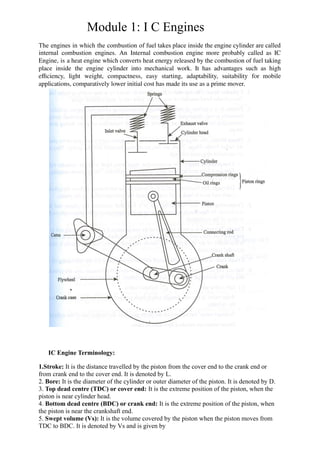
  • 1. Module 1: I C Engines The engines in which the combustion of fuel takes place inside the engine cylinder are called internal combustion engines. An Internal combustion engine more probably called as IC Engine, is a heat engine which converts heat energy released by the combustion of fuel taking place inside the engine cylinder into mechanical work. It has advantages such as high efficiency, light weight, compactness, easy starting, adaptability, suitability for mobile applications, comparatively lower initial cost has made its use as a prime mover. IC Engine Terminology: 1.Stroke: It is the distance travelled by the piston from the cover end to the crank end or from crank end to the cover end. It is denoted by L. 2. Bore: It is the diameter of the cylinder or outer diameter of the piston. It is denoted by D. 3. Top dead centre (TDC) or cover end: It is the extreme position of the piston, when the piston is near cylinder head. 4. Bottom dead centre (BDC) or crank end: It is the extreme position of the piston, when the piston is near the crankshaft end. 5. Swept volume (Vs): It is the volume covered by the piston when the piston moves from TDC to BDC. It is denoted by Vs and is given by
  • 2. Vs = (πD2 L /4) 6. Clearance volume (Vc): It is the volume occupied by the charge at the end of compression stroke when the piston is at TDC. 7. Piston and Piston rings: Piston is a cylindrical part which reciprocates inside the cylinder and is used for doing work and getting work. Piston has piston rings tightly fitted in groove around piston and provide a tight seal so as to prevent leakage across piston and cylinder wall during piston’s reciprocating motion. Pistons are manufactured by casting or forging process. Pistons are made of cast iron, aluminium alloy. Piston rings are made of silicon, cast iron, steel alloy by casting process. 8. Combustion space: It is the space available between the cylinder head and top of piston when piston is at farthest position from crankshaft (TDC). 9. Intake manifold: It is the passage/duct connecting intake system to the inlet valve upon cylinder. Through intake manifold the air/air-fuel mixture goes into cylinder. 10. Exhaust manifold: It is the passage/duct connecting exhaust system to the exhaust valve upon cylinder. Through exhaust manifold burnt gases go out of cylinder. 11. Valves: Engine has both intake and exhaust type of valves which are operated by valve operating mechanism comprising of cam, camshaft, follower, valve rod, rocker arm, valve spring etc. Valves are generally of spring loaded type and made out of special alloy steels by forging process. 12. Spark plug: It is the external ignitor used for initiating combustion process. Spark plug is activated by electrical energy fed by electrical system with engine. It delivers spark with suitable energy to initiate combustion at appropriate time for suitable duration. 13. Connecting rod: It is the member connecting piston and crankshaft. It has generally I section and is made of steel by forging process. 14. Crank: It is the rigid member connecting the crankshaft and connecting rod. Crank is mounted on crankshaft. Crank transfers motion from connecting rod to crankshaft as it is linked to connecting rod through crank pin. 15. Crankshaft: It is the shaft at which useful positive work is available from the piston-cylinder arrangement. Reciprocating motion of piston gets converted into rotary motion of crankshaft. Crankshaft are manufactured by forging process from alloy steel. 16. Crankcase: Crankcase actually acts like a sump housing crank, crankshaft, connecting rod and is attached to cylinder. These are made of aluminium alloy, steel, cast iron etc. by casting process.
  • 3. 17. Gudgeon pin: It is the pin joining small end of the connecting rod and piston. This is made of steel by forging process. 18. Bore: It is nominal inner diameter of the cylinder. 19. Piston area: It is the area of a circle of diameter equal to bore. 20. Stroke: It is the nominal distance travelled by the piston between two extreme positions in the cylinder. CLASSIFICATION OF IC ENGINES: Internal combustion engines can be classified on the following basis. (a) Based on number of strokes : Number of strokes involved in a cycle of IC engine can be two strokes or four strokes. Such engine can be; (i) Two stroke engines (ii) Four stroke engines (b) Based on thermodynamic cycle : Depending upon thermodynamic cycle used in the internal combustion engines these can be classified as: (i) Engines based on Otto cycle (‘Spark-Ignition engine’) (ii) Engines based on Diesel or Dual cycle (‘Compression-Ignition engine’) (c) Based on mechanism of ignition: Internal combustion engines have combustion as the basic process. Combustion process may be initiated using externally assisted ignition (spark ignition) or it may get initiated on its’ own due to excessive compression (compression ignition). Such engines are called: (i) Spark ignition engines (ii) Compression ignition engines. The spark ignition engines may have “magneto ignition system” or “battery ignition system” for creating necessary electric potential for producing spark. (d) Based on type of fuel used: IC engines may be classified depending upon the type of fuel being used. These can be: (i) Petrol engines (petrol being used as fuel) (ii) Gas engines (gaseous fuel being used) (iii) Diesel engines (diesel being used as fuel) (iv) Multi-fuel engines (more than one fuel being used) (e) Based on fuel admission: IC engines can be of different types depending upon arrangement used for fuel admission: (i) Carburettor type engines (use carburettor fuel metering) (ii) Injection type engines (use fuel injector and injection system) (f) Based on type of cooling: IC engines have inherent requirement of continuous cooling of engine. Based on type of cooling these can be classified as: (i) Air cooled engines (Generally used in small sized engines) (ii) Water cooled engines (Generally used in large sized engines) (g) Based on type of motion: IC engines may have reciprocating motion of piston or it may also have rotary motion. Such engines can be: (i) Reciprocating engines (ii) Rotary engines Reciprocating engines may have different cylinder arrangements such as: (i) Opposed cylinder engines (ii) Inclined cylinder engines (iii) V-shaped cylinder arrangement.
  • 4. Rotary engines may be further classified as single rotor engines or multi rotor engines i.e. (i) Single rotor engine (ii) Multi rotor engine Combustion in SI Engines: Combustion process in spark ignition engine has requirement of the ‘mixture of fuel and air in right proportion,’ ‘mechanism for initiation of combustion process’ and ‘stabilization and propagation of flame for complete burning.’ For complete combustion of every fuel there is chemically correct fuel-air ratio also called Stoichiometric fuel-air ratio. This fuel air ratio may be rich or lean depending upon the proportion of fuel and air present in mixture. In SI engine this fuel air ratio generally varies between 1 : 7 to 1 : 30 with lean mixture at 1 : 30 and rich mixture at 1 : 7. Stoichiometric fuel-air ratio is around 1 : 14 to 1 : 15. The ratio of actual fuel-air ratio to Stoichiometric fuel-air ratio is given by ‘equivalence ratio’ or ‘relative fuel-air ratio’. Appropriate fuel-air ratio is maintained in SI engines through ‘carburettor’ (the fuel metering system). Combustion in SI engine may be described to be occurring in following significant phase: (i) After compression of fuel-air mixture in cylinder the high temperature spark is delivered by spark plug in the compressed fuel-air mixture. Temperature at the tip of spark plug electrode may go even more than 10,000ÂşC at the time of release of spark. Sparkles released have sufficiently high temperature to initiate the combustion of fuel. After setting up of combustion a sustainable flame front or flame nuclei is needed so that it proceeds across the combustion space to ensure complete combustion. Thus, this phase in which spark is first released followed by setting up of sustainable flame front is called “preparation phase”. Crank angle rotation consumed in “preparation phase” depends upon the speed of engine, constructional feature of cylinder, piston, location of spark plug, strength of spark, characteristics of fuel, fuel-air ratio etc. Preparation phase is shown to occur from ‘a’ to ‘b’ with small or negligible pressure rise as initially rate of burning is very small. (ii) After sustainable combustion flame is set up then the flame nuclei get scattered due to excessive turbulence in combustion space causing pressure to rise from ‘b’ to ‘c’. This phase of combustion depends upon the turbulence inside cylinder, strength of combustion nuclei, fuel-air ratio, strength of spark, cylinder geometry, fuel properties etc. This phase of combustion is called as “flame propagation
  • 5. phase” and is accompanied by the excessive pressure rise. Flame propagation phase should also be as small as possible. (iii) After the maximum amount of fuel-air mixture is burnt, the residual gets burnt after the piston has moved across the TDC. This last phase is termed as “after burning phase” and occurs during the expansion stroke. Hence, it can be summarised that the complete combustion in SI engine occurs in three distinct zones i.e. preparation phase, flame propagation phase and after burning phase. In order to complete combustion in smallest possible time the flame propagation phase and preparation phase should be shortened. It is seen that out of total distance travelled in combustion space in first phase i.e. preparation phase about 10% of combustion space length is covered in about 20–30% of total time for combustion. Flame propagation phase is spread in about 80% of combustion space length and is covered in 60–70% of total time of combustion. ‘After burning’ occurs in less than 10% of combustion space in less than 10% of total combustion time. Combustion in CI Engine: In CI engine the fuel is injected into combustion space after the compression of air is completed. Due to excessively high temperature and pressure of air the fuel when injected in atomised form gets burnt on its’ own and burning of fuel is continued till the fuel is injected. Different significant phases of combustion are explained as under: (i) Injection of fuel in atomized form is initiated into the combustion space containing compressed air. Fuel upon injection does not get burnt immediately instead some time is required for preparation before start of combustion. Fuel droplet injected into high temperature air first gets transformed into vapour (gaseous form) and then gets enveloped around by suitable amount of oxygen present so as to form combustible mixture. Thus, the delay in start of ignition may be said to occur due to ‘physical delay’ i.e. time consumed in transformation from liquid droplet into gaseous form, and ‘chemical delay’ i.e. time consumed in preparation for setting up of chemical reaction (combustion). Ignition delay is shown by a – b. Fuel injection begins at ‘a’ and ignition begins at ‘b’. Theoretically, this ignition delay should be as small as possible. ii)For the duration in which preparation for ignition is made, the continuous fuel injection results in accumulation of fuel in combustion space. The moment when ignition just begins, if the sustainable flame front is established then this accumulated fuel also gets burnt rapidly. This burning of accumulated fuel occurs in such a manner that combustion process becomes uncontrolled resulting into steep pressure rise as shown from ‘b’ to ‘c’. The uncontrolled burning continues till the collected fuel gets burnt. During this ‘uncontrolled combustion’ phase if the pressure rise is very abrupt then combustion is termed as ‘abnormal combustion’ and may even lead to damage of engine parts in extreme conditions. Thus, it is obvious that ‘uncontrolled combustion’ depends upon the ‘ignition delay’ period as during ignition delay itself the accumulation of unburnt fuel occurs and its’ burning results in steep pressure rise. Hence in order to have minimum uncontrolled combustion the ignition delay should be as small as possible. (iii) After the ‘uncontrolled combustion’ is over then the rate of burning matches with rate of fuel injection and the combustion is termed as ‘controlled combustion’. Controlled combustion is shown between ‘c’ to ‘d’ and during this phase maximum of heat gets evolved in controlled manner. In controlled combustion phase rate of combustion can be directly regulated by the rate of fuel injection i.e. through fuel injector. (iv) After controlled combustion, the residual if any gets burnt and the combustion is termed as ‘after burning’. This after burning may be there due to fuel particles residing in remote position in combustion space where flame front could not reach.
  • 6. Detonation / knocking: “Abnormal combustion” is said to occur when combustion begins inside the cylinder on its’ own before the stipulated time for it. This abnormal combustion may be due to pre ignition (i.e. ignition of fuel even before spark plug ignites it) and results in uncontrolled pressure rise. Abnormal combustion is also termed as detonation or knocking and can be felt by jerky operation of engine, excessive noise, reduced power output, excessive vibrations, excessive heat release, pitting of cylinder head and piston head etc. If the temperature of the unburnt mixture exceeds the self ignition temperature of the fuel and remains at or above this temperature during the period of pre flame reactions(ignition lag),spontaneous ignition or auto ignition occurs at various pin point locations. This phenomenon is called knocking. Factors affecting Detonation: Design Parameters:
  • 7. 1) Compression ratio: Increase in CR increases thermal efficiency but also increases the tendency to knock - limits engine performance. 2) Combustion chamber size and shape: As combustion chamber volume gets smaller, “surface area-to-volume” ratio increases providing efficient cooling reduces tendency to knock. In SI-engines max piston diameter is limited to 150 mm Flame propagation distance (chamber shape and spark plug location, number of spark plugs used) also affects knocks 3) Valve overlap: It reduces residual gases, produces cooling effect - reduces knock tendency 4) Engine cooling: Efficient cooling reduces tendency to knock - water cooling systems are more effective, in air-cooled engines compression ratio is limited Operating Parameters: 1) Spark advance: Increasing spark advance, pressure and temperature increases, flame speed also increases reducing the time for pre-reactions, but tendency to knock increases with increasing spark advance. 2) Engine speed :Turbulence intensity increases - flame propagation increases, volumetric efficiency is reduced and induction pressure is reduced, tendency to knock decreases with increase in engine speed (rpm) 3) Oxygen concentration: In combustion chamber decreasing oxygen concentration reduces the tendency to knock humidity of intake air also cools the charge and reduces knocking tendency. 4) Cooling water temperature: Cooling water temperature effects mean combustion chamber temperatures - tendency to knock decreases with decrease in temperature. Injection quantity (load): Reducing engine load changes Air fuel ratio, cools down the engine, reduces wall temperatures, reduces residual gas temperatures and increases Ignition delay Fuel Factors: • The auto-ignition process depends on the fuel chemistry. • Practical fuels are blends of a large number of individual hydrocarbon compounds, each of which has its own chemical behaviour. • A practical measure of a fuel’s resistance to knock is the octane number. • High octane number fuels are more resistant to knock • Performance Analysis of IC-Engines: Engine performance is an indication of the degree of success with which it does its assigned job. i.e. conversion of chemical energy contained in the fuel into the useful mechanical work. 1) Indicated Power: The total power developed by combustion of fuel in the combustion chamber is called indicated power. IP=PimLANk/60000 (KW) Where, k = Number of cylinders, Pim = Indicated mean effective pressure in Pa or N/m2 , L = Stroke length in m, A = Area of piston, m2 , and
  • 8. n = number of explosions per minute = N/2 for 4-stroke engine, = N for 2-stroke engine, N = engine speed, rpm. 2) Brake Power: The power developed by an engine at the output shaft is called the brake power. BP=2ΠNT/60000 (KW) Where, T = torque, N-m. N =engine speed, rpm. 3) Frictional Power: FP=IP-BP 4) Mechanical Efficiency: The ratio of Brake Power (B.P.) to Indicated Power (I.P.) is called mechanical efficiency. Ρ =BP/IP 5) Thermal Efficiency: It is the ratio of power output to energy supplied by the combustion of fuel. Ρith =IP/Energy supplied =IP/mf*CV Ρbth =BP/Energy supplied =BP/mf*CV mf =Mass or volume flow rate of fuel in kg/s or m3 /s CV =Calorific value of fule in KJ/Kg or KJ/m3 . 6) Relative Efficiency or Efficiency Ratio: It is the ratio of actual efficiency of the engine to theoretical efficiency. ΡR=Ρactual /Ρtheoritical 7) Volumetric Efficiency : It is the ratio of actual the actual mass of air inducted by the engine during the suction stroke to the theoretical mass of air that have been inducted by filling the piston displacement volume with air at atmospheric temperature and pressure. ΡV =mactual /mtheoritical 8) Mean effective pressure (Pm): Mean effective pressure is defined as hypothetical pressure which is thought to be acting on the piston throughout the power stroke. Pm = (s × a)/l a= Area of actual indicator diagram in m2 l= base width of indicator diagram in m s= spring value of the spring used in the indicator in bar/m. 9) Specific Fuel Consumption (SFC): It is the amount of fuel consumed per hour per unit power developed.
  • 9. BSFC=mf /BP (Kg/KW-hr) ISFC= mf /IP (Kg/KW-hr) 10) Air Fuel Ratio (A/F): It is the ratio of the mass of the air to the mass of the fuel in the air-fuel mixture. Relative air-fuel ratio is defined as the ratio of the actual air-fuel ratio to that of Stoichiometric air- fuel ratio required to burn the fuel supplied A/F= ma /mf 11) Specific output: It is the brake power developed per unit volume of piston displacement Specific ouput=BP/A*L Heat Balance Sheet: The performance of an engine is generally given by heat balance sheet. To draw the heat balance sheet for I.C. engine, it should run at constant load till it attains steady state and the following readings are noted. Indicated mean effective pressure is calculated from an indicator diagram drawn with the help of an engine indicator. Heat Supplied kJ/s or kJ/min or kJ/hr % Heat Utilized kJ/s or kJ/min or kJ/hr % Heat supplied by fuel a) Heat equivalent of BP, QA b) Heat lost to cooling water, QB c) Heat lost to exhaust gases, QC d) Unaccounted heat loss, QD Total, Qsupplied 10 0 Q utilized 10 0 Heat supplied by fuel: Q Supplied For petrol and oil engines QS = mf *CV a) Heat equivalent of BP, (QA)=BP b) Heat lost to cooling water, (QB) =mw*Cpw(To-Ti) Where, mw = mass of cooling water used in kg/s or kg/min or kg/hr. Twi = Inlet temperature of cooling water. Two = outlet temperature of cooling water. Cpw = Specific heat of water. c) Heat lost to exhaust gases,(QC) =mg*Cpg(Te –Ta) Where, mg = ma + mf
  • 10. =mass of exhaust gases in kg/s or kg/min or kg/hr, ma = mass of air supplied in kg/s or kg/min or kg/hr, mf = mass of fuel supplied in kg/s or kg/min or kg/hr. Ta = room temperature, Te = temperature of exhaust gases, Cpg = mean specific heat of exhaust gas at constant pressure, d) Unaccounted heat loss = Q supplied-(QA+QB+QC) Morse Test: In IC engines there are three powers namely ‘indicated power’ which is developed inside cylinder, ‘brake power’ which is available at crank shaft and ‘friction power’ which is lost in overcoming friction and other losses. Brake power can be measured by using dynamometer at the crank shaft of engine. Friction power can be experimentally determined by number of methods namely ‘Willan’s line method’, ‘Motoring test’ and by the numerical difference between indicated power and brake power. • Morse test is used to find the Indicated Power and Friction power of a multi cylinder engine. • The engine is run at the required speed and the torque is measured using dynamometer. • The Brake Power BP is determined. • Now one cylinder is cut-off by shorting the spark plug (S.I. engine) or by disconnecting fuel injector (C.I. engine). • The engine speed falls because of the loss of power with one cylinder cut-off, but is restored by reducing the load. • The torque is measured again when the speed has reached its original value. • The Brake Power BP1 is determined. • The first cylinder is restored and second cylinder is cut off. • The engine speed will again vary. By adjusting the load, the engine speed is again brought to original speed. • The Brake Power BP2 is determined. • Same procedure is followed till the last cylinder is cut off. Assume a four cylinder engine. Let IP1, IP2, IP3 and IP4 be the indicated power of individual cylinders. Also FP1, FP2, FP3 and FP4 be the friction power of individual cylinders. When all the cylinders are working, Total BP = BP1+BP2+BP3+BP4 =(IP1- FP1)+(IP2- FP2)+(IP3- FP3)+(IP4- FP4) =(IP1+IP2+IP3+IP4)-(FP1+FP2+FP3+FP4) -------(1) When first cylinder is cut off, BP1= (IP2+IP3+IP4)-(FP1+FP2+FP3+FP4) --------------- (2) Eq. (1)-(2), BP-BP1= IP1 Similarly, BP-BP2= IP2 BP-BP3= IP3 BP-BP4= IP4 Willan’s line method: At a constant engine speed the load is reduced in increments and the corresponding B.P. and gross fuel consumption are taken. A graph is then drawn of fuel consumption against B.P. as in Fig. The graph drawn is called Willan’s line and is extrapolated back to cut the B.P. axis at the point L. The reading OL is taken as the power loss of the engine at that speed.
  • 11. The fuel consumption at zero B.P. is given by OM; and if the relationship between fuel consumption and B.P. is assumed to be linear, then a fuel consumption OM is equivalent to a power loss of OL. This method is used only in case of unthrottled engines as discussed below: The Willan’s line is plotted for fuel consumption versus load at constant speed. The intersection of this line on the negative side of X-axis gives the Friction Power of the engine at that speed. The friction power (F.P.) is assumed constant from no load to full load at that constant speed. The F.P. includes not only the mechanical friction, but also the pumping power. Motoring test: In this test the engine is first run up to the desired speed by its own power and allowed to remain under the given speed and load conditions for some time so that oil, water and engine component temperature reach stable conditions. The power of the engine during this period is absorbed by a dynamometer. The fuel supply is then cut-off and by suitable electric switching devices the dynamometer is converted to run as motor to drive or ‘motor’ the engine at the same speed at which it was previously running. The power supply to the motor is measured which is a measure of F.P. of the engine. Motoring test gives a very good insight into the various causes of losses and is much more powerful tool. This test gives a higher value of F.P. as compared to that given by Willan’s line method. IC Engine Fuels: Fuels used in SI engines and CI engines are different as the nature of combustion process is different in the two engines. Normally hydrocarbon fuels are used for both the applications and should possess desirable properties such as high calorific value, suitable combustion characteristics, ease of handling, environment friendly etc. In SI engines the fuel used is generally ‘gasoline’ also called as petrol and is mixture of different hydrocarbons. SI engine fuels are characterised in respect to its’ resistance to abnormal combustion by its’ rating in terms of “Octane number”. Octane number of fuel is determined by comparing the combustion performance of actual fuel with that of reference fuel. Octane number is defined as the percentage by volume of iso-octane in a mixture of iso-octane and n-heptane. Iso octane is low boiling point fuel having very high resistance to abnormal combustion and is arbitrarily assigned octane number of 100. ‘n-heptane’ is seen to have very poor resistance to abnormal combustion and is so assigned octane number of 0. The composition of iso-octane
  • 12. fraction and n-heptane fraction which yields the similar combustion characteristics is used to know the octane number. Say, for example in a particular test the mixture of 80% by volume of iso-octane and 20% by volume of n -heptane offers the combustion similar to that of test fuel. Then the test fuel shall have octane number of 80. Octane number generally lies between 0 and 100 but can be extended beyond 100 by using certain additives. ‘Tetra ethyl lead’ is the most popular additive used in SI engines which further increases resistance to abnormal combustion. In CI engines the Diesel fuel is generally used which is also available during petroleum refining but is impure as compared to SI engine fuel. CI engine fuels are also characterized by a rating given in terms of ‘Cetane number’ which also indicates the resistance of fuel to knocking. Cetane number for any fuel is given by percentage by volume of Cetane in a mixture of Cetane and Îą-methyl naphthalene which offers the combustion characteristics similar to that of test fuel. Cetane is arbitrarily assigned Cetane number of 100 as it offers maximum knock resistance and Îą-methyl naphthalene is assigned Cetane number of 0 as it has minimum knock resistance. Ratings and Alternate Fuels: Generally fuels rating are given for their antiknock qualities. The rating of fuels is done by defining two parameters called Octane number and Cetane number for gasoline and diesel oil respectively. Rating of SI Engine Fuels: Resistance to knocking is an extremely important characteristic of fuel for spark-ignition (SI) engines. These fuels differ widely in their ability to resist knock depending on their chemical composition. In addition to the chemical characteristics of hydrocarbons in the fuel, other operating parameters such as engine speed, fuel-air ratio, ignition timing, shape of the combustion chamber, compression ratio, ambient conditions, etc. affect the tendency to knock in the engine cylinder. Therefore, in order to determine the knock resistance characteristic of the fuels, the SI engine and its operating variables must be fixed at standard values. According to a standard practice, the antiknock value of an SI engine fuel is determined by comparing its antiknock property with a mixture of two reference fuels, normal heptane (C7H18) and iso-octane (C8H18). Iso-octane chemically being a very good antiknock fuel, is arbitrarily assigned a rating of 100 octane number. Normal heptane (C7H16) has very poor antiknock qualities and is a given a rating of 0 octane number. The addition of certain compounds (e.g. tetraethyl lead) to iso-octane produces fuels of greater antiknock quality. The antiknock effectiveness of tetraethyl lead, for the same quantity of fuel added, decreases as the total content of the lead in the fuel increases. Further, each octane number at high range of the octane scale will produce greater antiknock effect compared to the same unit at the lower end of the scale. Octane number can be computed with Performance Number (PN) by using the formula Ratings of CI Engine Fuels: The knock rating of a diesel fuel is found by comparing the fuel under prescribed conditions of operation in a special engine with primary reference fuels. The reference fuels are normal Cetane (C16H34), which is arbitrarily assigned a Cetane number of 100 and
  • 13. Îą-methyl naphthalene (C11H10) with an assigned Cetane number of 0. Cetane number of a fuel is defined as the percentage by volume of normal Cetane in a mixture of normal Cetane and Îą-methyl naphthalene which has the same ignition characteristics (ignition delay) as the test fuel when combustion is carried out in a standard engine under specified operating conditions. Since ignition delay is the primary factor in controlling the initial auto ignition in CI engine, it is reasonable to conclude that knock should be directly related to the ignition delay of the fuel. Knock resistance property of diesel oil can be improved by adding small quantities of compounds like amyl nitrate, ethyl nitrate or ether. Alternate Fuels: The rapid depletion of fossil fuels and ever increasing price of crude oil made the researchers to search for alternative source of energy. The scarcity of known petroleum reserves will make renewable energy resources more attractive. The most feasible way to meet this growing demand is by utilizing alternative fuels. In mid 1970, ethanol and methanol were considered as prime alternative to diesel and the most promising techniques are explored for better engine performance namely power output, thermal efficiency, emissions and operability. Alcohol as IC Engine Fuel : Many countries like Brazil, Mauritius, US and few European countries are using ethanol blended fuel in automobiles. Ethanol is produced from sugar molasses, wood, maize, beet etc,. Ethanol is processed from any feed stock such as corn, wheat, sugar cane, tapioca and other grains. Methanol is produced from coal, natural gas, farm waste, municipal waste etc., The municipal wastes are first shredded and then passed under a magnet to remove the ferrous materials and then gasified with oxygen. Edible Vegetable Oil: In 1911 itself, Rudolf Diesel demonstrated his engine with peanut oil and said that the diesel engine can be fed with vegetable oils and would help considerably in the development of agriculture of the countries which use it. Initially, it was believed that vegetable oils could be used directly with minimum processing and preparation. Out of all the alternative fuels, vegetable oil offers an advantage because of its comparable fuel properties with diesel and can be substituted between 20% to 100% depending upon its processing. The various vegetable oils like sunflower oil, safflower oil, soybean oil, rice bran oil, palm oil, peanut oil, cotton seed oil etc. have been tested in the diesel engine. The vegetable oil fuel has gained importance due to the following merits : * It has high Cetane number * It is renewable * It is carbon neutral * It can be abundantly produced at low cost * It is not harmful to engine * It is eco friendly * It aims at reduction in crude import Non-Edible Vegetable Oil :
  • 14. If an oil contains aflatoxin contents of pesticides, carcinogenic substances and toxic metal concentration, the oil is labeled as non edible oil. There are several non edible oils such as Jatropha, pongamia oil, madhuca indica, mango seed oil, tobacco seed oil on which the research as alternative fuel has gained momentum. Biodiesel: Biodiesel is a kind of fuel produced by a process known as Transesterification. This is a process of transformation of one type of ester into another type of ester. Vegetable oil is a triglyceride. The biggest advantage that biodiesel has over gasoline and petroleum diesel is its environmental friendliness. The higher heating values of biodiesels are closer to that of the petroleum products in the range of 39–41 MJ/kg. Biodiesel burns similar to petroleum diesel as it concerns regulated pollutants. On the other hand, biodiesel probably has better efficiency than gasoline. Important operating disadvantages of biodiesel in comparison with petro diesel are cold start problems, the lower energy content, higher copper strip corrosion and fuel pumping difficulty from higher viscosity. The use of 20% biodiesel when mixed with 80% diesel reduces 13.1% CO emission when compared to engine running with diesel, SO2 emission reduces to 20%, particulate matter reduces to 8.9%, volatile matter reduces to 17.9% with the increase in 2.4% NOx emission. When the engine was run with pure biodiesel (i.e. 100% biodiesel) there was 42.7% drop in CO emission, no SO2 emission at all, drop in particulate matter up to 55.3%, the volatile organic compounds drops to 63.2% with 13.2% increase in NOx emission. Hence the use of biodiesel increases NOx emission with the drop in all the remaining pollutants. The use of biodiesel gives the following advantages: - It can be used in any conventional, unmodified diesel engines - It can be used alone or mixed in any amount with diesel fuel -It has more lubrication than diesel, so it increases the life of engines - It has higher Cetane number and higher biodegradability - It is non toxic and it has higher combustion efficiency -It has high flash point and hence safe to transport and store - It is an oxygenated fuel and hence clean burning -It is sulphur free and it reduces the dependency on imported petroleum -It provides domestic, renewable energy -It provides employment opportunities Automotive Pollutions and its effects on environment: When a automobile is running, several different types of gases and particles are emitted that can have detrimental effects on the environment. Of particular concern to the environment are carbon dioxide, a greenhouse gas; hydrocarbons -- any of more than a dozen volatile organic compounds, some of which are known carcinogens; nitrogen oxides; sulphur oxides; and particulate matter, tiny particles of solids, such as metal and soot. Other emissions that affect human health and create smog include ozone and carbon monoxide. The greenhouse gasses, such as carbon dioxide, methane, Nitrous oxide which contributes to global warming. Some air pollutants and particulate matter from cars can be
  • 15. deposited on soil and surface waters where they enter the food chain; these substances can affect the reproductive, respiratory, immune and neurological systems of animals. Nitrogen oxides and sulphur oxides are major contributors to acid rain, which changes the pH of waterways and soils and can harm the organisms that rely on these resources. The ozone layer helps to protect life on earth from the sun’s ultraviolet rays, but human activities have contributed to the accelerated depletion of this protective shield. Substances that contribute to ozone depletion usually have high concentrations of chlorine or bromine atoms and include chlorofluorocarbons, or CFCs, halons, methyl bromide, carbon tetrachloride and methyl chloroform. Vehicle emissions contain few chlorine- or bromine-heavy substances, and therefore have little effect on ozone depletion. Vehicles contain many different fluids, including motor oil, antifreeze, gasoline, air-conditioning refrigerants, and brake, transmission, hydraulic and windshield-wiper fluids. In most cases, these fluids are toxic to humans and animals, and can pollute waterways if they leak from a vehicle or are disposed of incorrectly. Many vehicle fluids are exposed to heat and oxygen while an engine is running, and undergo chemical changes. The effects of car pollution are widespread, affecting air, soil and water quality. Nitrous oxide contributes to the depletion of the ozone layer, which shields the Earth from harmful ultraviolet radiation from the sun. Sulphur dioxide and nitrogen dioxide mix with rainwater to create acid rain, which damages crops, forests and other vegetation and buildings. Oil and fuel spills from cars and trucks seep into the soil near highways, and discarded fuel and particulates from vehicle emissions contaminate lakes, rivers and wetlands.