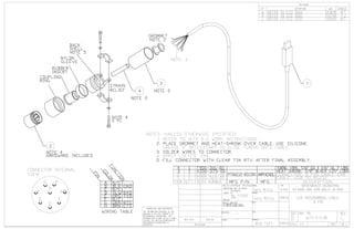
SlideShare a Scribd company logo
1 of 26
Download to read offline
TURRET (RoHS)
TERMINAL CONTACT: MACHINED C36000 BRASS 1/2 HARD
TERMINAL PLATING: SOFT NICKEL THEN SILVER
DIMENSIONS APPLY AFTER PLATING
PRODUCTION BODY: BLACK NYLON 6/6 PER ASTM D4066
PRODUCTION BODY MOLDED OVER CONTACT
PROTOTYPE BODY: SOMOS NEXT STEREOLITHOGRAPHY RESIN
THE INFORMATION CONTAINED IN THIS
DRAWING IS THE SOLE PROPERTY OF
ROTHENBUHLER ENGINEERING. ANY
REPRODUCTION IN PART OR AS A WHOLE
WITHOUT THE WRITTEN PERMISSION OF
ROTHENBUHLER ENGINEERING IS
PROHIBITED.
NEXT ASSY USED ON
APPLICATION
DIMENSIONS ARE IN INCHES
TOLERANCES:
LINEAR- X.X =
X.XX =
X.XXX =
ANGULAR- =
MATERIAL
FINISH
--
--
DRAWN
CHECKED
MECH.
ELEC.
APPROVED
DATE
SIZE DWG. NO. REV
SHEET 1 OF 1SCALE: 4:1
REVISIONS
DESCRIPTION DATE APPROVEDLTR
UNLESS OTHERWISE SPECIFIED:
524 RHODES ROAD, SEDRO WOOLLEY, WA 98284
BREAK ALL SHARP EDGES
ALL DIMENSIONS TO USAS Y14.5'66
125 FINISH ALL MACHINED SURFACES
JACK, CUSTOM BANANA, BLACK
1674-22-20-2-B5B
10/7/2013Tom Jacobson
±0.010
A REMOVED DRAIN SLOTS - NO ECO
J300-167-40
CHANGED CONTACT LOCK-IN FEATURE - NO ECOB
5/16-32 UNEF-2A
A
A 0
0.031
0.132
0.215
0.234
0.260
0.313
0.857
100.000°
ø 0.203
ø 0.161
0.010
ø 0.142
ø 0.122
0.031
0.031 0.181
0.313
0.857
0.969
ø 0.435
ø 0.098
ø 0.125
ø 0.161
ø 0.203
ø 0.225
R0.025 R0.025
0.719
SECTION A-A
9/23/14 RTREFER ECO 3706C
9/23/14 RT
9/23/14 RT
Gary McCoy 9/23/14
9/23/14Rich Taft
Technical Service Number: TSB-0016
Bulletin (TSB) Page: 1 of 5
TITLE: 1064-2-1 & 1072-3-2-1 RECEIVER “L7” INDUCTOR REPLACEMENT
Rothenbuhler
Engineering
Rothenbuhler Engineering Proprietary Notice
This document contains information which is the exclusive property of
Rothenbuhler Engineering. Distribution, reproduction, or use by others is
not permitted without the express written consent of Rothenbuhler
Engineering.
Signature Date
Author Gary McCoy 4/23/15
Approved Rich Taft 4/23/15
Document #: TSB0016
File Name: TSB0016 1064-2-1, 1072-3-2-1 Receiver PCBA’s.doc
Technical Service Number: TSB-0016
Bulletin (TSB) Page: 2 of 5
TITLE: 1064-2-1 & 1072-3-2-1 RECEIVER “L7” INDUCTOR REPLACEMENT
Table of Contents
Table of Contents..............................................................................................................................2
Table of Figures ................................................................................................................................2
Replacement of Toko Inductor L7 .....................................................................................................3
Objective of Change..........................................................................................................................3
Background .......................................................................................................................................3
Required Parts ..................................................................................................................................4
Required Items..................................................................................................................................4
1064-2-3 Installation..........................................................................................................................4
Table of Figures
Figure 1 1064-2-3 PCB, Inductor, Adapter, Assembly View ............................................................4
Figure 2 1064-2-3 PCB, Inductor, Adapter, Assembly Installed............................................................5
Technical Service Number: TSB-0016
Bulletin (TSB) Page: 3 of 5
TITLE: 1064-2-1 & 1072-3-2-1 RECEIVER “L7” INDUCTOR REPLACEMENT
Replacement of Toko Inductor L7
Objective of Change
The objective of this change is to replace obsolete through hole Toko Inductor p/n 5PNR-T1021Z
placed as designator L7 with an adapter PCB designed to accommodate a replacement surface
mount Toko Inductor p/n 614AN-9561Z.
Background
When a suitable replacement for original L7 Toko Inductor was found the mounting style changed
from through hole to surface mount with a value change from 680uH to 560uH. This change resulted
in necessary modifications to place L7 on current and existing 1064-2-1 and 1072-3-2-1 PCBA’s. New
Toko Inductor concurrently.
To correct this issue the 1064-2-3 PCB, Inductor, Adapter, Assembly was created as a drop-in
replacement to fit existing Inductor L7 mounting location while necessitating the change in value for
capacitor C21 from 180pH to 220pH on all 1064-2-1 and 1072-3-2-1 Receiver PCBA’s. The 1064-2-3
PCB, Inductor, Adapter will ultimately extend the maintenance life of existing units.
Technical Service Number: TSB-0016
Bulletin (TSB) Page: 4 of 5
TITLE: 1064-2-1 & 1072-3-2-1 RECEIVER “L7” INDUCTOR REPLACEMENT
Warning: The circuit board assemblies of the Receiver are susceptible to damage from Electro
Static Discharge (ESD). Observe proper ESD procedures while performing this update.
Warning: Ensure power is disconnected form the Receiver while performing the upgrade.
Required Parts
(1) 1064-2-3 PCB, Inductor, Adapter, Assembly (1) (C110-220-00) Capacitor, 220pf NPO, SMD
(1.5”) #24AWG, Buss-wire
Required Items
• Soldering equipment w/ Rosin Core Solder • Clear 732 RTV Sealant.
1064-2-3 Installation
1. After the 1064-2-1 or 1072-3-2-1 Receiver PCBA has been removed from the unit following
cautions and warning outlined above perform the following procedure to install the 1064-2-3
PCB, Inductor, Adapter, Assembly.
2. De-solder “L7” 680µH Inductor on the 1064-2-1-1 any Revision PCB and discard.
3. De-solder “C21” Capacitor, 180pf and discard.
4. Ensure solder is removed from all through holes of “L7” and then hand clean PCB using MEK
where work has been done
5. Solder new “C21” Capacitor, 220pf in place.
6. Apply small dab of clear RTV 732 sealant to bottom side of 1064-2-3 under “L1” installed
inductor prior to soldering buss wire keeping “J1” and “L7” mounting holes free of RTV.
7. Align “J1” of 1064-2-3 assembly over L7 as shown pressing firmly to set the RTV.
8. Feed #24AWG buss-wire through mounting holes “J1” and “L7” and solder buss-wire in place, then cut
buss-wire and repeat for each of (7) mounting holes. Ensure buss-wire is soldered (7places) on top of
1064-2-3 PCBA and bottom side of 1064-2-1-1 PCB.
Figure 1 1064-2-3 PCB, Inductor, Adapter, Assembly View
SOLDER #24 Buss-wires
BOTH SIDES
1064-2-3 PCB, Inductor,
Adapter, Assembly
Clear 732 RTV SEALANT
L1
J1
L7
1064-1-1-1 PCB
All Revisions
Technical Service Number: TSB-0016
Bulletin (TSB) Page: 5 of 5
TITLE: 1064-2-1 & 1072-3-2-1 RECEIVER “L7” INDUCTOR REPLACEMENT
9. Hand clean all solder joints and mask inductor L7 before using a brush to apply Humiseal
1B73 Conformal Coating to all rework areas.
Figure 2 1064-2-3 PCB, Inductor, Adapter, Assembly Installed
L7
Technical Service Number: TSB-0012
Bulletin (TSB) Page: 1 of 5
TITLE: 1072 RECIEVER
Rothenbuhler
Engineering
Rothenbuhler Engineering Proprietary Notice
This document contains information which is the exclusive property of
Rothenbuhler Engineering. Distribution, reproduction, or use by others is
not permitted without the express written consent of Rothenbuhler
Engineering.
Signature Date
Author Gary McCoy – Signature on File 2/13/14
Approved Rich Taft – Signature on File 2/13/14
Document #: TSB0012 Rev A
File Name: TSB0012 REV A – 1072
Interconnect Board.PDF
Technical Service Number: TSB-0012
Bulletin (TSB) Page: 2 of 5
TITLE: 1072 RECIEVER
REVISION HISTORY SHEET
ISSUE DATE REASON FOR CHANGE
REVISED BY PAST ISSUE
STATUS
A 2/13/14 Remove the Venting “NIB” from K1 (R050-
083-00) and K2 (R050-085-00) after all
spraying and/or washing is complete for all
new and existing 1072 Receivers.
GM C
PAST ISSUE STATUS: C = CURRENT; O = OBSOLETE
Technical Service Number: TSB-0012
Bulletin (TSB) Page: 3 of 5
TITLE: 1072 RECIEVER
Table of Contents
Revision History Sheet..........................................................................................................................2
Table of Contents..................................................................................................................................3
Table of Drawings .................................................................................................................................3
Objective of Change .............................................................................................................................4
Background...........................................................................................................................................4
Replacement Instruction ECO 3659......................................................................................................4
Rework Instructions from ECO 3659.....................................................................................................4
Table of Drawings
1072-3-4-B0 Rev K Assembly ..............................................................................................................5
Technical Service Number: TSB-0012
Bulletin (TSB) Page: 4 of 5
TITLE: 1072 RECIEVER
Rothenbuhler Engineering Service Center Information Packet
1072 Receiver
Objective of Change
The objective of this change is to improve the performance and longevity of the 1072 Whistle
Receiver relays on all new and existing 1072 Receivers.
Background
Relay K1 has had ongoing issues with sticking contacts in the field. The relay manufacturer
recommends that the venting “NIB” be removed to allow pressure relief and maximize electrical
longevity. Relay K2 should also be vented.
Replacement Instruction ECO 3659
1) 1072-3-4 Interconnect Board Assembly
a. If replacing components K1 Relay, 5v, SPDT, 20A (T90S5D12-5) (R050-
083-00) and/or K2 Relay, 12 VDC, mini (RoHS) (R050-085-00) remove and
install new components.
b. After installation it is necessary to clean and spray work area with
humiseal, making sure components are masked properly as described in
notes on the 1072-3-4-B0 Rev K Assembly Figure 1 drawing.
c. After cleaning and spraying has been performed remove venting “NIB” with
a sharp knife. Refer to 1072-3-4-B0 Rev K Assembly Figure 1 for “NIB”
location.
Rework Instruction from ECO 3659
1) 1072-3-4 Interconnect Board Assembly
a. Remove venting “NIB” with a sharp knife on K1 Relay, 5v, SPDT, 20A
(T90S5D12-5) (R050-083-00) and/or K2 Relay, 12 VDC, mini (RoHS)
(R050-085-00) as units come in for repair or for routine service. Venting
“NIB” is shown on 1072-3-4-B0 Rev K Assembly Figure 1 as a reference
when removing.
Technical Service Number: TSB-0012
Bulletin (TSB) Page: 5 of 5
TITLE: 1072 RECIEVER
1072-3-4-B0 Rev K Assembly Figure 1
Number: AMP-126
Manufacturing Process Revision: C
Specification (AMP) Page: 1 of 6
TITLE: 1063-1-3 SWITCH ASSEMBLY
NAME FUNCTION SIGNATURE DATE
PREPARED BY: Gary McCoy Document Control Signature on File 6-18-15
AUTHORIZED BY: Rich Taft Engineering Manager Signature on File 6-24-15
Deborah Gregory Production Coordinator Signature on File 6-18-15
Steve Winters
Operations Manager
Quality Manager
Signature on File 6-24-15
Glenda Ransberger Production Supervisor Signature on File 6-18-15
Rothenbuhler Engineering Proprietary Notice
This document contains information which is the exclusive property of Rothenbuhler
Engineering. Distribution, reproduction, or use by others is not permitted without the
express written consent of Rothenbuhler Engineering.
Number: AMP-126
Manufacturing Process Revision: C
Specification (AMP) Page: 2 of 6
TITLE: 1063-1-3 SWITCH ASSEMBLY
REVISION HISTORY SHEET
ISSUE DATE REASON FOR CHANGE
REVISED
BY
PAST
ISSUE
STATUS
A 07/12/07 Initial Release NA O
B 6/8/09 Update instructions to clarify that the
cork washer is used. Included lock
washer is not used.
LLN O
C 6/26/15 Changed # of ties in assembly from 4 to
2. Specified orientation of wire routing
for use in the 1100 assemblies. Updated
Switch Illustration 1-1.
GMM C
PAST ISSUE STATUS: C = CURRENT; O = OBSOLETE
Number: AMP-126
Manufacturing Process Revision: C
Specification (AMP) Page: 3 of 6
TITLE: 1063-1-3 SWITCH ASSEMBLY
1. PURPOSE
1.1.This work procedure is for the preparation and assembly of the switch.
2. SCOPE
2.1.This work instruction procedure covers the tools required, drawings to be
referenced, and instructions to be followed in the factory’s preparation and
assembly of the switch.
3. RESPONSIBILITY
3.1.The Assembly Supervisor will update this work instruction as required.
3.2.The Production Supervisor, Quality Manager, Engineering Manager, and
Operations Manager will approve any changes to this instruction by signing
the cover sheet.
3.3.Document Control will maintain this instruction on the Quality drive such that
only the most current version is available to all relevant workers.
3.4.The Production workers will reference this work instruction when preparing
and assembling the sub-components of the switch.
4. DEFINITION
4.1.None
5. REFERENCES
5.1. Part Number: 1063-1-3
5.2. Description: Switch Assembly
5.3. Drawing Number: 1063-1-3-AO Revision: current revision
Number: AMP-126
Manufacturing Process Revision: C
Specification (AMP) Page: 4 of 6
TITLE: 1063-1-3 SWITCH ASSEMBLY
6. PROCEDURE
6.1.Special Tools and Supplies Required: (All tools should be calibrated as
required per the calibration schedule)
6.1.1. needle nose pliers
6.1.2. dikes (diagonal cutters)
6.1.3. ruler
6.1.4. crimping tool # 90289-1
6.1.5. rosin core wire solder
6.1.6. solder iron
6.1.7. switch wiring jig
6.1.8. Paladin wire strippers (or equivalent)
6.2 Work Instructions (Per approved drawings, assemble sub-components as
follows):
6.2.1 Cut 24 AWG wires to 7 ¼” lengths. WIRE LENGTH IS CRITICAL.
6.2.2 Strip wire insulation 1/8” on one end.
6.2.3 Use the 90289-1 crimping tool to attach a connector pin to each of the
stripped ends. Have crimped pins inspected.
6.2.4 Insert the connector pins into housing as shown on drawing.
6.2.5 Strip the insulation on opposite end of wires ¼” and tin.
6.2.6 Cut 20 AWG buss wire to 2” lengths.
6.2.7 Place (2) switches into the switch wiring jig as oriented on drawing
(terminal 2 is away from you, terminal 1 is towards you, terminal 3 is to
the left, and terminal 4 is to the right).
6.2.8 Solder the 20 AWG buss wire between terminal 4 of left switch and
terminal 3 of right switch as shown on drawing. The wire shall run
through the hole in the terminal and be wrapped to contact both sides
of the terminal. Solder the buss wire to the switches so that the wire
has an “S” in it for stress relief. Do not completely fill the pin 3 hole
with solder as you will need to solder the brown wire to this same pin.
Number: AMP-126
Manufacturing Process Revision: C
Specification (AMP) Page: 5 of 6
TITLE: 1063-1-3 SWITCH ASSEMBLY
6.2.9 Solder the 24 AWG wires to the appropriate terminals. These wires
need to be attached in the same manner; the wire shall run through the
hole in the terminal and be wrapped to contact both sides of the
terminal.
Red = pin 3 of left switch
Brown = pin 3 of right switch
Orange = pin 4 of right switch
6.2.10 Attach (2) cable ties to switch assembly as shown in illustration below.
Illustration 1-1
Number: AMP-126
Manufacturing Process Revision: C
Specification (AMP) Page: 6 of 6
TITLE: 1063-1-3 SWITCH ASSEMBLY
6.2.11 Install the cork washer and a nut on each switch (hardware included; if
lock washer is included it can be disposed of).
6.2.12 Deliver completed switch assemblies to inspection. Inspector will
inspect and test switches then return them for conformal coating
process.
6.2.13 Using cardboard switch holder jig located in cabinet; insert switches
into holes wire side up and keep all the switch assemblies aligned in
the same direction.
6.2.14 Place switches in conformal coating booth, push-button of switch
facing down. Spray only the back side of switches with Humiseal
1B73 Conformal coating. Do not spray connector housing or push-
button side of switch.
7. Attachments
7.1. None
Drawing samples 1063, 1670, 1673, 1674 SolidWorks ACAD

More Related Content

What's hot

Electrical standard symbols
Electrical standard symbolsElectrical standard symbols
Electrical standard symbolsasifsalafy
 
スパイス・パークの全リスト(2013年5月度)
スパイス・パークの全リスト(2013年5月度)スパイス・パークの全リスト(2013年5月度)
スパイス・パークの全リスト(2013年5月度)spicepark
 
2012年7月度アップデートのスパイスモデルリスト
2012年7月度アップデートのスパイスモデルリスト2012年7月度アップデートのスパイスモデルリスト
2012年7月度アップデートのスパイスモデルリストTsuyoshi Horigome
 
5-Terminal Components
5-Terminal Components5-Terminal Components
5-Terminal ComponentsLinn Liu
 
Anambra 2 pictorial presentation of some projects
Anambra 2 pictorial presentation of some projectsAnambra 2 pictorial presentation of some projects
Anambra 2 pictorial presentation of some projectsOSSAP-MDGS
 

What's hot (15)

Symbols.pdf
Symbols.pdfSymbols.pdf
Symbols.pdf
 
Electrical standard symbols
Electrical standard symbolsElectrical standard symbols
Electrical standard symbols
 
1 ca1s
1 ca1s1 ca1s
1 ca1s
 
Control valve
Control valveControl valve
Control valve
 
Brix laptop cedar intel mb (1)
Brix laptop cedar intel mb (1)Brix laptop cedar intel mb (1)
Brix laptop cedar intel mb (1)
 
Fabrication Drawings
Fabrication DrawingsFabrication Drawings
Fabrication Drawings
 
Filarc.PDF
Filarc.PDFFilarc.PDF
Filarc.PDF
 
スパイス・パークの全リスト(2013年5月度)
スパイス・パークの全リスト(2013年5月度)スパイス・パークの全リスト(2013年5月度)
スパイス・パークの全リスト(2013年5月度)
 
2012年7月度アップデートのスパイスモデルリスト
2012年7月度アップデートのスパイスモデルリスト2012年7月度アップデートのスパイスモデルリスト
2012年7月度アップデートのスパイスモデルリスト
 
5-Terminal Components
5-Terminal Components5-Terminal Components
5-Terminal Components
 
5988 5846 en+an-1285+24aug10%2c0
5988 5846 en+an-1285+24aug10%2c05988 5846 en+an-1285+24aug10%2c0
5988 5846 en+an-1285+24aug10%2c0
 
1052-1-GA01_A
1052-1-GA01_A1052-1-GA01_A
1052-1-GA01_A
 
1258 onf bfv
1258   onf bfv1258   onf bfv
1258 onf bfv
 
Butterfly valve
Butterfly valveButterfly valve
Butterfly valve
 
Anambra 2 pictorial presentation of some projects
Anambra 2 pictorial presentation of some projectsAnambra 2 pictorial presentation of some projects
Anambra 2 pictorial presentation of some projects
 

Similar to Drawing samples 1063, 1670, 1673, 1674 SolidWorks ACAD

Current Transformer Drawing and GTP for MSETCL
Current Transformer Drawing and GTP for MSETCLCurrent Transformer Drawing and GTP for MSETCL
Current Transformer Drawing and GTP for MSETCLDeelipZope
 
スパイス・パークのアップデートリスト(2013年10月度)
スパイス・パークのアップデートリスト(2013年10月度)スパイス・パークのアップデートリスト(2013年10月度)
スパイス・パークのアップデートリスト(2013年10月度)Tsuyoshi Horigome
 
Kraus & naimer control switches for special application kn130 gb0816
Kraus & naimer control switches for special application kn130 gb0816Kraus & naimer control switches for special application kn130 gb0816
Kraus & naimer control switches for special application kn130 gb0816Dien Ha The
 
Lcl users manual electrical drawings
Lcl users manual electrical drawingsLcl users manual electrical drawings
Lcl users manual electrical drawingsbibimisael
 
HAKKO_936_Schematic_Rendered_by_Tom_Hamm.pdf
HAKKO_936_Schematic_Rendered_by_Tom_Hamm.pdfHAKKO_936_Schematic_Rendered_by_Tom_Hamm.pdf
HAKKO_936_Schematic_Rendered_by_Tom_Hamm.pdfEnjangSupriatna1
 
スパイス・パークのアップデートリスト(2013年8月度)
スパイス・パークのアップデートリスト(2013年8月度)スパイス・パークのアップデートリスト(2013年8月度)
スパイス・パークのアップデートリスト(2013年8月度)spicepark
 
スパイス・パークのアップデートリスト(2013年7月度)
スパイス・パークのアップデートリスト(2013年7月度)スパイス・パークのアップデートリスト(2013年7月度)
スパイス・パークのアップデートリスト(2013年7月度)spicepark
 
LDavis_work_examples
LDavis_work_examplesLDavis_work_examples
LDavis_work_examplesLoren Davis
 
Orientation Frame Assembly
Orientation Frame AssemblyOrientation Frame Assembly
Orientation Frame AssemblyEarl Schneider
 
02 QUALITY CONTROL TEST REPORTS FORMATS
02 QUALITY CONTROL TEST REPORTS FORMATS02 QUALITY CONTROL TEST REPORTS FORMATS
02 QUALITY CONTROL TEST REPORTS FORMATSMary Calkins
 
BN-DS-E2_02.pdf
BN-DS-E2_02.pdfBN-DS-E2_02.pdf
BN-DS-E2_02.pdfRonan61
 
PLF-1408-AT-SD-CO-213 - REV 00
PLF-1408-AT-SD-CO-213 - REV 00PLF-1408-AT-SD-CO-213 - REV 00
PLF-1408-AT-SD-CO-213 - REV 00Mansoor Sakharkar
 
Iec electric-symbols-bn-ds-e2 02
Iec electric-symbols-bn-ds-e2 02Iec electric-symbols-bn-ds-e2 02
Iec electric-symbols-bn-ds-e2 02Tôi Chết
 
Water Source HP Loop_Controls
Water Source HP Loop_ControlsWater Source HP Loop_Controls
Water Source HP Loop_ControlsElenzer Datu
 
Example residential project
Example residential projectExample residential project
Example residential projectSolarDesigns
 

Similar to Drawing samples 1063, 1670, 1673, 1674 SolidWorks ACAD (20)

ProcContSite
ProcContSiteProcContSite
ProcContSite
 
Current Transformer Drawing and GTP for MSETCL
Current Transformer Drawing and GTP for MSETCLCurrent Transformer Drawing and GTP for MSETCL
Current Transformer Drawing and GTP for MSETCL
 
スパイス・パークのアップデートリスト(2013年10月度)
スパイス・パークのアップデートリスト(2013年10月度)スパイス・パークのアップデートリスト(2013年10月度)
スパイス・パークのアップデートリスト(2013年10月度)
 
Kraus & naimer control switches for special application kn130 gb0816
Kraus & naimer control switches for special application kn130 gb0816Kraus & naimer control switches for special application kn130 gb0816
Kraus & naimer control switches for special application kn130 gb0816
 
Sch 28303 b
Sch 28303 bSch 28303 b
Sch 28303 b
 
Lcl users manual electrical drawings
Lcl users manual electrical drawingsLcl users manual electrical drawings
Lcl users manual electrical drawings
 
HAKKO_936_Schematic_Rendered_by_Tom_Hamm.pdf
HAKKO_936_Schematic_Rendered_by_Tom_Hamm.pdfHAKKO_936_Schematic_Rendered_by_Tom_Hamm.pdf
HAKKO_936_Schematic_Rendered_by_Tom_Hamm.pdf
 
スパイス・パークのアップデートリスト(2013年8月度)
スパイス・パークのアップデートリスト(2013年8月度)スパイス・パークのアップデートリスト(2013年8月度)
スパイス・パークのアップデートリスト(2013年8月度)
 
dc2026c1-sch.pdf
dc2026c1-sch.pdfdc2026c1-sch.pdf
dc2026c1-sch.pdf
 
スパイス・パークのアップデートリスト(2013年7月度)
スパイス・パークのアップデートリスト(2013年7月度)スパイス・パークのアップデートリスト(2013年7月度)
スパイス・パークのアップデートリスト(2013年7月度)
 
LDavis_work_examples
LDavis_work_examplesLDavis_work_examples
LDavis_work_examples
 
Orientation Frame Assembly
Orientation Frame AssemblyOrientation Frame Assembly
Orientation Frame Assembly
 
02 QUALITY CONTROL TEST REPORTS FORMATS
02 QUALITY CONTROL TEST REPORTS FORMATS02 QUALITY CONTROL TEST REPORTS FORMATS
02 QUALITY CONTROL TEST REPORTS FORMATS
 
BN-DS-E2_02.pdf
BN-DS-E2_02.pdfBN-DS-E2_02.pdf
BN-DS-E2_02.pdf
 
delixicat.pdf
delixicat.pdfdelixicat.pdf
delixicat.pdf
 
PLF-1408-AT-SD-CO-213 - REV 00
PLF-1408-AT-SD-CO-213 - REV 00PLF-1408-AT-SD-CO-213 - REV 00
PLF-1408-AT-SD-CO-213 - REV 00
 
Iec electric-symbols-bn-ds-e2 02
Iec electric-symbols-bn-ds-e2 02Iec electric-symbols-bn-ds-e2 02
Iec electric-symbols-bn-ds-e2 02
 
Water Source HP Loop_Controls
Water Source HP Loop_ControlsWater Source HP Loop_Controls
Water Source HP Loop_Controls
 
E3.pdf
E3.pdfE3.pdf
E3.pdf
 
Example residential project
Example residential projectExample residential project
Example residential project
 

Drawing samples 1063, 1670, 1673, 1674 SolidWorks ACAD

  • 1.
  • 2.
  • 3.
  • 4.
  • 5. TURRET (RoHS) TERMINAL CONTACT: MACHINED C36000 BRASS 1/2 HARD TERMINAL PLATING: SOFT NICKEL THEN SILVER DIMENSIONS APPLY AFTER PLATING PRODUCTION BODY: BLACK NYLON 6/6 PER ASTM D4066 PRODUCTION BODY MOLDED OVER CONTACT PROTOTYPE BODY: SOMOS NEXT STEREOLITHOGRAPHY RESIN THE INFORMATION CONTAINED IN THIS DRAWING IS THE SOLE PROPERTY OF ROTHENBUHLER ENGINEERING. ANY REPRODUCTION IN PART OR AS A WHOLE WITHOUT THE WRITTEN PERMISSION OF ROTHENBUHLER ENGINEERING IS PROHIBITED. NEXT ASSY USED ON APPLICATION DIMENSIONS ARE IN INCHES TOLERANCES: LINEAR- X.X = X.XX = X.XXX = ANGULAR- = MATERIAL FINISH -- -- DRAWN CHECKED MECH. ELEC. APPROVED DATE SIZE DWG. NO. REV SHEET 1 OF 1SCALE: 4:1 REVISIONS DESCRIPTION DATE APPROVEDLTR UNLESS OTHERWISE SPECIFIED: 524 RHODES ROAD, SEDRO WOOLLEY, WA 98284 BREAK ALL SHARP EDGES ALL DIMENSIONS TO USAS Y14.5'66 125 FINISH ALL MACHINED SURFACES JACK, CUSTOM BANANA, BLACK 1674-22-20-2-B5B 10/7/2013Tom Jacobson ±0.010 A REMOVED DRAIN SLOTS - NO ECO J300-167-40 CHANGED CONTACT LOCK-IN FEATURE - NO ECOB 5/16-32 UNEF-2A A A 0 0.031 0.132 0.215 0.234 0.260 0.313 0.857 100.000° ø 0.203 ø 0.161 0.010 ø 0.142 ø 0.122 0.031 0.031 0.181 0.313 0.857 0.969 ø 0.435 ø 0.098 ø 0.125 ø 0.161 ø 0.203 ø 0.225 R0.025 R0.025 0.719 SECTION A-A 9/23/14 RTREFER ECO 3706C 9/23/14 RT 9/23/14 RT Gary McCoy 9/23/14 9/23/14Rich Taft
  • 6. Technical Service Number: TSB-0016 Bulletin (TSB) Page: 1 of 5 TITLE: 1064-2-1 & 1072-3-2-1 RECEIVER “L7” INDUCTOR REPLACEMENT Rothenbuhler Engineering Rothenbuhler Engineering Proprietary Notice This document contains information which is the exclusive property of Rothenbuhler Engineering. Distribution, reproduction, or use by others is not permitted without the express written consent of Rothenbuhler Engineering. Signature Date Author Gary McCoy 4/23/15 Approved Rich Taft 4/23/15 Document #: TSB0016 File Name: TSB0016 1064-2-1, 1072-3-2-1 Receiver PCBA’s.doc
  • 7. Technical Service Number: TSB-0016 Bulletin (TSB) Page: 2 of 5 TITLE: 1064-2-1 & 1072-3-2-1 RECEIVER “L7” INDUCTOR REPLACEMENT Table of Contents Table of Contents..............................................................................................................................2 Table of Figures ................................................................................................................................2 Replacement of Toko Inductor L7 .....................................................................................................3 Objective of Change..........................................................................................................................3 Background .......................................................................................................................................3 Required Parts ..................................................................................................................................4 Required Items..................................................................................................................................4 1064-2-3 Installation..........................................................................................................................4 Table of Figures Figure 1 1064-2-3 PCB, Inductor, Adapter, Assembly View ............................................................4 Figure 2 1064-2-3 PCB, Inductor, Adapter, Assembly Installed............................................................5
  • 8. Technical Service Number: TSB-0016 Bulletin (TSB) Page: 3 of 5 TITLE: 1064-2-1 & 1072-3-2-1 RECEIVER “L7” INDUCTOR REPLACEMENT Replacement of Toko Inductor L7 Objective of Change The objective of this change is to replace obsolete through hole Toko Inductor p/n 5PNR-T1021Z placed as designator L7 with an adapter PCB designed to accommodate a replacement surface mount Toko Inductor p/n 614AN-9561Z. Background When a suitable replacement for original L7 Toko Inductor was found the mounting style changed from through hole to surface mount with a value change from 680uH to 560uH. This change resulted in necessary modifications to place L7 on current and existing 1064-2-1 and 1072-3-2-1 PCBA’s. New Toko Inductor concurrently. To correct this issue the 1064-2-3 PCB, Inductor, Adapter, Assembly was created as a drop-in replacement to fit existing Inductor L7 mounting location while necessitating the change in value for capacitor C21 from 180pH to 220pH on all 1064-2-1 and 1072-3-2-1 Receiver PCBA’s. The 1064-2-3 PCB, Inductor, Adapter will ultimately extend the maintenance life of existing units.
  • 9. Technical Service Number: TSB-0016 Bulletin (TSB) Page: 4 of 5 TITLE: 1064-2-1 & 1072-3-2-1 RECEIVER “L7” INDUCTOR REPLACEMENT Warning: The circuit board assemblies of the Receiver are susceptible to damage from Electro Static Discharge (ESD). Observe proper ESD procedures while performing this update. Warning: Ensure power is disconnected form the Receiver while performing the upgrade. Required Parts (1) 1064-2-3 PCB, Inductor, Adapter, Assembly (1) (C110-220-00) Capacitor, 220pf NPO, SMD (1.5”) #24AWG, Buss-wire Required Items • Soldering equipment w/ Rosin Core Solder • Clear 732 RTV Sealant. 1064-2-3 Installation 1. After the 1064-2-1 or 1072-3-2-1 Receiver PCBA has been removed from the unit following cautions and warning outlined above perform the following procedure to install the 1064-2-3 PCB, Inductor, Adapter, Assembly. 2. De-solder “L7” 680µH Inductor on the 1064-2-1-1 any Revision PCB and discard. 3. De-solder “C21” Capacitor, 180pf and discard. 4. Ensure solder is removed from all through holes of “L7” and then hand clean PCB using MEK where work has been done 5. Solder new “C21” Capacitor, 220pf in place. 6. Apply small dab of clear RTV 732 sealant to bottom side of 1064-2-3 under “L1” installed inductor prior to soldering buss wire keeping “J1” and “L7” mounting holes free of RTV. 7. Align “J1” of 1064-2-3 assembly over L7 as shown pressing firmly to set the RTV. 8. Feed #24AWG buss-wire through mounting holes “J1” and “L7” and solder buss-wire in place, then cut buss-wire and repeat for each of (7) mounting holes. Ensure buss-wire is soldered (7places) on top of 1064-2-3 PCBA and bottom side of 1064-2-1-1 PCB. Figure 1 1064-2-3 PCB, Inductor, Adapter, Assembly View SOLDER #24 Buss-wires BOTH SIDES 1064-2-3 PCB, Inductor, Adapter, Assembly Clear 732 RTV SEALANT L1 J1 L7 1064-1-1-1 PCB All Revisions
  • 10. Technical Service Number: TSB-0016 Bulletin (TSB) Page: 5 of 5 TITLE: 1064-2-1 & 1072-3-2-1 RECEIVER “L7” INDUCTOR REPLACEMENT 9. Hand clean all solder joints and mask inductor L7 before using a brush to apply Humiseal 1B73 Conformal Coating to all rework areas. Figure 2 1064-2-3 PCB, Inductor, Adapter, Assembly Installed L7
  • 11. Technical Service Number: TSB-0012 Bulletin (TSB) Page: 1 of 5 TITLE: 1072 RECIEVER Rothenbuhler Engineering Rothenbuhler Engineering Proprietary Notice This document contains information which is the exclusive property of Rothenbuhler Engineering. Distribution, reproduction, or use by others is not permitted without the express written consent of Rothenbuhler Engineering. Signature Date Author Gary McCoy – Signature on File 2/13/14 Approved Rich Taft – Signature on File 2/13/14 Document #: TSB0012 Rev A File Name: TSB0012 REV A – 1072 Interconnect Board.PDF
  • 12. Technical Service Number: TSB-0012 Bulletin (TSB) Page: 2 of 5 TITLE: 1072 RECIEVER REVISION HISTORY SHEET ISSUE DATE REASON FOR CHANGE REVISED BY PAST ISSUE STATUS A 2/13/14 Remove the Venting “NIB” from K1 (R050- 083-00) and K2 (R050-085-00) after all spraying and/or washing is complete for all new and existing 1072 Receivers. GM C PAST ISSUE STATUS: C = CURRENT; O = OBSOLETE
  • 13. Technical Service Number: TSB-0012 Bulletin (TSB) Page: 3 of 5 TITLE: 1072 RECIEVER Table of Contents Revision History Sheet..........................................................................................................................2 Table of Contents..................................................................................................................................3 Table of Drawings .................................................................................................................................3 Objective of Change .............................................................................................................................4 Background...........................................................................................................................................4 Replacement Instruction ECO 3659......................................................................................................4 Rework Instructions from ECO 3659.....................................................................................................4 Table of Drawings 1072-3-4-B0 Rev K Assembly ..............................................................................................................5
  • 14. Technical Service Number: TSB-0012 Bulletin (TSB) Page: 4 of 5 TITLE: 1072 RECIEVER Rothenbuhler Engineering Service Center Information Packet 1072 Receiver Objective of Change The objective of this change is to improve the performance and longevity of the 1072 Whistle Receiver relays on all new and existing 1072 Receivers. Background Relay K1 has had ongoing issues with sticking contacts in the field. The relay manufacturer recommends that the venting “NIB” be removed to allow pressure relief and maximize electrical longevity. Relay K2 should also be vented. Replacement Instruction ECO 3659 1) 1072-3-4 Interconnect Board Assembly a. If replacing components K1 Relay, 5v, SPDT, 20A (T90S5D12-5) (R050- 083-00) and/or K2 Relay, 12 VDC, mini (RoHS) (R050-085-00) remove and install new components. b. After installation it is necessary to clean and spray work area with humiseal, making sure components are masked properly as described in notes on the 1072-3-4-B0 Rev K Assembly Figure 1 drawing. c. After cleaning and spraying has been performed remove venting “NIB” with a sharp knife. Refer to 1072-3-4-B0 Rev K Assembly Figure 1 for “NIB” location. Rework Instruction from ECO 3659 1) 1072-3-4 Interconnect Board Assembly a. Remove venting “NIB” with a sharp knife on K1 Relay, 5v, SPDT, 20A (T90S5D12-5) (R050-083-00) and/or K2 Relay, 12 VDC, mini (RoHS) (R050-085-00) as units come in for repair or for routine service. Venting “NIB” is shown on 1072-3-4-B0 Rev K Assembly Figure 1 as a reference when removing.
  • 15. Technical Service Number: TSB-0012 Bulletin (TSB) Page: 5 of 5 TITLE: 1072 RECIEVER 1072-3-4-B0 Rev K Assembly Figure 1
  • 16. Number: AMP-126 Manufacturing Process Revision: C Specification (AMP) Page: 1 of 6 TITLE: 1063-1-3 SWITCH ASSEMBLY NAME FUNCTION SIGNATURE DATE PREPARED BY: Gary McCoy Document Control Signature on File 6-18-15 AUTHORIZED BY: Rich Taft Engineering Manager Signature on File 6-24-15 Deborah Gregory Production Coordinator Signature on File 6-18-15 Steve Winters Operations Manager Quality Manager Signature on File 6-24-15 Glenda Ransberger Production Supervisor Signature on File 6-18-15 Rothenbuhler Engineering Proprietary Notice This document contains information which is the exclusive property of Rothenbuhler Engineering. Distribution, reproduction, or use by others is not permitted without the express written consent of Rothenbuhler Engineering.
  • 17. Number: AMP-126 Manufacturing Process Revision: C Specification (AMP) Page: 2 of 6 TITLE: 1063-1-3 SWITCH ASSEMBLY REVISION HISTORY SHEET ISSUE DATE REASON FOR CHANGE REVISED BY PAST ISSUE STATUS A 07/12/07 Initial Release NA O B 6/8/09 Update instructions to clarify that the cork washer is used. Included lock washer is not used. LLN O C 6/26/15 Changed # of ties in assembly from 4 to 2. Specified orientation of wire routing for use in the 1100 assemblies. Updated Switch Illustration 1-1. GMM C PAST ISSUE STATUS: C = CURRENT; O = OBSOLETE
  • 18. Number: AMP-126 Manufacturing Process Revision: C Specification (AMP) Page: 3 of 6 TITLE: 1063-1-3 SWITCH ASSEMBLY 1. PURPOSE 1.1.This work procedure is for the preparation and assembly of the switch. 2. SCOPE 2.1.This work instruction procedure covers the tools required, drawings to be referenced, and instructions to be followed in the factory’s preparation and assembly of the switch. 3. RESPONSIBILITY 3.1.The Assembly Supervisor will update this work instruction as required. 3.2.The Production Supervisor, Quality Manager, Engineering Manager, and Operations Manager will approve any changes to this instruction by signing the cover sheet. 3.3.Document Control will maintain this instruction on the Quality drive such that only the most current version is available to all relevant workers. 3.4.The Production workers will reference this work instruction when preparing and assembling the sub-components of the switch. 4. DEFINITION 4.1.None 5. REFERENCES 5.1. Part Number: 1063-1-3 5.2. Description: Switch Assembly 5.3. Drawing Number: 1063-1-3-AO Revision: current revision
  • 19. Number: AMP-126 Manufacturing Process Revision: C Specification (AMP) Page: 4 of 6 TITLE: 1063-1-3 SWITCH ASSEMBLY 6. PROCEDURE 6.1.Special Tools and Supplies Required: (All tools should be calibrated as required per the calibration schedule) 6.1.1. needle nose pliers 6.1.2. dikes (diagonal cutters) 6.1.3. ruler 6.1.4. crimping tool # 90289-1 6.1.5. rosin core wire solder 6.1.6. solder iron 6.1.7. switch wiring jig 6.1.8. Paladin wire strippers (or equivalent) 6.2 Work Instructions (Per approved drawings, assemble sub-components as follows): 6.2.1 Cut 24 AWG wires to 7 ¼” lengths. WIRE LENGTH IS CRITICAL. 6.2.2 Strip wire insulation 1/8” on one end. 6.2.3 Use the 90289-1 crimping tool to attach a connector pin to each of the stripped ends. Have crimped pins inspected. 6.2.4 Insert the connector pins into housing as shown on drawing. 6.2.5 Strip the insulation on opposite end of wires ¼” and tin. 6.2.6 Cut 20 AWG buss wire to 2” lengths. 6.2.7 Place (2) switches into the switch wiring jig as oriented on drawing (terminal 2 is away from you, terminal 1 is towards you, terminal 3 is to the left, and terminal 4 is to the right). 6.2.8 Solder the 20 AWG buss wire between terminal 4 of left switch and terminal 3 of right switch as shown on drawing. The wire shall run through the hole in the terminal and be wrapped to contact both sides of the terminal. Solder the buss wire to the switches so that the wire has an “S” in it for stress relief. Do not completely fill the pin 3 hole with solder as you will need to solder the brown wire to this same pin.
  • 20. Number: AMP-126 Manufacturing Process Revision: C Specification (AMP) Page: 5 of 6 TITLE: 1063-1-3 SWITCH ASSEMBLY 6.2.9 Solder the 24 AWG wires to the appropriate terminals. These wires need to be attached in the same manner; the wire shall run through the hole in the terminal and be wrapped to contact both sides of the terminal. Red = pin 3 of left switch Brown = pin 3 of right switch Orange = pin 4 of right switch 6.2.10 Attach (2) cable ties to switch assembly as shown in illustration below. Illustration 1-1
  • 21. Number: AMP-126 Manufacturing Process Revision: C Specification (AMP) Page: 6 of 6 TITLE: 1063-1-3 SWITCH ASSEMBLY 6.2.11 Install the cork washer and a nut on each switch (hardware included; if lock washer is included it can be disposed of). 6.2.12 Deliver completed switch assemblies to inspection. Inspector will inspect and test switches then return them for conformal coating process. 6.2.13 Using cardboard switch holder jig located in cabinet; insert switches into holes wire side up and keep all the switch assemblies aligned in the same direction. 6.2.14 Place switches in conformal coating booth, push-button of switch facing down. Spray only the back side of switches with Humiseal 1B73 Conformal coating. Do not spray connector housing or push- button side of switch. 7. Attachments 7.1. None