Call Girls Service Nagpur Tanvi Call 7001035870 Meet With Nagpur Escorts
Method for ascertaining load capacity of cranes
1. |MITKUDOTORI RATHITAMAMLAMAUS 20170260029A1
(19)United States
(12)Patent Application Publication (10)Pub.No.:US2017/0260029 A1
Edeler et al. (43) Pub. Date: Sep. 14, 2017
(54) METHOD FOR ASCERTAINING THE LOAD
CAPACITY OF A CRANE AND CRANE
(52)(71) Applicant:Manitowoc Crane Group France
SAS, Dardilly Cedex (FR )
GOIM 99/00 (2006.01)
B66C 23/88 (2006.01)
U.S. CI.
CPC ......... .... B66C 13/16 (2013.01); B66C 23/88
(2013.01);G07C 5/085 (2013.01);G07C
5/0816 (2013.01);GOIM 99/005 (2013.01);
B66C 23/36 (2013.01)
(57) ABSTRACT
(72) Inventors: Christoph Edeler, Oldenburg (DE);
Frank Richter,Wilhelmshaven (DE);
Frank C. Schnittker,Wuerzburg (DE)
(21) Appl.No.:15/454,641
(22) Filed: Mar.9,2017
(30) Foreign Application Priority Data
Mar. 10,2016 (DE) ............ 102016104358.3. . . . . . . . .
A method for ascertaining the load capacity of a functional
element of a crane, the load capacity of a sub-assembly of
a craneor the load capacity of a crane,wherein: amaximum
bearing load is calculated for a specifically occurring con
figuration and/or specifically occurring state parameters
and/or specifically occurring operating parameters on the
basis of a predetermined formula ; and the calculation is
verified on the basis of stored bearing load values.
Publication Classification
Int. Ci.
B66C 13/16 (2006.01)
G07C 5/08 (2006.01)
(51)
angle,telescopic
state, tip , ...
configuring theboom
? 2D strength curve
boom curve,
counterweight..... configuringthe superstructure
? 2D strength curve
once(changeinconfiguration
superstructure
undercarriage
configuration
calculating a
slewing angle-dependent
3D bearing load volume
=> large gradients can be detected
pre-calculatedinputs/userinputs/controlelements/sensordata siewing angle bearing load forthe current angle
? 2D bearing loadcurve
cylinder pressure.
angie, force pro
y current load
joystick input.
wind sensor, etc.,
support pressure
firrit
continuouslysafety:
-> reduced speed and/or
shutdown
c.g.actual speed
drive controller
7. PatentApplication Publication Sep.14,2017 Sheet6 of6 US 2017/0260029 A1
angle,telescopicstate, tip,...
configuring the boom
2D strength curve
boom curve,
counterweight,... configuringthe superstructure
? 2D strength curve
once(changeinconfiguration
superstructure/
undercarriage
configuration
calculatinga
slewing angle-dependent
? 3D bearing load volume
? large gradients can be detected
LLLLLLLLLLLLLLLLLLLLLLLLLLL
pre-calculatedinputs/userinputs/controlelements/sensordata slewing angle bearing load for the currentangle
? 2D bearing load curve
cylinderpressure,
angle, force
? currentload
joystick input,
wind sensor,etc.,
support pressure
limit
continuouslysafety;
? reduced speed and/or
shutdown
e.g.actualspeedtuttttttttttttttttttt
drive controller
Figure 10
8. US 2017/0260029 A1 Sep. 14, 2017
METHOD FOR ASCERTAINING THE LOAD
CAPACITY OF A CRANE AND CRANE
[0001] The invention relates to a method for securely
ascertaining the load capacity of a crane and formonitoring
the safety of a crane, and to a cranewhich can perform said
method and can for example comprise a variable supporting
base. The invention also relates to calculating a three
dimensional work curve and ascertaining the permissible
speeds when functional elements of the crane aremoved.
[0002] The load capacity of a crane is composed of
multiple sub -assembly -specific individual load capacities or
the threshold exposures of various crane components or
crane sub-assemblies. Some threshold exposures can be
ascertained relatively easily on the basis of a few parameters
or are constant for a number of states; other threshold
exposures are influenced by a multitude ofparameters and
can often bepre-ascertained only with some difficulty. The
threshold exposures or threshold curves which are easily
ascertained are often dependent on one parameter only and
can for example be pre-ascertained as a two-dimensional
threshold curve and stored in a memory. This memory can
be accessed as required ,and it is possible to read out from
the memory the assigned, pre-calculated maximum bearing
load for the respectively currently or specifically occurring
parameter.
[0003] If, however, there are a larger number of crane
sub-assemblieswhich can assume different states or can be
configured in part independently ofeach other, then indi
cating threshold curves or generally sub-assembly -specific
maximum exposure thresholds for the overall crane, which
can be configured in a multitude of ways, becomes prob
lematic. If, for example,a first sub-assembly hasnlpossible
configurations, a second sub -assembly has n2 possible con
figurations and a third sub-assembly has n3 possible con
figurations, then this results in a totalofn1*n2*n3 configu
rations for the crane as a whole. If one of the possible
configurations cannot be realised as a discrete number of
different states but rather for example in an infinitely vari
able way, for example if one or all of the supportmembers
can be extended in an infinitely variable way, then this
results in a theoretically infinite number of crane configu
rations,in which case it isthen impossible to pre-indicate an
overall load capacity of the crane, for the respective given
configuration state, for all possible crane states. Even for the
supportmember sub-assembly alone, it is not possible to
pre-determine and store a sub-assembly -specific load capac
ity for all possible configurations.
[0004] While it would be possible to indicate a safety
working range for individual crane sub -assemblies which
specifies the load capacity for particular discrete states,
wherein for example in the case of a crane sub-assembly
which can be adjusted in an infinitely variable way, the
actual state is ascertained and a load capacity is ascertained
for example by interpolating between adjacent sampling
points, this approach may however ascertain a bearing load
which is too low and thus restrictthe employability of the
crane too heavily.
[0005] The safety ofa crane ismonitored while thecrane
is in operation bymeans of a crane controller. The safety of
the crane is ensured as long as various predetermined safety
criteria are observed.Possible safety criteria are for example
the component strength or load capacity of crane systems,
such as the boom , lift cable, load hook , slew ring cylinder
and derricking cylinder,aswell as the structural integrity of
the crane, i.e.preventing the crane from tipping, for example
due to the load, wind, a particular slewing angle of the
superstructure, etc.
10006 ] EP 2 674 384 A1 proposes monitoring multiple
safety criteria while the crane is in operation,by calculating
a permissible specific threshold value while the crane is in
operation for each criterion which is dependenton at least
one parameter relating to the crane configuration or crane
movementwhile the crane is in operation, and monitoring
whether the threshold value is being observed, wherein the
step of considering a bearing load table for corresponding
criteria is completely omitted.
10007] WO 2015/162096 Al discloses amethod for oper
ating a mobile crane comprising a boom ,wherein maximum
permissible bearing loads are ascertained formultiple posi
tionswithin a predetermined range ofpositions of theboom ,
a bearing load threshold orbearing load range is ascertained
on the basis of a suspended load and on the maximum
permissible bearing loads for the multiple positions within
the predetermined range ofpositionsof the boom , and the
mobile crane is operated in accordance with thebearing load
threshold or bearing load range.
[0008) DE 10 2015 006 992 A1 discloses a method for
calculating relevant data for operating a crane,wherein the
system comprises a crane,a communicationsnetwork and a
computer centre, wherein multiple parameters of the crane
are initially determined at the crane and transmitted to the
computer centre via the communications network, one or
more data relevant to operating the crane is/are calculated
and selected atthe computer centre on the basis of the crane
parameters received, and the calculated and selected data
relevant to operating the crane are transmitted back to the
crane.
[0009] It is an objectof thepresent invention to propose a
method for ascertaining the load capacity of a crane com
prising at least two sub-assemblies.
[0010] This object is solved by the subject-matter ofthe
independent claims. Other advantageous embodiments are
defined in the dependent claims.
[0011] Functional Element
[0012] A functional elementis a functionalunitof a crane
which can perform a particular function, such as for example
a boom , liftmechanism , derricking cylinder, supportmem
ber or counterweight. The state of a functional element can
be described or defined by at least one parameter. It is
possible for a functional element to have various states (for
example, a variable boom has two state parameters: length
and boom angle; a supportmember has the state parameter
oflength of extension or support breadth ) which define the
configuration of the functional element, i.e. for example its
geometry, for example its length or slewing angle. A crane
is usually configuredbefore it is putinto operation,such that
the state parameters of the functional elements are deter
mined. There is then usually no further reconfiguration
during a lift procedure, i.e. the state parameters remain
constant.
[0013] Individual functional elements can however also
assume various states defined by operating parameters (as
opposed to state parameters) duringoperations,i.e.while for
example lifting the load. Operating parameters of the lift
mechanism include for example the lift height; operating
parameters of a support member include for example the
support pressure; and operating parameters of the boom
include for example theboom angle or tip angle.
9. US 2017/0260029 A1 Sep. 14, 2017
[0014] A functional element can exhibit a particular or
specific strength which indicates the exposure (measured for
example in tonnes of liftweight) up to which the functional
element remains firm , i.e. for example fail-safe or opera
tionally secure.
[0015] A functional element can exhibit a particular or
specific stability which indicates the exposure (measured for
example in tonnes of lift weight) up to which the functional
elementremains stable, i.e . doesnotfor example tip or cause
the crane to tip.
[0016] Strength and stability can then be dependenton the
configuration ofthe functional element (i.e. for example its
state parameters) and/or also on its operating parameters,
such that different configurations and/or different operating
states result in differentpermissible exposures.
10017 . Since a functional element must satisfy the
demandson both strength and stability, the load capacity can
be ascertained in consideration of the two criteria. Of the
maximum load capacity in consideration ofstrength, and the
maximum load capacity in consideration of stability, the
lower maximum load capacity is usually chosen as the
permissible bearing load. It is optionally also possible to
ascertain the load capacity in consideration ofstrength only.
Stability can bemonitored in termsofthe crane as a whole,
i.e. composed ofthe individual functional elements.
[0018] If the functional element hasonly one state param
eter, the load capacity or maximum bearing load can for
examplebeplotted against the state parameter. This can also
be referred to as a two-dimensional threshold curve (or
threshold exposure and/or range of validity ). If the func
tional elementhas three ormore state parameters, this can
also result in three-dimensionalormulti-dimensionalthresh
old curves and/or threshold planes.
[0019] Sub-Assembly
[0020] A sub-assembly contains at least one functional
elementbutcan also be composedoftwo ormore functional
elements.
[0021] Typical sub-assemblies of a crane include: the
boom or parts of the boom such as themain boom , the tip
extension or the overall boom ; the superstructure or parts of
the superstructure such as the counterweight, including in
consideration ofits position, the liftmechanism ,the slewing
connection or the derricking cylinder;and the undercarriage
or partsofthe undercarriage such as the outriggers,thedrive
assembly frame, the centresof gravity, the assembling states,
etc.
[0022] Like the functional elements, a sub-assembly has a
threshold curve which results from the individual sub
assembly-specific threshold curves or load capacities of the
sub-assembly constituents. The lowest maximum bearing
load of the respective sub-assembly constituents is for
example chosen as the permissiblebearing load.
[0023] A sub-assembly can for example be composed of
multiple functional elements,such as for examplethe super
structure consisting of the derricking cylinder, the lift
mechanism , the counterweight and the volume of oil. The
volumeof oil can oscillate very significantly depending on
the operating state, for example the positions ofthe hydrau
lic cylinders, and can therefore influence the weight ofthe
superstructure and therefore the overall centre of gravity of
the crane. As a parameter, this can be relevant to structural
integrity and/orresistance to tipping. Another sub -assembly
can be the undercarriage consisting of for example four or
more supportmembers which can exhibit various lengths of
extension, strengthsand support force thresholdswhich are
equal or also independently variable ordifferent from each
other.
[0024] The following assignment can for example be
made:
the boom sub-assembly :
[0025] functionalelements: telescopic parts, telescopic
cylinders, tip extensions, bracing devices
thesuperstructure sub-assembly:
[0026] functional elements: turntable (steel construc
tion ), derricking cylinder, liftmechanism , slewing con
nection, counterweight
theundercarriage sub-assembly:
[0027] functional elements: drive assembly frame, out
riggermembers, outrigger cylinders, tyres
[0028] Threshold Exposure/Threshold Curve
[0029] A threshold exposureorthreshold curve,including
a bearing load curve, indicates (for a functional element,
sub -assembly or crane) the maximum bearing load which
can/may be lifted in a given configuration, i.e. for example
in accordance with the values of the state parameters and
optionally also theoperating parameters.
(0030) One or more threshold exposures or threshold
curves can be stored in amemory which is accessed before,
while or after the crane is configured for the given current
configuration of the crane, in order to read out or ascertain
thebearing loads of the functional elements or sub -assem
blies of the crane and/or the crane as a whole.
[0031] Threshold exposures or threshold curves can also
bestored as a numberofdiscrete values,wherein thebearing
loads for the respective given configuration can also be
ascertained as required by interpolating or extrapolating
stored values,as is described for example in EP 1 748 021.
[0032] Threshold exposures or threshold curves can also
be indicated in part or completely by one ormore formulaic
relationships and pre-calculated or calculated as required
and, ifnecessary,supplemented with stored threshold expo
sures or threshold curves.
[0033] By means of threshold exposures or threshold
curves,it ispossible to ascertain the overall load capacity of
a crane in its respective configuration, wherein in accor
dance with the operating parameters of a crane having a
fixed configuration, different operating states of the crane
can also for example result in differentbearing loads. It is
also possible for theoperatingparameters to have no effect
on themaximum bearing load of a crane, given a predeter
mined and constant configuration.
[0034] Ascertaining the Bearing Load
[0035] In principle, thebearing load or load capacity can
be ascertained for a craneon thebasis ofa calculation using
a current configuration of the crane or on the basis of
currently occurring parameters for the given state of the
crane. Alternatively or additionally, the load capacity of a
crane can be ascertained on the basis of one or more
pre-ascertained orcalculated and storedload capacity values
or on the basis of load capacity values of one or more
functional elements or sub -assemblies. It is also possible to
employ a combination of thetwomethods, i.e. to ascertain
the load capacity ofa crane on thebasis ofpre-stored values
and on the basis of a calculation, such as for example a
calculation ofthe load capacity on the basis of a formulaic
relationship or also on the basis of an interpolative or
extrapolative calculation.
10. US 2017/0260029 A1 Sep. 14, 2017
[0036 ] Bearing loads or boom threshold curves for a
boom ,such as amain boom , which is for example embodied
as a telescopic boom can for example be pre-ascertained and
stored for each telescopic state. They can be stored for
example in the form ofan assignment between a maximum
bearing load and a radiuswhich can for example be prede
termined as a continuous parameter. In a graphic represen
tative, this results in a bearing load curve plotted against the
radius. Such a curve can for example be stored for each
telescopic state.
[0037] If, for example, five telescopic stages with two
bolting holes each are provided in the boom , this results in
three positions for each telescopic stage (completely
retracted, plus two different extended states defined by the
bolting holes), such that a total of 3 = 243 telescopic states
or main boom lengths or different configurations are pos
sible. If a boom threshold curve is pre-ascertained and stored
for each of these 243 telescopic states, then a total of 243
curves are provided in thememory.
[0038] The load capacity or bearing load of theboom can
be formulaically represented as:
loadboom =fboom(tele,radius)
[0039] Various configurations for the counterweight CW
can be stored,wherein ten different configurationsmay be
assumed by way of example.
[0040] Forthesuperstructure, the strength forthe turntable
itself can for example be pre-ascertained and stored, for
example as a function of the boom and the counterweight
CW. This can be formulaically represented as:
loadturntable Sturntable(loadboom,CW )
[0041] The strength and overall centre of gravity of the
superstructure are dependent on the boom , the counter
weight and the turntable, which can be formulaically rep
resented as follows:
loadsuperstructure=fsuperstructure turntable(load boom ,CW ),
CWfboom (tele,radius))
[0042] The parameters of telescopic state (243 curves, in
the example specified above) and counterweight (ten differ
ent configurations in accordance with the example) theo
retically result in 2430 curves. The current superstructure
threshold curve is calculated.
10043] Theslewing connection can exhibit a stored thresh
old curve and can reduce the superstructure load as appli
cable:
loadslewing connection=Íslewing connection(loadsuperstructure
(tele,radius,CW ))
[0044] This does not however have any effect on the
number of stored curves, which in the given example
remains at 2430.
[0045] An undercarriagecomprises n outriggers (typically
four, but optionally fewer ormore, for example six or eight
outriggers) which can be embodied in the form of an
outrigger box and outrigger cylinder. Each of the n outrig
gers exhibits a threshold curve which is dependent on the
configuration of the outrigger, i.e. for example its length of
extension :
|loadif(lengthai)
[0046] The undercarriage configurationcan thusbe speci
fied by n parameters, i.e. for example n =4 parameters.
10047] Each of the n outriggers can for example exhibit
three discrete lengths of extension, which would result in
34=81 different combinations, i.e.in thiscase,there are then
2430x81=196830 permutations.
[0048] In order to avoid having to store such a large
number ofcurves, itwould for example be possible to only
considerand store a predetermined and limited number n of
basic outrigger configurations,such as for example just three
outrigger configurations, such as for example: all supports
extended by 0 % (first outrigger configuration ); all supports
extended by 50 % (second outrigger configuration); and all
supports extended by 100 % (third outrigger configuration ).
In this case, there are then fewer permutations, i.e. 2430x
3 =7290 permutations in the given example,where n=3).
[0049] The undercarriage additionally includes theparam
eter of slewing angle (slewing of the superstructure relative
to the undercarriage). The slewing angle is continuously
adjustable. If an angular resolution of 1° is chosen for a
panoramic slewing angle of 360°, this results in 360 per
mutations. If the 2430 curves mentioned in the example
embodimentaboveby way ofexample are to be stored atan
angular resolution of1°, this results in a total of360x2430x
3 = 2624400 curves for n =3 outrigger configurations. For
technical reasons, however, storing that large a number of
curves is problematic and impracticable.
[0050] Alternatively or additionally, a full 360° slewing
range can for example be considered, wherein a maximum
bearing load is then indicated such that it canbeborne across
the full 360° slewing range, wherein the slewing angle with
the smallestmaximum bearing load is then definitive, i.e.a
maximum bearing load for the slewing angleswhich could
in principle accommodate more bearing load is sacrificed.
[0051] Alternatively, the 360° slewingrange can also be
sub -divided, and predetermined slewing angular portions
can be defined for which an allowedmaximum bearing load
can be ascertained and predetermined as a constant. It is for
example possible to predetermine m ranges of the same or
different sizes, such as for example m =4 ranges at 90°each .
Given n outrigger configurations and a sub-division into m
ranges, nxmx(possible telescopic states)x(possible counter
weight configurations) curves to be stored are obtained, i.e .
3x4x243x10 = 29160 curves for the examples given above.
While this does significantly reduce the number of 2624400
curves indicated above,ascertaining and storing such a large
number of curves can however also be technically difficult
or problematic in practice, in particular when a boom for
example comprisesmore bolting holes and/or various tips
are used during operations.
[0052] In accordancewith one embodiment ofthe inven
tion, the load capacity of a crane is ascertained by both
making a calculation and accessing pre-stored values, such
as for example pre-stored load capacity values of functional
elements and/or sub-assemblies.
[0053] Within the meaning of the present invention, a
calculation is understood to mean that for example a for
mulaic relationship is known, by means of which it is
possible to ascertain or calculate, for specifically occurring
state parameters and/oroperating parameters ofa functional
element and/or sub-assembly,how large themaximum load
capacity is.
[0054] In accordance with one embodimentof the inven
tion, reference data or verification data can be adduced, on
the basis of pre -ascertained and stored values, for verifying
or checking purposes in order to ascertain whether the
11. US 2017/0260029 A1 Sep. 14, 2017
ascertained maximum bearing load is for example also
plausible, such that the calculated result can be validated or
verified .
[0055] In order to verify a calculation, selected bearing
load curves can for example bestored, such as for example:
[0056] bearing load for 360°, all supports at 100%
(completely extended); maximum bearing load (ex
ample): 10 t
[0057] bearing load for 360°,all supports identical but
extended only partially (for example to 80% );maxi
mum bearing load (example): 9 t
[0058] optionally, additionalbearing loads for 360°, all
supports extended only partially (for example to 30 % ,
50% , etc.);maximum bearing load (example embodi
ment with supports extended to 50 % ): 6 t .
[0059] bearing load for 360°, all supports at 0 % (com
pletely retracted);maximum bearing load (example): 2
invention to ascertain the bearing load (though this would be
possible, if for example one of the states exactly specified
therein occurs). These pre-stored values or curves are
instead used to verify a calculation. The bearing load is thus
not ascertained in accordance with the invention by inter
polating or extrapolating on the basis of pre-stored values
but instead by a calculation,wherein oneormore calculated
bearing load values are verified or validated on the basis of
pre-stored reference data. The reference data thus do not
have any impact or effecton an ascertained numericalvalue
for a maximum bearing load, but are rathermerely used to
verify theascertained numerical value, i.e.to assert that it is
valid and usable or to assert that it is invalid. In the latter
case, a warning signal can for examplebeoutputted and/or
the crane can be automatically shut down or stopped.
EXAMPLE 1
[0070] In a current crane configuration, all ofthe outrig
gers are completely extended (4x100% ). The slewingangle
(ofthe superstructurerelative to the undercarriage)measures
350.
[0060] Additionally, it is also optionally possible to store
reference bearing load points for predetermined slewing
angles in a predetermined state ofextension ofthesupports.
Ifthe angles at which theboom is above a support (i.e. for
example 45°, 135°, 225° and 3159) are considered as slew
ing angles, this generally results in high bearing loads,i.e.
bearing loads which in individual applications can exceed
the panoramic bearing loads (bearing load for) 360°. The
following may be given as an example embodiment (for
supports which are for example completely extended, i.e.
4x100% ):
[0061] bearing load for 45°/135°/225°/315º: equal
throughout at 13 t
[0062] Where the supports are in the samestate (i.e. for
example 4x100 % extended), itis optionally possible to also
ascertain a bearing load for the intermediate states, i.e . for
example a bearing load for the slewing angles 0°, 90°, 180°
and 270°, at which the boom is situated between the sup
ports, as viewed from above, which generally results in a
lower bearing load than in the above example in which the
boom is above the support.
[0063] A maximum bearing load of10 t,equalthroughout,
is given for these states as an example embodiment (as a
minimum , as a 360° panoramic load).
10064) Generally,theabove bearing load curvesorbearing
load values can be pre-ascertained and stored for one or
more predetermined statesofextension ofthe supports (i.e.
for example: all supports retracted; all supports partially
extended,such as for example to 10 % ,20% ,... ,90% );and
all supports completely extended) as a panoramic bearing
load (bearing load for 360°) and/or also for predetermined
sectors or individual angles or angular ranges (seeprevious
example:boom above supports orboom between supports).
[0065] In addition to the aboveexample, referencebearing
load points can also for example be ascertained and stored
for only partially extended supports, for example 4x80% ,as
follows:
[0066] bearing load for 45°/135°/225°/315º (boom
above support): equalthroughout at 11 t
[0067] bearing load for 90°/270° (boom between sup
ports ): bearing load 9 t throughout (minimum , pan
oramic load )
[0068] bearing load for 0°/180° (boom between sup
ports): bearing load 10 t throughout
10069] Pre-ascertaining and storing reference bearing load
points for selected states is not used in accordancewith the
[0071] A calculation based on a predetermined formula
yields amaximum bearing load of 12.5 t.
[0072] In order to verify the calculated value of 12.5 t,
reference is made in accordance with the invention to
pre-stored reference values, as indicated above by way of
example,wherein for verifying purposes, reference ismade
to one or more pre-stored datasets which are for example as
close as possible to the currentconfiguration, i.e.wherein for
example individual parameter values match or exhibit a
smallorminimal deviation from the parameter valuesoccur
ring, wherein datasets can also be used which exhibit a
minimalupward and/or downward deviation from a prede
termined parameter value (i.e. the next-larger and/ornext
smaller stored value),wherein one ormore reference values
or comparative values can be ascertained which can be
adduced in order to verify the calculated maximum bearing
load.
[0073] For the example embodiment given above, the
referencebearing load point(slewingangle:45° at4x100 % )
can for example be adduced as a first comparative value,
which in the above example embodiment exhibits a maxi
mum bearing load of 13 t.
[0074] A second nearest pre-stored value lying at the
slewing angle 0° and 4x100 % has in the above example
embodimentbeen stored with a lower bearing load of 10 t.
[0075] Since, as mentioned above, it is known that a
maximum bearing load when a slewing angle is above a
support (i.e. for example 459) can be larger (example
embodiment: 13 t) than when a slewing angle is between the
supports (0°),which is indicated at 10 t,the intervalbetween
10 t and 13 t can be ascertained and indicated as a plausi
bility interval on the basis of the pre-stored bearing load
values, in order to verify whether the calculated maximum
bearing load is plausible and can thus be validated.
[0076] In the example embodiment, theascertained bear
ing load measured 12.5 t and is thus within the interval
indicated, such that the calculated bearing load is assumed
to be correct.
[0077] If the calculation were to yield a valuewhich is not
within the interval, it is assumed that an errorhas occurred,
and a shutdownprocedure can for example be performed.
12. US 2017/0260029 A1 Sep. 14, 2017
EXAMPLE 2
[0078] The currentconfiguration shall be 4x80 % (outrig
ger) and 35° (slewing angle ). A calculation yields a bearing
load of 10.8 t.
[0079] In order to verify this calculation, the following
nearestpre-stored datasetscan beadducedon thebasis ofthe
above example:
[0080] 4x80% (supports),45° slewing angle:pre-stored
maximum bearing load 11 t
[0081] 4x80% (supports), 0° slewing angle: pre-stored
maximum bearing load 9 t
[0082] The calculated current bearing load of 10.8 t is
within the intervalbetween 9 t and 11 t and is thus consid
ered to be valid.
[0083] In order to be able to perform improved verifica
tion, tendencies or gradients of the bearing load values can
also be considered, wherein additional information consid
ered is for example that a bearing load is normally greater,
the further the supports are extended and is smaller, the
further the supports are retracted .
[0084] It is noted that the above example embodimentcan
also be correspondingly adduced for other parameters,
wherein it is also always possible to consider information on
which states are stable(states or configurations or parameter
values with a higher bearing load) and which states or
parameter values have a lower bearing load, in order to
perform plausibility observations such as the above gradient
observation. Comparative intervals have also been given in
theabove example embodimentonly by way of example; it
ishowever also possible to use more finely ormorebroadly
graduated datasets or comparative intervals. Generally,
integrity of a calculation is verified more thoroughly, the
more finely the pre-stored parametervalues are sub-divided.
[0085] It is thuspossible in accordance with the invention
to perform a calculation using relatively simple formulae.
This calculation can be verified and validated on thebasis of
comparatively few pre-stored datasets.
[0086 ]. It is therefore no longer necessary to pre -calculate
and store a very large multitude of curves and to use these
curves directly and/or interpolate between these curves. It is
instead possible in accordance with the invention to signifi
cantly reduce thenumberofstored curves,since they arenot
used for the actualcalculation, for example by interpolating,
butratheronly in order to verify a calculation. Consequently,
only a calculation which hasbeen correspondingly validated
in accordance with the invention is used as the ascertained
bearing load, and nota value which has for example been
obtained from an interpolation between pre -stored curves.
[0087] The invention is described on the basis of example
embodiments and by referring to the figures. There is shown:
[0088] FIG . 1 a two-dimensional load capacity curve of a
boom (radius to load capacity);
10089] FIG . 2 a threshold curve of the superstructure,
based on the threshold curves of boom strength, slewing
connection and derricking cylinder;
[0090) FIG . 3 the “ 360° table” operating mode;
[0091] FIG . 4 the “restricted working range” operating
mode;
[0092] FIG .5 the “sector-specific load capacities” oper
ating mode;
[0093] FIG . 6 the “optimised load capacity” operating
mode;
10094] FIG . 7 an operating panel for depicting bearing
loads and working ranges;
[0095] FIG . 8 a crane comprising functionalelements;
[0096 ] FIG . 9 sensorsof the crane in FIG . 8; and
[0097] FIG . 10 a flow diagram forcalculating bearingload
volume.
[0098] A boom system can for example have a threshold
curve in the form of a two-dimensional parameter set“radius
to load capacity” and/or “boom angle to load capacity” .
These data can for example be calculated and stored in
predefined increments, such as for example 1.0 metres for
the radius and 1.0° for the angle. It is for example possible
to calculate and store a finite number of two-dimensional
parameter sets for a finite number of boom lengths and/or
telescopic states and optionally combinations with tip
lengths, as shown in FIG . 1, wherein the boom length (or
radius) is plotted along the X -axis and themaximum bearing
load is plotted along the Y-axis. It can for example be read
from the pre-calculated threshold curve marked that the
maximum load capacity at a boom length of 15 metres
measures about 30 tonnes.
10099] The threshold curves for other functional elements
or components ofthe superstructure are normally likewise
two-dimensional and can be combined with the threshold
curves of the boom to form a resultant two-dimensional
parameter set. A finite number ng of counterweights and n ,
boom lengths then for example results in a total of n *ng
two-dimensional parameter sets for the superstructure as a
whole.
[0100] FIG . 2 shows thebearing load curve for theboom
strength BM ,already shown in FIG . 1,wherein the threshold
curves for the slewing connection SC , the derricking cylin
der DC and the superstructure SS (all plotted against the
radiusoftheboom by wayofexample)are additionally also
marked, enabling them to be compared. The derricking
cylinder curve can for example also be plotted against the
derricking cylinder length. The relationship between the
derricking cylinder length and the radius can then again be
derived using the crane state. As can be seen from FIG . 2,
this results in the lowermost curve marked, as the sub
assembly minimum , being the bearing load curve for the
sub -assembly composed of these functional elements,
wherein said bearing load curve is for example determined
by theboom strength threshold curve up to a boom length of
about seven metres. For a boom length in the range of seven
metres to about 24 metres, the sub-assembly bearing load
curve is determined by the threshold curve of the slewing
connection, since the latter permits lower values for the
maximum bearing load in the cited range than the other
threshold curves. For a value of the boom length above
about 24 metres, the sub-assembly bearing load curve is
defined by the derricking cylinder threshold curve which
exhibits the lowest permissible bearing loads within this
range.
[0101] The threshold curve forthesuperstructure,which is
shown in FIG . 2, is shown for a constant counterweightby
way ofexample. For a different counterweight, a different
threshold curve can be ascertained in the given way.
[0102] The threshold curves for the components of the
undercarriage can normally likewise be represented by a
two-dimensionalparameter set, wherein the position of the
superstructure relative to the undercarriage (the slewing
angle) is excluded as a variable, and aminimum valuewhich
is permissible forallpositionsispre-ascertained. Ifthere are
a multitude of combinations of individual parameters, in
particular the length ofextension ofthe support members,
13. US 2017/0260029 A1 Sep. 14, 2017
thethis then results in further possible combinations with the
superstructure parameter sets. If there are for example four
support members Si, S2, S3 and S4, this results in
nsi*ng2*ng3*ng4possible combinations with the superstruc
ture parameter sets, wherein an individualparameter ngcan
occur in a multitude of finite states or also in an infinite
(infinitely variable) number of states, such that a finite or
also infinite multitude of combinations results. There are
often a limited number of states of the support members
(such as for example lengths of extension of 0 % , 50 % and
100 % ) and a limited number of combinations (for example:
all 0 % ; all 50% ; all 100 % ; one side 50% , opposite side
100 % ; etc.).
[0103] If there are infinite or infinitely variable permuta
tions for the parameters ns?,ng2,153,ns4, i.e. if forexample
the supportmembers can be extended in an infinitely vari
ably way, independently of each other, this results in an
infinite number of possible combinations.
[0104] If the overall bearing load curve is reduced to a
minimum value curveby excluding the variable position of
the superstructure relative to the undercarriage (the slewing
angle), i.e. the variable “slewing angle” is set to a constant,
then ranges— such as for example particular slewing posi
tions of the superstructure relative to the undercarriage
which can exhibit higher load capacities are notoptimally
utilised.
[0105] The load capacity of a crane comprising at least
two sub -assemblies, wherein each sub -assembly is specified
by at leastoneparameter, for example an operatingparam
eter and/or a state parameter, is for example ascertained by
pre-ascertaining and storing the threshold exposure or
threshold curve or maximum bearing load for at least one
first sub -assembly which exhibit(s ) the lowest number of
parameters or the lowest number of possible variations or
the lowest gradient (the lowest change in the maximum
bearing load when there is a change in one ormore state
parameters) and reading out the assigned value of the
bearing load for the current parameter or parameters,
wherein the threshold exposure or maximum bearing load
for at least one second sub -assembly having the largest
number of parameters or the largest number of possible
variations or the highest gradient (the greatest change in the
maximum bearing load when there is a change in one or
more state parameters) is/are ascertained only as required.
It/they is/are ascertained in accordance with requirements on
the basis of the currently given combination of operating
parameters and/orstate parameters and can for example be
ascertained by calculation and verifying the calculation on
the basis of pre-ascertained and stored values. For this
purpose, a formulaic relationship between the maximum
bearing load and the state parameters and/or operating
parameters can for example bepredetermined and stored as
a calculation protocol.
[0106] A “first sub-assembly” within the abovemeaning
can for examplebe the superstructure including a boom and
a counterweight; a second sub-assembly can for examplebe
the undercarriage comprising outriggermembers, the super
structure and the slewing angle of the superstructure.
[0107] The load capacity or maximum bearing load of a
crane is thus notmerely ascertained exclusively on thebasis
of pre-stored values, but rather pre-stored threshold curves
are forexample only used ifthey are threshold curveswhich
are easily stored, i.e. forexample two-dimensionalthreshold
curves or three-dimensional threshold curves and, in indi
vidual cases, one or more higher-dimensional threshold
curves, and/or in order to verify a calculation, for example
for the undercarriage. What is however avoided is that
high-dimensional or even an infinite number of threshold
curves would have to be stored if there are too many
parameters to be considered and/or too many possible indi
vidual states of one ormore parameters. Using only low
dimensional threshold curves in accordance with the inven
tion enables a simple partial solution to the problem of
determining the overall load capacity ofa crane.For those
functional elements or sub-assemblies which can only be
describedwith respectto theirmaximum bearing loadusing
multi-dimensional threshold curves, a calculation is per
formed which is based for example on one ormore prede
termined formulaic relationships or formulae, in order to
ascertain an overall bearing load from currently occurring
parameter values or parameter combinations, in consider
ation of the partialbearing loads ascertained from the stored
threshold curves, wherein for safety reasons, and as already
described,the lowest sub -assembly -specificmaximum bear
ing load is ascertained as themaximum bearing load of the
crane. In this case, the sub -assembly which can bear the
lowest load in the present configuration determines the
permissible maximum bearing load of the crane.
f0108] Pre-calculated two-dimensional or three-dimen
sional threshold curves ormaximum sub -assembly -specific
bearing loads for the boom system , and optionally also for
the derricking cylinder,for the parameters which determine
the current configuration can for example be read out from
a memory, and these pre-calculated threshold curves or
maximum sub -assembly -specific bearing loads can be trans
mitted to the crane controller.
[0109] Ifthreshold curves are readout,thecranecontroller
can then select an assigned, for example two-dimensional
threshold curve, for example on the basis of detecting the
current configuration of theboom system . The configuration
oftheboom system can for example be detected by input
ting, for example by a user inputting,a correspondingcode
or generally the corresponding configuration and/orcan also
be completely or additionally detected by one or more
sensors. Sensors can for example be arranged on a boom
which transmit the current length of the boom to the crane
controller. In parallelwith this,orprior or subsequent to this,
it is possible to ascertain the relevantstate parameters and/or
operating parameters on the basis of detecting the compo
nents of the superstructure, i.e. including for example in
consideration of thecounterweight,and on the basis of this,
to ascertain the for example two-dimensional threshold
curve for the superstructure which is assigned to the con
figuration and/or parameters or to read it outfrom a memory.
The components or the given configuration can be detected,
as described above, by an input, for example an input by a
user, and/or by a sensor which is connected to the crane
controller or a computational unit. Parameters can also be
inputted in relation to desired (subsequent states of the
crane which can presently exhibit a configuration which
deviates from this. The parameters in this case are also
referred to as specifically occurring (for example inputted)
parameters.
[0110] Themaximum load capacity of the undercarriage
can be ascertained on thebasisofdetecting the configuration
or components, in particular the configuration or geometry
of the outrigger base of the undercarriage. The operating
parameters and/or state parameters used to describe the
14. US 2017/0260029 A1 Sep. 14, 2017
configuration oftheundercarriagecan for examplebe input-
ted and/orascertained by sensors.Sincethe state parameters
of the undercarriage, i.e. for example foursupportmembers
which can be extended and retracted in an infinitely variable
way and independently of each other, can assume not only
discretely predetermined values in the example described
but can assume a theoretically infinite number of values
between two predetermined positions (for example a com
pletelyretracted supportmemberand a completely extended
supportmember), if for example they can be adjusted in an
infinitely variable way, and since multiple support mem
bers — for example, four support members are provided,
this theoretically results in an infinite multitude ofpossible
configurations. In accordance with the invention, themaxi-
mum bearing load of the undercarriage is calculated for the
current configuration only, on the basis of a formulaic
relationship which is for example predetermined,wherein it
is not necessary to calculate and store all of the possible
individual states or possible combinations of different indi
vidual states, as it is when pre-calculating and storing in a
memory. This calculation can be verified on the basis of
pre-stored values.
[0111] The calculated threshold exposure or maximum
bearing load can then optionally also be ascertained, in
consideration of the threshold curve or bearing load
ascertained as described above for the superstructure
boom system , for a specifically occurring slewing angle
between the undercarriage and the superstructure. Option
ally, said calculation is made for the entire slewing range
between the undercarriage and the superstructure , i.e . the
range from 0°to 360°, wherein said calculation can bemade
in advance or as required , including for example continu
ously, and a bearing load curve which is dependent on the
slewing angle can thus be predetermined. Said calculation
can optionally also bemade in discrete increments and can
for example ascertain sub -divided in continuous discrete
increments, such as for example 1° increments or 5° incre
ments what the maximum bearing load is for the respec
tively considered slewing positions.
[0112] It is thuspossible to calculate amaximum bearing
load for any configuration ofthe outrigger base and for any
slewing angles between the superstructure and the under
carriage, and a threshold curve for the crane can for example
be indicated on the basis of a plurality of these calculations,
wherein the maximum bearing load for different slewing
angles of the superstructure relative to the undercarriage can
be indicated on the basis ofthe individual calculations. The
only variable parameter of this threshold curve is then the
slewing angle; the undercarriage configuration is then
assumed to be constant in the given state.
[0113] The use of pre-stored threshold curves, which is
known in its own right, can therefore be reduced to an
expedient amount by pre-calculating and storing said thresh
old curves only for low -parameter functional elements or
sub-assemblies,making it no longer necessary to pre-ascer
tain and store a high number ofthreshold curves for allof the
possible configurations of the overall system . In the case of
functional elements or sub-assemblies, such as a variable
outrigger base in the example described, a multitude of
threshold curves for considering the different individual
positions or combinations are not pre-calculated and stored
in accordance with the invention,butrather a calculation is
instead performed and said calculation is verified on the
basis of(comparatively few ) stored datasets. The result can
be used to ascertain the overallbearing load,for example in
additional considerationofthemaximum bearing loadofthe
other functional elements or sub -assemblies of the crane,
ascertained from pre-ascertained and stored threshold
curves, wherein a new threshold curve can also be calculated
which for example exhibits the slewing angle between the
superstructure and the undercarriage as its only parameter.
This enables the effort involved in pre-determining threshold
curvesand the memory needed for storage to be reduced on
theonehand, and onthe other hand enables the overall load
capacity of a crane for an overall system having a theoreti
cally infinite number of states orpossible combinations tobe
easily ascertained,and theoverall load capacity ofthe crane
to thus be utilised as optimally as possible .
[0114] The slewing angle between the undercarriage and
the superstructure can for example bedetected by meansof
a sensor and transmitted to thecrane controller or a bearing
load calculating unit, in order to determine the maximum
permissible bearing load for the respectively currently
occurring configuration.
[0115] In addition to ascertaining themaximum bearing
load, it is also possible to ascertain or calculate one ormore
permissible maximum working speeds, wherein the follow
ing aspects can be considered in this respect:
[0116 ] a) the current utilisation of the threshold load
capacity;
10117 ] b ) the location of the current two-dimensional
threshold curve within the three-dimensionalthreshold
curve;
[0118] c) the currently chosen operatingmode
[0119] d) reliability of the sensor data of user inputs
(validation).
[0120] On the basis of ascertaining the load capacity as
above, it is possible to determine various operating modes
and offer them to a user, as shown by way of example in
FIGS. 3 to 6 .
10121] FIG . 3 shows the “360° table” operating mode,
wherein theminimum load capacity from the slewing range
as a whole is taken as a basis. It is thus to be expected that
a critical state will not arise during slewing. The working
speeds do not have to be separately limited.
[0122] FIG . 4 showsthe “restricted working range” oper
atingmode. The working range is pre-limited to a particular
range (for example 180° to the rear). The minimum load
capacity for the chosen working range is taken as a basis.
The shutdown thresholds for slewing areknown in advance
and independent of bearing load utilisations. When
approaching the working range boundary, the speed is
reduced in good time and the slewing movement is halted
before or at the boundary.
[0123] FIG . 5 shows the “sector-specific load capacities"
operating mode. The working range is pre-divided into
suitablesectors (forexample 180°left/rightor 90° abovethe
supports). The minimum load capacity for the individual
sectors is ascertained and taken as a basis. The shutdown
thresholds for slewing are dependent on bearing load utili
sations andhave to be ascertained dynamically. A change in
the permissible bearing load can however only cometo bear
at the sector boundaries. The speed thus only has to be
separately reduced when approaching the sectorboundaries,
and as applicable the movement halted before or at the
boundary.
[0124) FIG . 6 shows the “ optimised load capacity” oper
ating mode. The working range is pre-divided into finite
15. US 2017/0260029 A1 Sep. 14, 2017
sectors (of for example 5° or 109). The optimum ormaxi
mum load capacity for each respective sector is taken as a
basis. The shutdown thresholds for slewing are dependent on
bearing load utilisationsand are ascertained dynamically. A
change in the permissible bearing load can cometo bear at
any time. Thespeed is thusmonitored constantly and can be
separately adapted and as applicable reduced as a function of
the permissible bearing loads and the current utilisation of
the load capacity. At its maximum , the movement can be
halted in good time.
[0125] A three-dimensional load capacity table is thus
available at any time, and the operator can choose a corre
spondingmode in accordance with the work task, as shown
for example in FIG . 7. The alternative operatingmodes can
for example be:
[0126 ] utilising the maximum load capacity /working
radii and accepting the reduced speedsand/or limits on
the working range/slewing angle;
[0127] working "unrestricted” at higher speeds and
accepting reduced load capacities;
[0128] a combination of these two permutations.
[0129] In accordance with one sequence by way of
example, the following steps are performed:
[0130] Step 1: evaluating the boom configuration sensor
values and selecting the corresponding boom strength;
[0131] Step 2: evaluating the “superstructure” sub-assem
bly configuration sensor values and calculating the strength
of the sub-assembly ;
[0132] Step 3: evaluating the outrigger sensor values and
calculating the 360° curve;
[0133] Step 4: evaluating the slewing angle sensor values
and outreach sensor values and ascertaining thepermissible
bearing load for the current slewing angle;
[0134] Step 5: evaluating the load sensor values and
outreach sensor values and ascertaining thecurrently occur
ring load;
[0135] Step 6 : comparing the targetand actual values and
regulatingthe maximum permissible speeds, including shut
ting down dangerous movements.
[0136 ] FIG . 8 shows a crane which can perform the
method described above, wherein the crane comprises a
telescopic boom 1 which can be set in terms of its pitch by
means ofthe derricking cylinder 2. Supportmembers 3 are
provided laterally on the left and right, respectively, on the
frontand rearside of themobile crane and can assumeany
intermediate position between a completely retracted posi
tion and a completely extended position. A counterweight4,
which is provided on the superstructure 6 which can be
slewed through 360° relative to the undercarriage 5 , can
assumeone ofmultiplepredetermined discrete values from
different counterweights.
[0137) FIG . 9 shows the crane depicted in FIG . 8, with
sensors marked which can be used individually or in com
bination to determine the configuration or state parameters
or operating parameters of the crane. One ormore sensors
for determining the boom angle can be provided at the
positions marked as 7 . A sensor for determining the boom
length or thetelescopic state oftheboom can be provided at
the position marked as 8. The region in which a sensor for
ascertaining the derricking cylinder pressure and thus the
operatingstate orthe derricking cylinder configuration can
be provided is denoted by 9. One or more sensors for
ascertaining the support breadth can be provided at the
pointsmarked as 10,and sensors forascertainingthesupport
pressure can be provided atthe pointsmarked as 11.A sensor
fordetermining the counterweight is denoted by 12, a sensor
for determining the cable force is denoted by 13, and a
sensor for detecting additional equipment (for example a
hose drum for supplying oil to the tip cylinder and/or a tip
which is mounted on the boom ) is denoted by 14. A sensor
fordetecting the actualload on theboom can for example be
provided at the pointmarked as 15 .
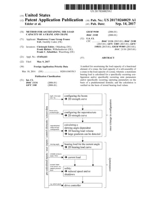
10138] FIG . 10 shows a flow diagram for calculating a
bearing load volume.Asshown in the stepsatthetop ofFIG .
10,the configuration is initially determined once when there
is a change in the configuration, see the top two steps. The
configuration of the boom and the configuration of the
superstructure are for example determined, and a strength
curve orbearing load curve is ascertained in each casewhich
can be two-dimensional ormulti-dimensional. As indicated
by way of example,state parameters oftheboom are (not
exhaustively) the angle,the telescopic stateand thetip.State
parameters of the superstructure are for example (likewise
not exhaustively) the curve of the boom , the current coun
terweight and the state of the lift mechanism . The under
carriage configuration can assume a theoretically infinite
number ofstates due to the variable support breadth of the
outriggers, wherein the load capacity is calculated for the
specifically occurring statewhich is forexampleascertained
automatically on the basis of the sensors, provided on the
supportmembers, for determining the respective extended
state. In combination with the strength curves of the boom
and superstructure which are ascertained from stored values,
it is possible to calculate a maximum load capacity which is
dependent on the slewing angle, such that a three-dimen
sional bearing load volume can for example be produced,
wherein large gradients can also be detected. In this context,
gradients can for example indicate how significantly the
bearing load is changed by changing parameters. The latter
are very important for safe operations and can also be
separately assessed. For particular configurations (for
example, all outriggermembers retracted), itmay be that a
bearing load of 15 t is permissible at a given slewing angle
of the superstructure of for example 80°. It may then be that
at a slewing angle of759, the permissible load shrinks to 5
t due to restrictions relating to structural integrity, i.e. the
" change in bearing load per change in angle” gradientin this
case is 10/5 = 2.0 t/°. For dynamic and control-related rea
sons, however, a certain "precursor angle” is necessary
which has to be available for the targeted deceleration of the
superstructure. If this precursor angle is 10°, then measures
would therefore have to be initiated, atthe earliest even at
850, so that the 5 t point is not exceeded at 75° even when
the slewing ofthe superstructure is braked sharply.
[0139] Once themaximum bearing load hasbeen ascer
tained and calculated once for a present configuration or
following a change in the configuration, the subsequent
steps can be performed continuously oron an ongoingbasis
during operations. The respectively permissible maximum
bearing load can be determined for the current slewing angle
between the superstructure and the undercarriage, which is
for example ascertained by means of a slewing angle sensor.
This then results in a two-dimensional load -over-radius
bearing load curve which for example shows the bearing
load for various derricking angles (radii).
[0140] In consideration of a measured or inputted current
load, which is for example ascertained on the basis of the
parameters ofcylinderpressure, angle and/or force, a cal
16. US 2017/0260029 A1 Sep. 14, 2017
culation canbemade in order to indicate to an operatorthat
the speed should be reduced or the crane should be shut
down into a secure mode. This information can also be
converted automatically into the actions indicated,wherein
for example the output value of a wind sensor and/or a
supportpressure limit and/or a user input can be considered .
[0141] This information can be forwarded to a drive
controller in order to operate the crane.
1 -15 . (canceled)
16. A method for ascertaining a load capacity of a crane
in a particular configuration, wherein :
a) the crane comprises at least two sub-assemblies;
b) thecrane exhibits a plurality ofpossible configurations
which are determined by parameters of the sub-assem
blies;
c) the sub-assembly-specific load capacity ofthe crane is
dependent on at least one parameter of the respective
sub-assembly;
d) at least one first sub-assembly is specified by a lowest
number ofparameters and/or exhibits a lowestnumber
of possible variations of the parameter or parameters
and/orexhibits a lowest gradient of the change in the
maximum bearing load when there is a change in one
ormore parameters;
e) at least one second sub-assembly is specified by a
largest number of parameters and/or exhibits a largest
number of possible variations of the parameter or
parameters and/or exhibits a largest gradient of the
change in themaximum bearing load when there is a
change in one ormore parameters;
f) the specifically occurring values of the parameters of
the at least one first sub -assembly and the at least one
second sub-assembly are ascertained in the particular
configuration of the crane;
g) the sub-assembly-specific load capacity of the atleast
one first sub-assembly is calculated and/or pre-deter
mined and stored as a function of at least one of the
parameters ofthe at least one firstsub-assembly and is
read out for the specifically occurring value(s) of the
parameter(s) from a memory;
h )the sub-assembly-specific load capacity of the at least
one second sub-assembly is ascertained or calculated
from the specifically occurring values of the parameter
orparametersofthe second sub-assembly,wherein the
result of ascertaining or calculating is verified on the
basis ofone ormore stored values; and
i)the load capacity ofthe crane isdeterminedon thebasis
of the sub-assembly -specific load capacities of the at
least one first sub -assembly and theat least one second
sub-assembly thus ascertained.
17. The method for ascertaining the load capacity of a
crane according to claim 16 , wherein the first sub -assembly
is a sub-assemblywhich is dependenton one parameteronly.
18. The method for ascertaining the load capacity of a
crane according to claim 16,wherein the first sub-assembly
is a sub-assembly which is dependent on two parameters at
most or three parameters atmost.
19. The method for ascertaining the load capacity of a
crane according to claim 16, wherein the second sub
assembly is a sub-assembly which is dependent on four or
more parameters and/or is an undercarriage comprising
support elements which can be extended independently of
each other.
20. The method for ascertaining the load capacity of a
crane according to claim 16 , wherein the second sub
assembly is a sub -assembly which is dependent on at least
three parameters or at least four parameters, wherein each
parameterof thesub-assembly can be discretely or continu
ously changed independently of other parameters of the
sub-assembly.
21. The method for ascertaining the load capacity of a
crane according to claim 16, wherein parameters of a
sub-assemblyofthe at leasttwo sub-assemblies include state
parameters for describing the state or determining the con
figuration or geometry ofthesub-assembly and/or operating
parameters for describing the operating state.
22. The method for ascertaining the load capacity of a
crane according to claim 16 , wherein the at least two
sub -assemblies are used to perform the method, the at least
two sub-assemblies including at least two of: a boom
sub -assembly; a derricking cylindersub -assembly, a support
sub-assembly;a counterweight sub-assembly; an undercar
riage sub-assembly; and a superstructure sub-assembly.
23. The method for ascertaining the load capacity of a
crane according to claim 22,wherein:
theboom sub-assembly is determined by the parameters
of boom length and/or boom angle; and/or
thederricking cylinder sub-assembly is determined by the
parameter ofboom length or optionally boom angle,
from kinematics; and/or
theundercarriage sub-assembly comprisesof at leastfour
individual supportmembers or individual supports and
is determined by the parameterof length of extension
and/or the parameter of support force which can be
determined independently of each other for each indi
vidual support member or each individual support;
and/or
the counterweight sub-assembly is determined by the
parameterofweightvalue and location ofthe centre of
gravity; and/or
a crane sub-assembly is determinedby the parameters of
theboom sub-assembly, the derricking cylinder sub
assembly, thesupportmembersub-assembly,thecoun
terweight sub-assembly and the superstructure sub
assembly.
24. The method for ascertaining the load capacity of a
crane according to claim 16 ,wherein thespecifically occur
ring value of the parameter or parameters of a sub -assembly
of the at least two sub-assemblies is ascertained by one or
more sensors and/or by manual inputs.
25 . A method for ascertaining the load capacity of a
functional elementof a crane, the load capacity of a sub
assembly of a crane or theload capacity of a crane,wherein :
a maximum bearing load is calculated for a specifically
occurring configuration and/or specifically occurring
state parameters and/or specifically occurring operating
parameters on the basis of a predetermined formula ;
and
the calculation is verified on the basis ofstored bearing
load values.
26 . The method according to claim 25, wherein in order
to verify a calculation, the stored parameter sets which
match the given parameter values and/or exhibit a minimal
upward and/or downward deviation for a respective param
eter are adduced.
27. Themethod according to claim 25, wherein a verifi
cation is made, on the basis of a gradient observation
17. US 2017/0260029 A1 Sep. 14, 2017
ascertained on the basis of the stored values, as to whether
a calculated bearing load value is plausible.
28. A method formonitoring a crane, wherein the load
capacity of a crane is ascertained using amethod according
to 25 and monitored as to whether it is being observed.
* * * * *