SlideShare a Scribd company logo
1 of 12
Download to read offline
INTAKE MANIFOLD
           EXHAUST PIPE
               MUFFLER      CATALYTIC CONVERTER TAILPIPE
                                           EXHAUST MANIFOLD


XJ                                                             EXHAUST SYSTEM AND INTAKE MANIFOLD                                      11 - 1


                 EXHAUST SYSTEM AND INTAKE MANIFOLD
                                                      CONTENTS

                                                        page                                                                               page

GENERAL INFORMATION                                             EXHAUST MANIFOLD—4.0L ENGINE                       .   .   .   .   .   .   .   .   8
  CATALYTIC CONVERTER . . . . . . . .        ......... 1        EXHAUST PIPE . . . . . . . . . . . . . . . .   .   .   .   .   .   .   .   .   .   2
  EXHAUST SYSTEM . . . . . . . . . . . . .   ......... 1        INTAKE MANIFOLD—2.5L ENGINE .                  .   .   .   .   .   .   .   .   .   5
DIAGNOSIS AND TESTING                                           INTAKE MANIFOLD—4.0L ENGINE .                  .   .   .   .   .   .   .   .   .   6
  EXHAUST SYSTEM DIAGNOSIS . . .             ......... 2        MUFFLER AND EXHAUST TAILPIPE                   .   .   .   .   .   .   .   .   .   4
REMOVAL AND INSTALLATION                                       SPECIFICATIONS
  CATALYTIC CONVERTER . . . . . . . .        ......... 3        TORQUE SPECIFICATIONS . . . . . . .            ......... 8
  EXHAUST MANIFOLD—2.5L ENGINE                ........ 8

GENERAL INFORMATION                                               The 4.0L engines use a seal between the engine
                                                               exhaust manifold and exhaust pipe to assure a tight
EXHAUST SYSTEM                                                 seal and strain free connections.
  The basic exhaust system consists of an engine                  The exhaust system must be properly aligned to
exhaust manifold, exhaust pipe with oxygen sensor,             prevent stress, leakage and body contact. If the sys-
catalytic converter with oxygen sensor, muffler and            tem contacts any body panel, it may amplify objec-
exhaust tailpipe (Fig. 1).                                     tionable noises originating from the engine or body.
                                                                  When inspecting an exhaust system, critically
                                                               inspect for cracked or loose joints, stripped screw or
                                                               bolt threads, corrosion damage and worn, cracked or
                                                               broken hangers. Replace all components that are
                                                               badly corroded or damaged. DO NOT attempt to
                                                               repair.
                                                                  When replacement is required, use original equip-
                                                               ment parts (or their equivalent). This will assure
                                                               proper alignment and provide acceptable exhaust
                                                               noise levels.

                                                               CAUTION: Avoid application of rust prevention
                                                               compounds or undercoating materials to exhaust
                                                               system floor pan exhaust heat shields. Light over
                                                               spray near the edges is permitted. Application of
                                                               coating will result in excessive floor pan tempera-
                                                               tures and objectionable fumes.


                                                               CATALYTIC CONVERTER
                                                                  The stainless steel catalytic converter body is
                                                               designed to last the life of the vehicle. Excessive heat
                                                               can result in bulging or other distortion, but exces-
                                                               sive heat will not be the fault of the converter. If
                                                               unburned fuel enters the converter, overheating may
                                                               occur. If a converter is heat-damaged, correct the
                                                               cause of the damage at the same time the converter
                                                               is replaced. Also, inspect all other components of the
                                                               exhaust system for heat damage.
            Fig. 1 Exhaust System—Typical                         Unleaded gasoline must be used to avoid contami-
   The exhaust system uses a single muffler with a             nating the catalyst core.
catalytic converter consisting of dual ceramic mono-
liths.
11 - 2   EXHAUST SYSTEM AND INTAKE MANIFOLD                                                                   XJ


DIAGNOSIS AND TESTING
EXHAUST SYSTEM DIAGNOSIS

CAUTION: When servicing and replacing exhaust components, disconnect the oxygen sensor connectors.
Allowing the exhaust to hang by the oxygen sensor wires will damage the harness and/or sensor.

CONDITION                           POSSIBLE CAUSE                         CORRECTION
EXCESSIVE EXHAUST NOISE OR          1. Leaks at pipe joints.               1. Tighten clamps/bolts at leaking
LEAKING EXHAUST GASES                                                      joints.
                                    2. Rusted or blown out muffler.        2. Replace muffler. Inspect exhaust
                                                                           system.
                                    3. Broken or rusted out exhaust pipe. 3. Replace exhaust pipe.
                                    4. Exhaust pipe leaking at manifold    4. Tighten/replace flange attaching
                                    flange.                                nuts/bolts.
                                    5. Exhaust manifold cracked or         5. Replace exhaust manifold.
                                    broken.
                                    6. Leak between exhaust manifold       6. Tighten exhaust manifold to
                                    and cylinder head.                     cylinder head bolts.
                                    7. Catalytic converter rusted or blown 7. Replace catalytic converter assy.
                                    out.
                                    8. Restriction in exhaust system.      8. Remove restriction, if possible.
                                                                           Replace restricted part if necessary.


REMOVAL AND INSTALLATION                                  apply heat until the metal becomes cherry red. Dis-
                                                          connect the exhaust pipe from the catalytic converter
EXHAUST PIPE                                              (Fig. 2). Remove the exhaust pipe.

WARNING: IF TORCHES ARE USED WHEN WORK-                   INSTALLATION
ING ON THE EXHAUST SYSTEM, DO NOT ALLOW                      (1) Assemble exhaust pipe to manifold and cata-
THE FLAME NEAR THE FUEL LINES.                            lytic converter loosely to permit proper alignment of
                                                          all parts.
                                                             (2) Use a new clamp and tighten the nuts to 61
CAUTION: When servicing exhaust system compo-             N·m (45 ft. lbs.) torque.
nents, disconnect the oxygen sensor connector.               (3) Connect the exhaust pipe to the engine exhaust
Allowing the exhaust system to hang by the oxygen         manifold. Install a new seal between the exhaust
sensor harness will damage the wiring and/or sen-         manifold and the exhaust pipe (4.0L engine only).
sor.                                                      Tighten the nuts to 31 N·m (23 ft. lbs.) torque (Fig.
                                                          2).
                                                             (4) Install the rear crossmember. Install and
REMOVAL
                                                          tighten the four (4) crossmember to rear mount nuts
  (1) Raise and support the vehicle.
                                                          to 22 N·m (16 ft. lbs.) Install and tighten the cross-
  (2) Saturate the bolts and nuts with heat valve
                                                          member to sill bolts to 42 N·m (31 ft. lbs.) torque.
lubricant (Fig. 2). Allow 5 minutes for penetration.
                                                          Remove the support from the transmission.
  (3) Disconnect the oxygen sensor connector (Fig.
                                                             (5) Coat the oxygen sensor with anti-seize com-
3).
                                                          pound. Install the sensor and tighten the nut to 27
  (4) Disconnect the exhaust pipe from the engine
                                                          N·m (20 ft. lbs.) torque.
exhaust manifold. Discard the seal (4.0L engine,
                                                             (6) Lower the vehicle.
only).
                                                             (7) Start the engine and inspect for exhaust leaks
  (5) Support the transmission and remove the rear
                                                          and exhaust system contact with the body panels.
crossmember.
                                                          Adjust the alignment, if needed.
  (6) Remove the clamp nuts and clamp (Fig. 2). To
remove the exhaust pipe from the catalytic converter,
SEAL (4.0L)
        MANIFOLD
           NUT UPSTREAM SENSOR
                    GEN    OXY-   DOWNSTREAM OXY-
                                        GEN SENSOR   EXHAUST PIPE
                                                      TRANSMISSION   TRANSMISSION
                                                                      SUPPORT
                                                                      BRACKET       CLAMP CATALYTIC CONVERTERCATALYTIC CONVERTER
                                                                                    SUPPORT
                                                                                     BRACKET
                                                                                       EXHAUST PIPE       CLAMPS                MUFFLER


XJ                                                               EXHAUST SYSTEM AND INTAKE MANIFOLD                            11 - 3
REMOVAL AND INSTALLATION (Continued)


                                         Fig. 2 Exhaust Pipe Removal—2.5L/4.0L
                                                                     REMOVAL
                                                                       (1) Raise and support the vehicle.
                                                                       (2) Remove the clamps from the catalytic converter
                                                                     and muffler connection (Fig. 4).
                                                                       (3) Disconnect and remove the oxygen sensor from
                                                                     the catalytic converter.
                                                                       (4) Heat the catalytic converter and muffler con-
                                                                     nection with an oxyacetylene torch until the metal
                                                                     becomes cherry red.
                                                                       (5) While the metal is still cherry red, twist the
                                                                     muffler assembly back and forth to separate it from
                                                                     the catalytic converter.
                                                                       (6) Disconnect the exhaust pipe from the catalytic
                                                                     converter (Fig. 4). If needed, heat up the pipes to sep-
                                                                     arate.

            Fig. 3 Oxygen Sensor Location
CATALYTIC CONVERTER
WARNING: IF TORCHES ARE USED WHEN WORK-
ING ON THE EXHAUST SYSTEM, DO NOT ALLOW
THE FLAME NEAR THE FUEL LINES.


CAUTION: When servicing exhaust system compo-
nents, disconnect the oxygen sensor connector.
Allowing the exhaust system to hang by the oxygen
sensor harness will damage the wiring and/or sen-
sor.


                                                                      Fig. 4 Catalytic Converter to Muffler and Exhaust
                                                                                       Pipe Connection
FRONT   MUFFLER
                                                                         TAILPIPE
                                                                         HANGER     CATALYTIC CONVERTER
                                                                                                 INSULATOR CLAMP
                                                                                                       TAILPIPE MUFFLER


11 - 4    EXHAUST SYSTEM AND INTAKE MANIFOLD                                                                              XJ
REMOVAL AND INSTALLATION (Continued)
INSTALLATION
  (1) Connect the catalytic converter to the exhaust
pipe and the muffler/tailpipe assy. (Fig. 4). Use a new
clamp and tighten the nuts to 61 N·m (45 ft. lbs.)
torque.
  (2) Install the muffler onto the catalytic converter
until the alignment tab is inserted into the align-
ment slot.
  (3) Install a new clamp at the muffler and cata-
lytic converter connection (Fig. 4). Tighten the clamp
nut to 61 N·m (45 ft. lbs.) torque.
  (4) Coat the oxygen sensor with anti-seize com-
pound. Install the sensor and tighten the nut to 27
N·m (20 ft. lbs.) torque.
  (5) Lower the vehicle.
  (6) Start the engine and inspect for exhaust leaks
and exhaust system contact with the body panels.
Adjust the alignment, if needed.

MUFFLER AND EXHAUST TAILPIPE
   All original equipment exhaust systems are manu-
factured with the exhaust tailpipe welded to the muf-
fler. Service replacement mufflers and exhaust                    Fig. 5 Front Exhaust Tailpipe Hanger
tailpipes are either clamped together or welded
together.

WARNING: IF TORCHES ARE USED WHEN WORK-
ING ON THE EXHAUST SYSTEM, DO NOT ALLOW
THE FLAME NEAR THE FUEL LINE.


CAUTION: When servicing exhaust system compo-
nents, disconnect the oxygen sensor connector.
Allowing the exhaust system to hang by the oxygen
sensor harness will damage the wiring and/or sen-
sor.


REMOVAL
   (1) Raise and support the vehicle.
   (2) Disconnect front tailpipe hanger from the insu-      Fig. 6 Catalytic Converter to Muffler Connection
lator (Fig. 5).
   (3) Remove the front exhaust clamp from the cat-       close to the muffler. Collapse the part remaining in
alytic converter and muffler connection (Fig. 6).         the muffler and remove.
   (4) Heat the catalytic converter-to-muffler connec-       • To remove a service exhaust tailpipe/muffler
tion with an oxyacetylene torch until the metal           combination, apply heat until the metal becomes
becomes cherry red.                                       cherry red. Remove the exhaust tailpipe/muffler
   (5) While the metal is still cherry red, remove the    clamp and twist the exhaust tailpipe out of the muf-
exhaust muffler/tailpipe assembly from the catalytic      fler.
converter.                                                   (8) If the tailpipe is also to be replaced
   (6) Slide the muffler/tailpipe assy. rearward and
                                                          INSTALLATION
out of the rear exhaust tailpipe mounting bracket
                                                            (1) Install the muffler onto the catalytic converter.
(Fig. 7).
                                                          Install the clamp and tighten the nuts finger tight.
   (7) Remove the muffler from the exhaust tailpipe:
                                                            (2) Install the exhaust tailpipe into the rear of the
   • To remove an original equipment exhaust muf-
                                                          muffler.
fler/tailpipe combination, cut the exhaust tailpipe
                                                            (3) Install the exhaust tailpipe/muffler assembly
                                                          on the rear exhaust tailpipe mounting bracket. Make
MUFFLER/TAILPIPE ASSEM-
     TAILPIPE BRACKET BLY
           ING MOUNT-


XJ                                                       EXHAUST SYSTEM AND INTAKE MANIFOLD             11 - 5
REMOVAL AND INSTALLATION (Continued)
                                                         stallation (refer to Group 14, Fuel System - Quick
                                                         Connect Fittings).
                                                           (7) Disconnect the accelerator cable, the cruise
                                                         control cable (if equipped), and the transmission line
                                                         pressure cable (if equipped) from the throttle body
                                                         and remove them from the cable bracket.

                                                         CAUTION: When disconnecting the cruise control
                                                         connector at the throttle body, DO NOT pry the con-
                                                         nector off with pliers or screwdriver. Use finger
                                                         pressure only. Prying the connector off could break
                                                         it.

                                                            (8) Disconnect the electrical connectors. Pull the
                                                         harnesses away from the manifold and secure them
                                                         so they do not interfere with the manifold removal
                                                         and installation process.
                                                            • The throttle position sensor.
                                                            • The idle air control motor.
                                                            • The coolant temperature sensor at the thermo-
                                                         stat.
                                                            • The manifold air temperature sensor at the
   Fig. 7 Rear Exhaust Tailpipe Mounting Bracket         intake manifold.
                                                            • The fuel injectors.
sure that the exhaust tailpipe has sufficient clear-        • The oxygen sensor.
ance from the floor pan.                                    (9) Disconnect the crankcase ventilation (CCV)
  (4) Install front tailpipe hanger into the insulator   vacuum hose and manifold absolute pressure (MAP)
(Fig. 5).                                                sensor vacuum hose connector at the intake mani-
  (5) Align the muffler and tighten the nuts on the      fold.
muffler-to-catalytic converter clamp to 61 N·m (45 ft.      (10) Disconnect vacuum hose from vacuum port on
lbs.) torque (Fig. 6).                                   the intake manifold.
  (6) Align the tailpipe and install a new clamp at         (11) Disconnect CCV hose at the cylinder head
the muffler to tailpipe connection.                      cover (Fig. 8).
  (7) Tighten the muffler to tailpipe clamp to 61 N·m       (12) Remove the molded vacuum harness.
(45 ft. lbs.)                                               (13) Disconnect the vacuum brake booster hose at
  (8) Lower the vehicle.                                 the intake manifold.
  (9) Start the engine and inspect for exhaust leaks        (14) Remove bolts 2 through 5 securing the intake
and exhaust system contact with the body panels.         manifold to the cylinder head (Fig. 11). Slightly
Adjust the alignment, if needed.                         loosen bolt No.1 and nuts 6 and 7.
                                                            (15) Remove the intake manifold and gaskets.
INTAKE MANIFOLD—2.5L ENGINE                              Drain the coolant from the manifold.
REMOVAL                                                  INSTALLATION
  (1) Disconnect the battery negative cable.                (1) Clean the intake manifold and cylinder head
  (2) Remove the air inlet hose from the throttle        mating surfaces. DO NOT allow foreign material
body and air cleaner.                                    to enter either the intake manifold or the ports
  (3) Loosen the accessory drive belt tension and        in the cylinder head.
remove the belt from the power steering pump (refer         (2) Install the new intake manifold gasket over the
to Group 07, Cooling Systems for proper procedures).     locating dowels.
  (4) Remove the power steering pump and brackets           (3) Position the manifold in place and finger
from the water pump and intake manifold. Secure          tighten the mounting bolts.
power steering pump and bracket out of the way.             (4) Tighten the fasteners in sequence and to the
  (5) Perform fuel system pressure release procedure     specified torque (Fig. 11).
(refer to Group 14, Fuel System for correct proce-          • Fastener No.1—Tighten to 41 N·m (30 ft. lbs.)
dure).                                                   torque.
  (6) Disconnect fuel supply tube from the fuel rail.       • Fasteners Nos.2 through 7—Tighten to 31 N·m
Some fuel lines require a special tool for removal/in-   (23 ft. lbs.) torque.
FIXED
     AIR   ORIFICE INLET TING
           FITTING
              AIR
               COVER
                FILTER    FIT-


11 - 6      EXHAUST SYSTEM AND INTAKE MANIFOLD                                                               XJ
REMOVAL AND INSTALLATION (Continued)
                                                            (13) Install and tension the accessory drive belt.
                                                          Refer to Group 7, Cooling System for the proper pro-
                                                          cedure.

                                                          CAUTION: Ensure that the accessory drive belt is
                                                          routed correctly. Failure to do so can cause the
                                                          water pump to turn in the opposite direction result-
                                                          ing in engine overheating. Refer to Group 7, Cool-
                                                          ing System for the proper procedure.

                                                            (14) Connect the air inlet hose to the throttle body
                                                          and the air cleaner.
                                                            (15) Connect the battery negative cable.
                                                            (16) Start the engine and check for leaks.

                                                          INTAKE MANIFOLD—4.0L ENGINE
                                                            The intake and engine exhaust manifolds on the
                                                          4.0L engine must be removed and installed together.
                                                          The two manifolds use a common gasket at the cyl-
                                                          inder head.

                                                          REMOVAL
                                                             (1) Disconnect the battery negative cable.
   Fig. 8 Crankcase Ventilation (CCV) Hose—2.5L
                                                             (2) Remove air cleaner inlet hose from throttle
                      Engine
                                                          plate assembly.
   (5) Connect fuel supply tube to the fuel rail inlet.      (3) Remove the air cleaner assembly.
Push tube until a “click” is heard. Before connect-          (4) Remove the throttle cable, cruise control cable
ing the fuel line to the fuel rail replace the            (if equipped) and the transmission line pressure
O-rings at the quick-connect fuel line coupling.          cable.
   (6) Pull out on the fuel supply tube to ensure that       (5) Disconnect the crankcase ventilation (CCV)
it is locked in place.                                    vacuum hose and manifold absolute pressure (MAP)
   (7) Connect the molded vacuum hoses to the vac-        sensor vacuum hose connector at the intake mani-
uum port on the intake manifold and the cylinder          fold.
head cover.                                                  (6) Disconnect vacuum hose from vacuum port on
   (8) Connect the electrical connectors.                 the intake manifold.
   • The throttle position sensor.                           (7) Disconnect CCV hose at the cylinder head
   • The idle air control motor.                          cover (Fig. 9).
   • The coolant temperature sensor at the thermo-           (8) Perform fuel system pressure release procedure
stat housing.                                             (refer to Group 14, Fuel System for correct proce-
   • The fuel injectors.                                  dure).
   • The air manifold temperature sensor.                    (9) Remove fuel supply line latch clip at injector
   • The oxygen sensor.                                   rail.
   (9) Connect the CCV vacuum hose and MAP sen-              (10) Disconnect fuel supply tube from the fuel rail.
sor vacuum hose connectors to the throttle body.          Some fuel lines require a special tool for removal/in-
   (10) Install the power steering pump and bracket       stallation (refer to Group 14, Fuel System - Quick
assembly to the water pump and intake manifold.           Connect Fittings).
Hand start the three (3) tensioner bracket to p/s            (11) Disconnect all electrical connectors on the
pump to intake manifold bolts and the two (2) ten-        intake manifold.
sioner bracket to water pump bolts.                          • The throttle position sensor.
   (11) Tighten the power steering pump bolts to 28          • The idle air control motor.
N·m (21 ft. lbs.) Tighten the tensioner bracket to           • The coolant temperature sensor at the thermo-
water pump bolts to 28 N·m (21 ft. lbs.).                 stat.
   (12) Connect the accelerator cable, cruise control        • The manifold air temperature sensor at the
cable (if equipped), and the transmission line pres-      intake manifold.
sure cable (if equipped) to the hold-down bracket and        • The fuel injectors.
the throttle lever.                                          • The oxygen sensor.
AIR    INLET TING
              FIT-   FWDIXED
                       F       ORIFICE
                               FITTING
                                AIR      COVER
                                         FILTER                    CYLINDER HEAD DOWEL   EXHAUST   INTAKE
                                                                                                   MANI-
                                                                                                     MANI-
                                                                                                     FOLD
                                                                                                       FOLD   CYLINDER
                                                                                                              HEADDOWEL


XJ                                                         EXHAUST SYSTEM AND INTAKE MANIFOLD                     11 - 7
REMOVAL AND INSTALLATION (Continued)
                                                              (8) Tighten the fasteners in sequence and to the
                                                           specified torque (Fig. 10).
                                                              • Fasteners Nos.1 through 5—Tighten to 33 N·m
                                                           (24 ft. lbs.) torque.
                                                              • Fasteners Nos.6 and 7—Tighten to 31 N·m (23
                                                           ft. lbs.) torque.
                                                              • Fasteners Nos.8 through 11—Tighten to 33 N·m
                                                           (24 ft. lbs.) torque.


      Fig. 9 Crankcase Ventilation (CCV) Hose —4.0L
                         Engine
                                                            Fig. 10 Intake/Engine Exhaust Manifold Installation
  (12) Loosen the accessory drive belt tension and                             (4.0L Engine)
remove the belt from the power steering pump (refer
to Group 07, Cooling Systems for proper procedures).          (9) Install the power steering pump and bracket to
  (13) Remove the power steering pump and bracket          the intake manifold and water pump. Tighten the
from the intake manifold and water pump and set            belt to specification (Refer to Group 7, Cooling Sys-
aside.                                                     tem for the proper procedures).
  (14) Raise the vehicle.                                     (10) Connect fuel supply tube to the fuel rail inlet.
  (15) Disconnect the exhaust pipe from the engine         Push tube until a “click” is heard. Before connect-
exhaust manifold. Discard the seal.                        ing the fuel line to the fuel rail replace the
  (16) Lower the vehicle.                                  O-rings at the quick-connect fuel line coupling.
  (17) Remove the intake manifold and engine                  (11) Pull out on the fuel supply tube to ensure that
exhaust manifold.                                          it is locked in place.
                                                              (12) Replace latch clip.
INSTALLATION                                                  (13) Connect all electrical connections on the
   (1) Clean the mating surfaces of the cylinder head      intake manifold.
and the manifold if the original manifold is to be re-        (14) Connect the vacuum connector on the intake
installed.                                                 manifold and install it in the bracket.
   (2) If the manifold is being replaced, ensure all the      (15) Install throttle cable, cruise control cable (if
sensors, fittings, etc. are transferred to the replace-    equipped).
ment manifold.                                                (16) Install the transmission line pressure cable (if
   (3) Install a new exhaust/intake manifold gasket        equipped). Refer to Group 21, Transmission for the
over the alignment dowels on the cylinder head.            adjustment procedures.
   (4) Position the engine exhaust manifold to the            (17) Install air cleaner assembly.
cylinder head. Install fastener No.3 and finger               (18) Connect air inlet hose to the throttle plate
tighten at this time (Fig. 10).                            assembly.
   (5) Install intake manifold on the cylinder head           (19) Raise the vehicle on a side mounted hoist.
dowels.                                                       (20) Using a new seal, connect the exhaust pipe to
   (6) Install washers and fasteners Nos.1, 2, 4, 5, 8,    the engine exhaust manifold. Tighten the bolts to 31
9, 10 and 11 (Fig. 10).                                    N·m (23 ft. lbs.) torque.
   (7) Install washers and fasteners Nos.6 and 7 (Fig.        (21) Lower the vehicle.
10).                                                          (22) Connect the battery negative cable.
                                                              (23) Start the engine and check for leaks.
SPACER
      EXHAUST   MANI-
                FOLD    CYLINDER HEAD DOWELS
                                         INTAKE   MANI-
                                                  FOLDSPACER


11 - 8    EXHAUST SYSTEM AND INTAKE MANIFOLD                                                                                       XJ
REMOVAL AND INSTALLATION (Continued)
EXHAUST MANIFOLD—2.5L ENGINE                                     (8) Tighten nuts 6 and 7 to 31 N·m (23 ft. lbs.)
                                                               torque (Fig. 11).
REMOVAL                                                          (9) Install all components to the intake manifold.
  (1) Disconnect the battery negative cable.                     (10) Raise the vehicle.
  (2) Raise the vehicle.                                         (11) Connect the exhaust pipe to the engine
  (3) Disconnect the exhaust pipe from the engine              exhaust manifold. Tighten the bolts to 31 N·m (23 ft.
exhaust manifold.                                              lbs.) torque.
  (4) Lower the vehicle.                                         (12) Lower the vehicle.
  (5) Remove intake manifold (refer to procedure in              (13) Connect the battery negative cable.
this section)                                                    (14) Start the engine and check for leaks.
  (6) Remove fasteners 2 through 5 and remove the
intake manifold (Fig. 11).                                     EXHAUST MANIFOLD—4.0L ENGINE
  (7) Remove fasteners 1, 6 and 7 and remove the                  The intake and engine exhaust manifolds on the
engine exhaust manifold (Fig. 11).                             4.0L engine must be removed and installed together.
                                                               The manifolds use a common gasket at the cylinder
                                                               head.
                                                                  Refer to Intake Manifold—4.0L Engine in this sec-
                                                               tion for the proper removal and installation proce-
                                                               dures.


                                                               SPECIFICATIONS
                                                               TORQUE SPECIFICATIONS

                                                               Description                                                   Torque
                                                               Catalytic Converter/Exhaust Pipe
                                                               Exhaust Clamp Nut . . . . . . . . . . 61 N·m               (45 ft. lbs.)
                                                               Crossmember to Sill
                                                               Bolts . . . . . . . . . . . . . . . . . . . . . . 42 N·m   (31 ft. lbs.)
      Fig. 11 Intake/Exhaust Manifold Removal/                 Crossmember to Transmission Mount
               Installation—2.5L Engine                        Nuts . . . . . . . . . . . . . . . . . . . . . . 22 N·m    (16 ft. lbs.)
                                                               Exhaust Pipe to Manifold
INSTALLATION                                                   Nuts . . . . . . . . . . . . . . . . . . . . . . 31 N·m    (23 ft. lbs.)
  (1) Clean the intake and engine exhaust manifolds
                                                               Exhaust Manifold–2.5L Engine
and cylinder head mating surfaces. DO NOT allow
                                                               Bolt #1 . . . . . . . . . . . . . . . . . . . . 41 N·m     (30 ft. lbs.)
foreign material to enter either the intake man-
                                                               Exhaust Manifold–2.5L Engine
ifold or the ports in the cylinder head.
                                                               Bolts #2–5 . . . . . . . . . . . . . . . . . . 31 N·m      (23 ft. lbs.)
  (2) Install a new intake manifold gasket over the
alignment dowels on the cylinder head.                         Exhaust Manifold–4.0L Engine
  (3) Install the engine exhaust manifold assembly.            Nuts/Bolts #1–5 & #8–11 . . . . . . 33 N·m                 (24 ft. lbs.)
Exhaust manifold must be centrally located                     Exhaust Manifold–2.5L Engine
over the end studs and spacer (Fig. 11).                       Nuts #6&7 . . . . . . . . . . . . . . . . . 31 N·m         (23 ft. lbs.)
  (4) Tighten bolt No.1 to 41 N·m (30 ft. lbs.) torque         Exhaust Manifold–4.0L Engine
(Fig. 11).                                                     Nuts #6&7 . . . . . . . . . . . . . . . . . 31 N·m         (23 ft. lbs.)
  (5) Install the intake manifold on the cylinder              Intake Manifold–2.5L Engine
head dowels (Fig. 11).                                         Bolt #1 . . . . . . . . . . . . . . . . . . . . 41 N·m     (30 ft. lbs.)
  (6) Install bolts 2 through 5 (Fig. 11). Tighten             Intake Manifold–2.5L Engine
these bolts to 31 N·m (23 ft. lbs.) torque.                    Bolt #2–5 . . . . . . . . . . . . . . . . . . 31 N·m       (23 ft. lbs.)
  (7) Install new engine exhaust manifold spacers              Muffler to Catalytic Converter
over the engine exhaust manifold mounting studs in             Exhaust Clamp Nut . . . . . . . . . . 61 N·m               (45 ft. lbs.)
the cylinder head (Fig. 11).                                   Oxygen Sensors
                                                               Nut . . . . . . . . . . . . . . . . . . . . . . . 27 N·m   (20 ft. lbs.)
                                                               Rear Tail Pipe Hanger
                                                               Nuts . . . . . . . . . . . . . . . . . . . . . . 54 N·m    (40 ft. lbs.)
XJ                                                              EXHAUST SYSTEM AND INTAKE MANIFOLD                   11 - 1


                EXHAUST SYSTEM AND INTAKE MANIFOLD
                                                      CONTENTS

                                                       page                                                           page

GENERAL INFORMATION                                              EXHAUST PIPE . . . . . . . . . . . . . . .   .......... 1
 EXHAUST HEAT SHIELDS . . . . . . . . . . . . . . . . . 1        INTAKE MANIFOLD . . . . . . . . . . . .      .......... 3
 EXHAUST SYSTEM . . . . . . . . . . . . . . . . . . . . . . 1    MUFFLER AND EXHAUST TAILPIPE                  ......... 2
REMOVAL AND INSTALLATION                                        SPECIFICATIONS
 ENGINE EXHAUST MANIFOLD AND                                     TORQUE SPECIFICATIONS . . . . . .            .......... 4
  TURBOCHARGER . . . . . . . . . . . . . . . . . . . . . 2

GENERAL INFORMATION
EXHAUST SYSTEM
   The basic exhaust system consists of an engine
exhaust manifold, exhaust pipe, exhaust heat
shield(s), muffler and exhaust tailpipe
   The exhaust system uses a single muffler.
   The exhaust system must be properly aligned to
prevent stress, leakage and body contact. If the sys-
tem contacts any body panel, it may amplify objec-
tionable noises originating from the engine or body.
   When inspecting an exhaust system, critically
inspect for cracked or loose joints, stripped screw or
bolt threads, corrosion damage and worn, cracked or
broken hangers. Replace all components that are
badly corroded or damaged. DO NOT attempt to
repair.                                                                            Fig. 1 Heat Shields
   When replacement is required, use original equip-            REMOVAL AND INSTALLATION
ment parts (or equivalent). This will assure proper
alignment and provide acceptable exhaust noise lev-             EXHAUST PIPE
els.
                                                                WARNING: IF TORCHES ARE USED WHEN WORK-
CAUTION: Avoid application of rust prevention                   ING ON THE EXHAUST SYSTEM, DO NOT ALLOW
compounds or undercoating materials to exhaust                  THE FLAME NEAR THE FUEL LINES.
system floor pan exhaust heat shields. Light over-
spray near the edges is permitted. Application of
coating will result in excessive floor pan tempera-             REMOVAL
tures and objectionable fumes.                                    (1) Raise and support the vehicle.
                                                                  (2) Saturate the bolts and nuts at turbo down pipe
                                                                to exhaust pipe with heat valve lubricant. Allow 5
EXHAUST HEAT SHIELDS                                            minutes for penetration..
  Exhaust heat shields are needed to protect both                 (3) Disconnect bolts from exhaust pipe to turbo
the vehicle and the environment from the high tem-              down pipe (Fig. 2).
peratures (Fig. 1).                                               (4) Remove the clamp nuts at muffler (Fig. 3). To
  DO NOT allow the engine to operate at fast idle for           remove the exhaust pipe from the muffler, apply heat
extended periods (over 5 minutes). This condition               until the metal becomes cherry red. Disconnect the
may result in excessive temperatures in the exhaust             exhaust pipe from the muffler. Remove the exhaust
system and on the floor pan.                                    pipe.

                                                                INSTALLATION
                                                                  (1) Assemble exhaust pipe to muffler, loosely to
                                                                permit proper alignment of all parts.
11 - 2   EXHAUST SYSTEM AND INTAKE MANIFOLD                                                                 XJ
REMOVAL AND INSTALLATION (Continued)
                                                        REMOVAL
                                                          (1) Raise and support the vehicle.
                                                          (2) Remove the front muffler clamp from the
                                                        exhaust pipe and muffler connection.
                                                          (3) Remove the rear exhaust tailpipe hanger clamp
                                                        and remove the exhaust tailpipe from the front
                                                        exhaust tailpipe hanger.
                                                          (4) Remove the exhaust tailpipe assembly from the
                                                        muffler.

                                                        INSTALLATION
                                                           (1) Install the muffler onto the exhaust pipe.
                                                        Install the clamp and tighten the nuts finger tight.
                                                           (2) Install the exhaust tailpipe into the rear of the
                                                        muffler.
                                                           (3) Install the exhaust tailpipe/muffler assembly
  Fig. 2 Exhaust Down Pipe to Front Exhaust Pipe        on the rear exhaust tailpipe hanger. Make sure that
                                                        the exhaust tailpipe has sufficient clearance from the
                                                        floor pan.
                                                           (4) Install the remaining clamps and the front
                                                        exhaust tailpipe hanger.
                                                           (5) Tighten the nuts on the muffler-to-exhaust pipe
                                                        clamp to 43 N·m torque.
                                                           (6) Tighten the nuts on the muffler-to-exhaust pipe
                                                        clamp to 43 N·m torque.
                                                           (7) Lower the vehicle.
                                                           (8) Start the engine and inspect for exhaust leaks
                                                        and exhaust system contact with the body panels.
                                                        Adjust the alignment, if needed.

                                                        ENGINE EXHAUST MANIFOLD AND
                                                        TURBOCHARGER
                                                        REMOVAL
            Fig. 3 Front Pipe to Muffler
                                                          (1) Disconnect the battery negative cable.
  (2) Connect the exhaust pipe to the turbo down          (2) Remove air cleaner hoses from turbocharger.
pipe manifold. Tighten the bolts to 22.5 N·m torque.      (3) Remove air cleaner assembly.
  (3) Use a new clamp and tighten the nuts to 43          (4) Remove charge air cooler hoses from turbo-
N·m torque.                                             charger and intake manifold.
  (4) Lower the vehicle.                                  (5) Remove all components attached to the intake
  (5) Start the engine and inspect for exhaust leaks    manifold.
and exhaust system contact with the body panels.          (6) Remove the EGR tube and EGR valve.
Adjust the alignment, if needed.                          (7) Remove exhaust manifold heat shield.
                                                          (8) Remove turbocharger oil feed line (Fig. 4).
MUFFLER AND EXHAUST TAILPIPE                              (9) Remove exhaust down pipe from turbo.
   All original equipment exhaust systems are manu-       (10) Raise the vehicle
factured with the exhaust tailpipe welded to the muf-     (11) Remove oil drain tube from turbocharger
fler. Service replacement mufflers and exhaust            (12) Lower the vehicle
tailpipes are either clamped together or welded           (13) Remove turbocharger and exhaust manifold as
together.                                               an assembly (Fig. 5).

WARNING: IF TORCHES ARE USED WHEN WORK-                 CLEANING
ING ON THE EXHAUST SYSTEM, DO NOT ALLOW                   Clean the exhaust manifold and cylinder head mat-
THE FLAME NEAR THE FUEL LINES.                          ing surfaces.
XJ                                                         EXHAUST SYSTEM AND INTAKE MANIFOLD              11 - 3
REMOVAL AND INSTALLATION (Continued)
                                                              (4) Install exhaust down pipe to turbocharger,
                                                           tighten bolts to 27 N·m.
                                                              (5) Install exhaust heat shield, tighten bolts to 11
                                                           N·m.
                                                              (6) Loose install EGR tube and EGR valve to
                                                           intake manifold.
                                                              (7) Install EGR valve, tighten bolts to 26 N·m.
                                                              (8) Tighten EGR tube nut to 26 N·m.
                                                              (9) Tighten EGR tube flange bolts to 26 N·m.
                                                              (10) Connect all components to intake manifold.
                                                              (11) Connect charge air cooler hoses to turbo-
                                                           charger and intake manifold.
                                                              (12) Install air cleaner assembly.
                                                              (13) Connect air cleaner hose to turbocharger.
                                                              (14) Raise the vehicle
                                                              (15) Install turbocharger drain line.
                                                              (16) Lower the vehicle
                                                              (17) Connect the battery negative cable.
                                                              (18) Start the engine and check for leaks.

                                                           INTAKE MANIFOLD

         Fig. 4 Turbocharger Oil Feed Line                 REMOVAL
                                                             (1) Remove exhaust manifold and turbocharger
INSTALLATION                                               assembly.
   (1) Install turbocharger to exhaust manifold              (2) Remove water manifold.
tighten nuts to 27 N·m.                                      (3) Remove intake manifold.
   (2) Install assembly to engine, tighten nuts to 30
N·m.                                                       CLEANING
                                                             Clean the intake manifold and cylinder head mat-
                                                           ing surfaces. DO NOT allow foreign material to
                                                           enter either the intake manifold or the ports in
                                                           the cylinder head.

                                                           INSTALLATION
                                                              (1) Install the new intake manifold gasket.
                                                              (2) Position the intake manifold in place and fin-
                                                           ger tighten the mounting nuts.
                                                              (3) Tighten the fasteners in sequence and to the
                                                           specified torque 30 N·m.
                                                              (4) Position the water manifold in place and finger
                                                           tighten the mounting nuts.
                                                              (5) Tighten the fasteners to the specified torque 12
                                                           N·m.
                                                              (6) Install exhaust manifold and turbocharger
     Fig. 5 Exhaust Manifold and Turbocharger              assembly.
                                                              (7) Install charge air cooler hose to intake mani-
  (3) Install oil feed line to turbocharger, tighten nut   fold.
to 26 N·m.                                                    (8) Connect the battery negative cable.
                                                              (9) Start engine and check for leaks.
11 - 4       EXHAUST SYSTEM AND INTAKE MANIFOLD                              XJ


SPECIFICATIONS
TORQUE SPECIFICATIONS

Description                                                        Torque
EGR
Attaching Nuts . . . . . . . . . . . . . . . . . . . . . . . 19 N·m
EGR
Tube Nut . . . . . . . . . . . . . . . . . . . . . . . . . . . 34 N·m
EGR
Tube Flange Bolts . . . . . . . . . . . . . . . . . . . . . 26 N·m
Exhaust Manifold
Nuts . . . . . . . . . . . . . . . . . . . . . . . . . . . . . . . 30 N·m
Exhaust Manifold
Heat Shield Nuts . . . . . . . . . . . . . . . . . . . . . 11 N·m
Exhaust Pipe
Support Clamp Bolts . . . . . . . . . . . . . . . . . 22.5 N·m
Exhaust Pipe
Support Clamp Screw . . . . . . . . . . . . . . . . 22.5 N·m
Intake Manifold
Nuts . . . . . . . . . . . . . . . . . . . . . . . . . . . . . . . 30 N·m
Muffler-to-Exhaust Pipe
Clamp Nuts . . . . . . . . . . . . . . . . . . . . . . . . . 43 N·m
Tail Pipe Clamp
Hanger bolt . . . . . . . . . . . . . . . . . . . . . . . . 22.5 N·m
Turbocharger-to-Exhaust manifold
Nuts . . . . . . . . . . . . . . . . . . . . . . . . . . . . . . . 27 N·m
Turbocharger
Oil Feed Line . . . . . . . . . . . . . . . . . . . . . . . 27.4 N·m
Turbocharger Down Pipe-to-Exhaust Pipe
Bolts/Nuts . . . . . . . . . . . . . . . . . . . . . . . . . 22.5 N·m
Turbocharger Down Pipe-to-Turbocharger
Bolts . . . . . . . . . . . . . . . . . . . . . . . . . . . . . . . 27 N·m

More Related Content

Viewers also liked

Diesel Generators & Engines, Caterpillar XQ2000 Power Modules, Natural Gas En...
Diesel Generators & Engines, Caterpillar XQ2000 Power Modules, Natural Gas En...Diesel Generators & Engines, Caterpillar XQ2000 Power Modules, Natural Gas En...
Diesel Generators & Engines, Caterpillar XQ2000 Power Modules, Natural Gas En...Worldwide Power Products
 
Halderman ch024 lecture
Halderman ch024 lectureHalderman ch024 lecture
Halderman ch024 lecturemcfalltj
 
Air Intake & Exhaust System of Automobiles and its Recent Developments
Air Intake & Exhaust System of Automobiles and its Recent DevelopmentsAir Intake & Exhaust System of Automobiles and its Recent Developments
Air Intake & Exhaust System of Automobiles and its Recent DevelopmentsMd. Muntasir R- Rafi
 
Halderman ch023 lecture
Halderman ch023 lectureHalderman ch023 lecture
Halderman ch023 lecturemcfalltj
 
Mill Lubrication System
Mill Lubrication SystemMill Lubrication System
Mill Lubrication SystemAljon Altiche
 
Caterpillar inc
Caterpillar incCaterpillar inc
Caterpillar incknabbey
 
EASA PART 66 Module 15.10 : Lubrication Systems
EASA PART 66 Module 15.10 : Lubrication SystemsEASA PART 66 Module 15.10 : Lubrication Systems
EASA PART 66 Module 15.10 : Lubrication Systemssoulstalker
 
Turbo charger complete prensation
Turbo charger complete prensationTurbo charger complete prensation
Turbo charger complete prensationSwapnil Vhotkar
 
Cooling system
Cooling systemCooling system
Cooling systemAjay Yadav
 
Lubrication system for an automobile
Lubrication system for an automobile Lubrication system for an automobile
Lubrication system for an automobile sgrsoni45
 
Cooling system in Automobiles
Cooling system in AutomobilesCooling system in Automobiles
Cooling system in AutomobilesHarpreet Singh
 
Fuel Injection Systems
Fuel Injection SystemsFuel Injection Systems
Fuel Injection SystemsRajat Seth
 
Reciprocating Piston Engine Lubrication System
Reciprocating Piston Engine Lubrication SystemReciprocating Piston Engine Lubrication System
Reciprocating Piston Engine Lubrication Systemlccmechanics
 
How A Turbo Charger Works
How A Turbo Charger WorksHow A Turbo Charger Works
How A Turbo Charger Worksstooty s
 
Cooling system ppt
Cooling system pptCooling system ppt
Cooling system pptasu21
 

Viewers also liked (20)

Diesel Generators & Engines, Caterpillar XQ2000 Power Modules, Natural Gas En...
Diesel Generators & Engines, Caterpillar XQ2000 Power Modules, Natural Gas En...Diesel Generators & Engines, Caterpillar XQ2000 Power Modules, Natural Gas En...
Diesel Generators & Engines, Caterpillar XQ2000 Power Modules, Natural Gas En...
 
Halderman ch024 lecture
Halderman ch024 lectureHalderman ch024 lecture
Halderman ch024 lecture
 
C18 vs 3408 Caterpillar Engines
C18 vs 3408 Caterpillar Engines C18 vs 3408 Caterpillar Engines
C18 vs 3408 Caterpillar Engines
 
Air Intake & Exhaust System of Automobiles and its Recent Developments
Air Intake & Exhaust System of Automobiles and its Recent DevelopmentsAir Intake & Exhaust System of Automobiles and its Recent Developments
Air Intake & Exhaust System of Automobiles and its Recent Developments
 
Halderman ch023 lecture
Halderman ch023 lectureHalderman ch023 lecture
Halderman ch023 lecture
 
Mill Lubrication System
Mill Lubrication SystemMill Lubrication System
Mill Lubrication System
 
Lubrication system
Lubrication systemLubrication system
Lubrication system
 
Caterpillar inc
Caterpillar incCaterpillar inc
Caterpillar inc
 
EASA PART 66 Module 15.10 : Lubrication Systems
EASA PART 66 Module 15.10 : Lubrication SystemsEASA PART 66 Module 15.10 : Lubrication Systems
EASA PART 66 Module 15.10 : Lubrication Systems
 
Caterpillar
CaterpillarCaterpillar
Caterpillar
 
Turbo charger complete prensation
Turbo charger complete prensationTurbo charger complete prensation
Turbo charger complete prensation
 
Cooling system
Cooling systemCooling system
Cooling system
 
Lubrication system for an automobile
Lubrication system for an automobile Lubrication system for an automobile
Lubrication system for an automobile
 
Cooling system in Automobiles
Cooling system in AutomobilesCooling system in Automobiles
Cooling system in Automobiles
 
Fuel Injection Systems
Fuel Injection SystemsFuel Injection Systems
Fuel Injection Systems
 
Reciprocating Piston Engine Lubrication System
Reciprocating Piston Engine Lubrication SystemReciprocating Piston Engine Lubrication System
Reciprocating Piston Engine Lubrication System
 
How A Turbo Charger Works
How A Turbo Charger WorksHow A Turbo Charger Works
How A Turbo Charger Works
 
Sultan ppt
Sultan pptSultan ppt
Sultan ppt
 
Cooling system ppt
Cooling system pptCooling system ppt
Cooling system ppt
 
Cooling system
Cooling systemCooling system
Cooling system
 

Similar to Exj 11

R S E Sjournal 4 03
R S E Sjournal 4 03R S E Sjournal 4 03
R S E Sjournal 4 03Yose Rizal
 
Flushing and cleaning(en)
Flushing and cleaning(en)Flushing and cleaning(en)
Flushing and cleaning(en)Mazin Al Ani
 
U.C: SERVICE IGNITION SYSTEM
U.C: SERVICE IGNITION SYSTEM U.C: SERVICE IGNITION SYSTEM
U.C: SERVICE IGNITION SYSTEM Montefolka Ruel
 
Clark c500(y) 30 55 forklift service repair manual
Clark c500(y) 30 55 forklift service repair manualClark c500(y) 30 55 forklift service repair manual
Clark c500(y) 30 55 forklift service repair manualfujsjekskem
 
EconoHeat Manual for Vegetable Oil Heater
EconoHeat Manual for Vegetable Oil Heater  EconoHeat Manual for Vegetable Oil Heater
EconoHeat Manual for Vegetable Oil Heater QZ2
 
Kawasaki fh430 v 4 stroke air cooled v-twin gasoline engine service repair ma...
Kawasaki fh430 v 4 stroke air cooled v-twin gasoline engine service repair ma...Kawasaki fh430 v 4 stroke air cooled v-twin gasoline engine service repair ma...
Kawasaki fh430 v 4 stroke air cooled v-twin gasoline engine service repair ma...ufjjjsejfjksekm
 
Kawasaki fh381 v 4 stroke air cooled v-twin gasoline engine service repair ma...
Kawasaki fh381 v 4 stroke air cooled v-twin gasoline engine service repair ma...Kawasaki fh381 v 4 stroke air cooled v-twin gasoline engine service repair ma...
Kawasaki fh381 v 4 stroke air cooled v-twin gasoline engine service repair ma...ufjjdjjkskemme
 
Kawasaki fh430 v 4 stroke air cooled v-twin gasoline engine service repair ma...
Kawasaki fh430 v 4 stroke air cooled v-twin gasoline engine service repair ma...Kawasaki fh430 v 4 stroke air cooled v-twin gasoline engine service repair ma...
Kawasaki fh430 v 4 stroke air cooled v-twin gasoline engine service repair ma...ufjdjfjkskefmme
 
Kawasaki fh381 v 4 stroke air cooled v-twin gasoline engine service repair ma...
Kawasaki fh381 v 4 stroke air cooled v-twin gasoline engine service repair ma...Kawasaki fh381 v 4 stroke air cooled v-twin gasoline engine service repair ma...
Kawasaki fh381 v 4 stroke air cooled v-twin gasoline engine service repair ma...ufjjdfjkskemfmme
 
Kawasaki fh381 v 4 stroke air cooled v-twin gasoline engine service repair ma...
Kawasaki fh381 v 4 stroke air cooled v-twin gasoline engine service repair ma...Kawasaki fh381 v 4 stroke air cooled v-twin gasoline engine service repair ma...
Kawasaki fh381 v 4 stroke air cooled v-twin gasoline engine service repair ma...fujsjefjkskeksmem
 
Kawasaki fh430 v 4 stroke air cooled v-twin gasoline engine service repair ma...
Kawasaki fh430 v 4 stroke air cooled v-twin gasoline engine service repair ma...Kawasaki fh430 v 4 stroke air cooled v-twin gasoline engine service repair ma...
Kawasaki fh430 v 4 stroke air cooled v-twin gasoline engine service repair ma...fusjfjskefksmem
 
Paper id 24201467
Paper id 24201467Paper id 24201467
Paper id 24201467IJRAT
 
Kawasaki fh430 v 4 stroke air cooled v-twin gasoline engine service repair ma...
Kawasaki fh430 v 4 stroke air cooled v-twin gasoline engine service repair ma...Kawasaki fh430 v 4 stroke air cooled v-twin gasoline engine service repair ma...
Kawasaki fh430 v 4 stroke air cooled v-twin gasoline engine service repair ma...fjskekmmem
 
Kawasaki fh381 v 4 stroke air cooled v-twin gasoline engine service repair ma...
Kawasaki fh381 v 4 stroke air cooled v-twin gasoline engine service repair ma...Kawasaki fh381 v 4 stroke air cooled v-twin gasoline engine service repair ma...
Kawasaki fh381 v 4 stroke air cooled v-twin gasoline engine service repair ma...kfdjkskdmm
 

Similar to Exj 11 (20)

95ZJ_0.PDF
95ZJ_0.PDF95ZJ_0.PDF
95ZJ_0.PDF
 
95ZJ_11.PDF
95ZJ_11.PDF95ZJ_11.PDF
95ZJ_11.PDF
 
Exj 11 a
Exj 11 aExj 11 a
Exj 11 a
 
R S E Sjournal 4 03
R S E Sjournal 4 03R S E Sjournal 4 03
R S E Sjournal 4 03
 
Agc wp-onloadtapchangerfiltsys
Agc wp-onloadtapchangerfiltsysAgc wp-onloadtapchangerfiltsys
Agc wp-onloadtapchangerfiltsys
 
Flushing and cleaning(en)
Flushing and cleaning(en)Flushing and cleaning(en)
Flushing and cleaning(en)
 
U.C: SERVICE IGNITION SYSTEM
U.C: SERVICE IGNITION SYSTEM U.C: SERVICE IGNITION SYSTEM
U.C: SERVICE IGNITION SYSTEM
 
Exj 8 g
Exj 8 gExj 8 g
Exj 8 g
 
Clark c500(y) 30 55 forklift service repair manual
Clark c500(y) 30 55 forklift service repair manualClark c500(y) 30 55 forklift service repair manual
Clark c500(y) 30 55 forklift service repair manual
 
EconoHeat Manual for Vegetable Oil Heater
EconoHeat Manual for Vegetable Oil Heater  EconoHeat Manual for Vegetable Oil Heater
EconoHeat Manual for Vegetable Oil Heater
 
Kawasaki fh430 v 4 stroke air cooled v-twin gasoline engine service repair ma...
Kawasaki fh430 v 4 stroke air cooled v-twin gasoline engine service repair ma...Kawasaki fh430 v 4 stroke air cooled v-twin gasoline engine service repair ma...
Kawasaki fh430 v 4 stroke air cooled v-twin gasoline engine service repair ma...
 
Kawasaki fh381 v 4 stroke air cooled v-twin gasoline engine service repair ma...
Kawasaki fh381 v 4 stroke air cooled v-twin gasoline engine service repair ma...Kawasaki fh381 v 4 stroke air cooled v-twin gasoline engine service repair ma...
Kawasaki fh381 v 4 stroke air cooled v-twin gasoline engine service repair ma...
 
Kawasaki fh430 v 4 stroke air cooled v-twin gasoline engine service repair ma...
Kawasaki fh430 v 4 stroke air cooled v-twin gasoline engine service repair ma...Kawasaki fh430 v 4 stroke air cooled v-twin gasoline engine service repair ma...
Kawasaki fh430 v 4 stroke air cooled v-twin gasoline engine service repair ma...
 
Kawasaki fh381 v 4 stroke air cooled v-twin gasoline engine service repair ma...
Kawasaki fh381 v 4 stroke air cooled v-twin gasoline engine service repair ma...Kawasaki fh381 v 4 stroke air cooled v-twin gasoline engine service repair ma...
Kawasaki fh381 v 4 stroke air cooled v-twin gasoline engine service repair ma...
 
Kawasaki fh381 v 4 stroke air cooled v-twin gasoline engine service repair ma...
Kawasaki fh381 v 4 stroke air cooled v-twin gasoline engine service repair ma...Kawasaki fh381 v 4 stroke air cooled v-twin gasoline engine service repair ma...
Kawasaki fh381 v 4 stroke air cooled v-twin gasoline engine service repair ma...
 
Kawasaki fh430 v 4 stroke air cooled v-twin gasoline engine service repair ma...
Kawasaki fh430 v 4 stroke air cooled v-twin gasoline engine service repair ma...Kawasaki fh430 v 4 stroke air cooled v-twin gasoline engine service repair ma...
Kawasaki fh430 v 4 stroke air cooled v-twin gasoline engine service repair ma...
 
Paper id 24201467
Paper id 24201467Paper id 24201467
Paper id 24201467
 
Kawasaki fh430 v 4 stroke air cooled v-twin gasoline engine service repair ma...
Kawasaki fh430 v 4 stroke air cooled v-twin gasoline engine service repair ma...Kawasaki fh430 v 4 stroke air cooled v-twin gasoline engine service repair ma...
Kawasaki fh430 v 4 stroke air cooled v-twin gasoline engine service repair ma...
 
Kawasaki fh381 v 4 stroke air cooled v-twin gasoline engine service repair ma...
Kawasaki fh381 v 4 stroke air cooled v-twin gasoline engine service repair ma...Kawasaki fh381 v 4 stroke air cooled v-twin gasoline engine service repair ma...
Kawasaki fh381 v 4 stroke air cooled v-twin gasoline engine service repair ma...
 
3208 maintenance
3208 maintenance3208 maintenance
3208 maintenance
 

More from Åge Færestrand (20)

95ZJ_8J.PDF
95ZJ_8J.PDF95ZJ_8J.PDF
95ZJ_8J.PDF
 
95ZJ_19.PDF
95ZJ_19.PDF95ZJ_19.PDF
95ZJ_19.PDF
 
95ZJ_3.PDF
95ZJ_3.PDF95ZJ_3.PDF
95ZJ_3.PDF
 
95ZJ_14.PDF
95ZJ_14.PDF95ZJ_14.PDF
95ZJ_14.PDF
 
WELCOME.PDF
WELCOME.PDFWELCOME.PDF
WELCOME.PDF
 
95ZJ_9.PDF
95ZJ_9.PDF95ZJ_9.PDF
95ZJ_9.PDF
 
95ZJ_8T.PDF
95ZJ_8T.PDF95ZJ_8T.PDF
95ZJ_8T.PDF
 
95ZJ_23.PDF
95ZJ_23.PDF95ZJ_23.PDF
95ZJ_23.PDF
 
95ZJ_8R.PDF
95ZJ_8R.PDF95ZJ_8R.PDF
95ZJ_8R.PDF
 
Importert fra Google Notatbok – Min første notatbok
Importert fra Google Notatbok – Min første notatbokImportert fra Google Notatbok – Min første notatbok
Importert fra Google Notatbok – Min første notatbok
 
95ZJ_8Q.PDF
95ZJ_8Q.PDF95ZJ_8Q.PDF
95ZJ_8Q.PDF
 
95ZJ_5.PDF
95ZJ_5.PDF95ZJ_5.PDF
95ZJ_5.PDF
 
95ZJ_25.PDF
95ZJ_25.PDF95ZJ_25.PDF
95ZJ_25.PDF
 
95ZJ_8C.PDF
95ZJ_8C.PDF95ZJ_8C.PDF
95ZJ_8C.PDF
 
95ZJ_8F.PDF
95ZJ_8F.PDF95ZJ_8F.PDF
95ZJ_8F.PDF
 
95ZJ_7.PDF
95ZJ_7.PDF95ZJ_7.PDF
95ZJ_7.PDF
 
IBC.PDF
IBC.PDFIBC.PDF
IBC.PDF
 
95ZJ_21.PDF
95ZJ_21.PDF95ZJ_21.PDF
95ZJ_21.PDF
 
95ZJ_8N.PDF
95ZJ_8N.PDF95ZJ_8N.PDF
95ZJ_8N.PDF
 
95ZJ_16.PDF
95ZJ_16.PDF95ZJ_16.PDF
95ZJ_16.PDF
 

Recently uploaded

John Deere 7430 7530 Tractors Diagnostic Service Manual W.pdf
John Deere 7430 7530 Tractors Diagnostic Service Manual W.pdfJohn Deere 7430 7530 Tractors Diagnostic Service Manual W.pdf
John Deere 7430 7530 Tractors Diagnostic Service Manual W.pdfExcavator
 
Lucknow 💋 (Genuine) Escort Service Lucknow | Service-oriented sexy call girls...
Lucknow 💋 (Genuine) Escort Service Lucknow | Service-oriented sexy call girls...Lucknow 💋 (Genuine) Escort Service Lucknow | Service-oriented sexy call girls...
Lucknow 💋 (Genuine) Escort Service Lucknow | Service-oriented sexy call girls...anilsa9823
 
Hot Modals Call Girls (Delhi) Dwarka9711199171✔️ High Class Service 100% Saf...
Hot Modals Call Girls (Delhi) Dwarka9711199171✔️ High Class  Service 100% Saf...Hot Modals Call Girls (Delhi) Dwarka9711199171✔️ High Class  Service 100% Saf...
Hot Modals Call Girls (Delhi) Dwarka9711199171✔️ High Class Service 100% Saf...shivangimorya083
 
John Deere Tractors 6130M 6140M Diagnostic Manual
John Deere Tractors  6130M 6140M Diagnostic ManualJohn Deere Tractors  6130M 6140M Diagnostic Manual
John Deere Tractors 6130M 6140M Diagnostic ManualExcavator
 
如何办理女王大学毕业证(QU毕业证书)成绩单原版一比一
如何办理女王大学毕业证(QU毕业证书)成绩单原版一比一如何办理女王大学毕业证(QU毕业证书)成绩单原版一比一
如何办理女王大学毕业证(QU毕业证书)成绩单原版一比一opyff
 
Delhi Call Girls East Of Kailash 9711199171 ☎✔👌✔ Whatsapp Hard And Sexy Vip Call
Delhi Call Girls East Of Kailash 9711199171 ☎✔👌✔ Whatsapp Hard And Sexy Vip CallDelhi Call Girls East Of Kailash 9711199171 ☎✔👌✔ Whatsapp Hard And Sexy Vip Call
Delhi Call Girls East Of Kailash 9711199171 ☎✔👌✔ Whatsapp Hard And Sexy Vip Callshivangimorya083
 
Hyundai World Rally Team in action at 2024 WRC
Hyundai World Rally Team in action at 2024 WRCHyundai World Rally Team in action at 2024 WRC
Hyundai World Rally Team in action at 2024 WRCHyundai Motor Group
 
How To Fix Mercedes Benz Anti-Theft Protection Activation Issue
How To Fix Mercedes Benz Anti-Theft Protection Activation IssueHow To Fix Mercedes Benz Anti-Theft Protection Activation Issue
How To Fix Mercedes Benz Anti-Theft Protection Activation IssueTerry Sayther Automotive
 
Call Girls Kadugodi Just Call 👗 7737669865 👗 Top Class Call Girl Service Bang...
Call Girls Kadugodi Just Call 👗 7737669865 👗 Top Class Call Girl Service Bang...Call Girls Kadugodi Just Call 👗 7737669865 👗 Top Class Call Girl Service Bang...
Call Girls Kadugodi Just Call 👗 7737669865 👗 Top Class Call Girl Service Bang...amitlee9823
 
如何办理麦考瑞大学毕业证(MQU毕业证书)成绩单原版一比一
如何办理麦考瑞大学毕业证(MQU毕业证书)成绩单原版一比一如何办理麦考瑞大学毕业证(MQU毕业证书)成绩单原版一比一
如何办理麦考瑞大学毕业证(MQU毕业证书)成绩单原版一比一ozave
 
ENJOY Call Girls In Okhla Vihar Delhi Call 9654467111
ENJOY Call Girls In Okhla Vihar Delhi Call 9654467111ENJOY Call Girls In Okhla Vihar Delhi Call 9654467111
ENJOY Call Girls In Okhla Vihar Delhi Call 9654467111Sapana Sha
 
Call me @ 9892124323 Call Girl in Andheri East With Free Home Delivery
Call me @ 9892124323 Call Girl in Andheri East With Free Home DeliveryCall me @ 9892124323 Call Girl in Andheri East With Free Home Delivery
Call me @ 9892124323 Call Girl in Andheri East With Free Home DeliveryPooja Nehwal
 
一比一原版(UdeM学位证书)蒙特利尔大学毕业证学历认证怎样办
一比一原版(UdeM学位证书)蒙特利尔大学毕业证学历认证怎样办一比一原版(UdeM学位证书)蒙特利尔大学毕业证学历认证怎样办
一比一原版(UdeM学位证书)蒙特利尔大学毕业证学历认证怎样办ezgenuh
 
Call Girls in Malviya Nagar Delhi 💯 Call Us 🔝9205541914 🔝( Delhi) Escorts Ser...
Call Girls in Malviya Nagar Delhi 💯 Call Us 🔝9205541914 🔝( Delhi) Escorts Ser...Call Girls in Malviya Nagar Delhi 💯 Call Us 🔝9205541914 🔝( Delhi) Escorts Ser...
Call Girls in Malviya Nagar Delhi 💯 Call Us 🔝9205541914 🔝( Delhi) Escorts Ser...Delhi Call girls
 
Rekha Agarkar Escorts Service Kollam ❣️ 7014168258 ❣️ High Cost Unlimited Har...
Rekha Agarkar Escorts Service Kollam ❣️ 7014168258 ❣️ High Cost Unlimited Har...Rekha Agarkar Escorts Service Kollam ❣️ 7014168258 ❣️ High Cost Unlimited Har...
Rekha Agarkar Escorts Service Kollam ❣️ 7014168258 ❣️ High Cost Unlimited Har...nirzagarg
 
John deere 425 445 455 Maitenance Manual
John deere 425 445 455 Maitenance ManualJohn deere 425 445 455 Maitenance Manual
John deere 425 445 455 Maitenance ManualExcavator
 
Delhi Call Girls Vikaspuri 9711199171 ☎✔👌✔ Whatsapp Hard And Sexy Vip Call
Delhi Call Girls Vikaspuri 9711199171 ☎✔👌✔ Whatsapp Hard And Sexy Vip CallDelhi Call Girls Vikaspuri 9711199171 ☎✔👌✔ Whatsapp Hard And Sexy Vip Call
Delhi Call Girls Vikaspuri 9711199171 ☎✔👌✔ Whatsapp Hard And Sexy Vip Callshivangimorya083
 
Call Girls Kanakapura Road Just Call 👗 7737669865 👗 Top Class Call Girl Servi...
Call Girls Kanakapura Road Just Call 👗 7737669865 👗 Top Class Call Girl Servi...Call Girls Kanakapura Road Just Call 👗 7737669865 👗 Top Class Call Girl Servi...
Call Girls Kanakapura Road Just Call 👗 7737669865 👗 Top Class Call Girl Servi...amitlee9823
 
Call Girls Bangalore Just Call 👗 7737669865 👗 Top Class Call Girl Service Ban...
Call Girls Bangalore Just Call 👗 7737669865 👗 Top Class Call Girl Service Ban...Call Girls Bangalore Just Call 👗 7737669865 👗 Top Class Call Girl Service Ban...
Call Girls Bangalore Just Call 👗 7737669865 👗 Top Class Call Girl Service Ban...amitlee9823
 

Recently uploaded (20)

John Deere 7430 7530 Tractors Diagnostic Service Manual W.pdf
John Deere 7430 7530 Tractors Diagnostic Service Manual W.pdfJohn Deere 7430 7530 Tractors Diagnostic Service Manual W.pdf
John Deere 7430 7530 Tractors Diagnostic Service Manual W.pdf
 
(ISHITA) Call Girls Service Jammu Call Now 8617697112 Jammu Escorts 24x7
(ISHITA) Call Girls Service Jammu Call Now 8617697112 Jammu Escorts 24x7(ISHITA) Call Girls Service Jammu Call Now 8617697112 Jammu Escorts 24x7
(ISHITA) Call Girls Service Jammu Call Now 8617697112 Jammu Escorts 24x7
 
Lucknow 💋 (Genuine) Escort Service Lucknow | Service-oriented sexy call girls...
Lucknow 💋 (Genuine) Escort Service Lucknow | Service-oriented sexy call girls...Lucknow 💋 (Genuine) Escort Service Lucknow | Service-oriented sexy call girls...
Lucknow 💋 (Genuine) Escort Service Lucknow | Service-oriented sexy call girls...
 
Hot Modals Call Girls (Delhi) Dwarka9711199171✔️ High Class Service 100% Saf...
Hot Modals Call Girls (Delhi) Dwarka9711199171✔️ High Class  Service 100% Saf...Hot Modals Call Girls (Delhi) Dwarka9711199171✔️ High Class  Service 100% Saf...
Hot Modals Call Girls (Delhi) Dwarka9711199171✔️ High Class Service 100% Saf...
 
John Deere Tractors 6130M 6140M Diagnostic Manual
John Deere Tractors  6130M 6140M Diagnostic ManualJohn Deere Tractors  6130M 6140M Diagnostic Manual
John Deere Tractors 6130M 6140M Diagnostic Manual
 
如何办理女王大学毕业证(QU毕业证书)成绩单原版一比一
如何办理女王大学毕业证(QU毕业证书)成绩单原版一比一如何办理女王大学毕业证(QU毕业证书)成绩单原版一比一
如何办理女王大学毕业证(QU毕业证书)成绩单原版一比一
 
Delhi Call Girls East Of Kailash 9711199171 ☎✔👌✔ Whatsapp Hard And Sexy Vip Call
Delhi Call Girls East Of Kailash 9711199171 ☎✔👌✔ Whatsapp Hard And Sexy Vip CallDelhi Call Girls East Of Kailash 9711199171 ☎✔👌✔ Whatsapp Hard And Sexy Vip Call
Delhi Call Girls East Of Kailash 9711199171 ☎✔👌✔ Whatsapp Hard And Sexy Vip Call
 
Hyundai World Rally Team in action at 2024 WRC
Hyundai World Rally Team in action at 2024 WRCHyundai World Rally Team in action at 2024 WRC
Hyundai World Rally Team in action at 2024 WRC
 
How To Fix Mercedes Benz Anti-Theft Protection Activation Issue
How To Fix Mercedes Benz Anti-Theft Protection Activation IssueHow To Fix Mercedes Benz Anti-Theft Protection Activation Issue
How To Fix Mercedes Benz Anti-Theft Protection Activation Issue
 
Call Girls Kadugodi Just Call 👗 7737669865 👗 Top Class Call Girl Service Bang...
Call Girls Kadugodi Just Call 👗 7737669865 👗 Top Class Call Girl Service Bang...Call Girls Kadugodi Just Call 👗 7737669865 👗 Top Class Call Girl Service Bang...
Call Girls Kadugodi Just Call 👗 7737669865 👗 Top Class Call Girl Service Bang...
 
如何办理麦考瑞大学毕业证(MQU毕业证书)成绩单原版一比一
如何办理麦考瑞大学毕业证(MQU毕业证书)成绩单原版一比一如何办理麦考瑞大学毕业证(MQU毕业证书)成绩单原版一比一
如何办理麦考瑞大学毕业证(MQU毕业证书)成绩单原版一比一
 
ENJOY Call Girls In Okhla Vihar Delhi Call 9654467111
ENJOY Call Girls In Okhla Vihar Delhi Call 9654467111ENJOY Call Girls In Okhla Vihar Delhi Call 9654467111
ENJOY Call Girls In Okhla Vihar Delhi Call 9654467111
 
Call me @ 9892124323 Call Girl in Andheri East With Free Home Delivery
Call me @ 9892124323 Call Girl in Andheri East With Free Home DeliveryCall me @ 9892124323 Call Girl in Andheri East With Free Home Delivery
Call me @ 9892124323 Call Girl in Andheri East With Free Home Delivery
 
一比一原版(UdeM学位证书)蒙特利尔大学毕业证学历认证怎样办
一比一原版(UdeM学位证书)蒙特利尔大学毕业证学历认证怎样办一比一原版(UdeM学位证书)蒙特利尔大学毕业证学历认证怎样办
一比一原版(UdeM学位证书)蒙特利尔大学毕业证学历认证怎样办
 
Call Girls in Malviya Nagar Delhi 💯 Call Us 🔝9205541914 🔝( Delhi) Escorts Ser...
Call Girls in Malviya Nagar Delhi 💯 Call Us 🔝9205541914 🔝( Delhi) Escorts Ser...Call Girls in Malviya Nagar Delhi 💯 Call Us 🔝9205541914 🔝( Delhi) Escorts Ser...
Call Girls in Malviya Nagar Delhi 💯 Call Us 🔝9205541914 🔝( Delhi) Escorts Ser...
 
Rekha Agarkar Escorts Service Kollam ❣️ 7014168258 ❣️ High Cost Unlimited Har...
Rekha Agarkar Escorts Service Kollam ❣️ 7014168258 ❣️ High Cost Unlimited Har...Rekha Agarkar Escorts Service Kollam ❣️ 7014168258 ❣️ High Cost Unlimited Har...
Rekha Agarkar Escorts Service Kollam ❣️ 7014168258 ❣️ High Cost Unlimited Har...
 
John deere 425 445 455 Maitenance Manual
John deere 425 445 455 Maitenance ManualJohn deere 425 445 455 Maitenance Manual
John deere 425 445 455 Maitenance Manual
 
Delhi Call Girls Vikaspuri 9711199171 ☎✔👌✔ Whatsapp Hard And Sexy Vip Call
Delhi Call Girls Vikaspuri 9711199171 ☎✔👌✔ Whatsapp Hard And Sexy Vip CallDelhi Call Girls Vikaspuri 9711199171 ☎✔👌✔ Whatsapp Hard And Sexy Vip Call
Delhi Call Girls Vikaspuri 9711199171 ☎✔👌✔ Whatsapp Hard And Sexy Vip Call
 
Call Girls Kanakapura Road Just Call 👗 7737669865 👗 Top Class Call Girl Servi...
Call Girls Kanakapura Road Just Call 👗 7737669865 👗 Top Class Call Girl Servi...Call Girls Kanakapura Road Just Call 👗 7737669865 👗 Top Class Call Girl Servi...
Call Girls Kanakapura Road Just Call 👗 7737669865 👗 Top Class Call Girl Servi...
 
Call Girls Bangalore Just Call 👗 7737669865 👗 Top Class Call Girl Service Ban...
Call Girls Bangalore Just Call 👗 7737669865 👗 Top Class Call Girl Service Ban...Call Girls Bangalore Just Call 👗 7737669865 👗 Top Class Call Girl Service Ban...
Call Girls Bangalore Just Call 👗 7737669865 👗 Top Class Call Girl Service Ban...
 

Exj 11

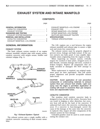
  • 1. INTAKE MANIFOLD EXHAUST PIPE MUFFLER CATALYTIC CONVERTER TAILPIPE EXHAUST MANIFOLD XJ EXHAUST SYSTEM AND INTAKE MANIFOLD 11 - 1 EXHAUST SYSTEM AND INTAKE MANIFOLD CONTENTS page page GENERAL INFORMATION EXHAUST MANIFOLD—4.0L ENGINE . . . . . . . . 8 CATALYTIC CONVERTER . . . . . . . . ......... 1 EXHAUST PIPE . . . . . . . . . . . . . . . . . . . . . . . . . 2 EXHAUST SYSTEM . . . . . . . . . . . . . ......... 1 INTAKE MANIFOLD—2.5L ENGINE . . . . . . . . . . 5 DIAGNOSIS AND TESTING INTAKE MANIFOLD—4.0L ENGINE . . . . . . . . . . 6 EXHAUST SYSTEM DIAGNOSIS . . . ......... 2 MUFFLER AND EXHAUST TAILPIPE . . . . . . . . . 4 REMOVAL AND INSTALLATION SPECIFICATIONS CATALYTIC CONVERTER . . . . . . . . ......... 3 TORQUE SPECIFICATIONS . . . . . . . ......... 8 EXHAUST MANIFOLD—2.5L ENGINE ........ 8 GENERAL INFORMATION The 4.0L engines use a seal between the engine exhaust manifold and exhaust pipe to assure a tight EXHAUST SYSTEM seal and strain free connections. The basic exhaust system consists of an engine The exhaust system must be properly aligned to exhaust manifold, exhaust pipe with oxygen sensor, prevent stress, leakage and body contact. If the sys- catalytic converter with oxygen sensor, muffler and tem contacts any body panel, it may amplify objec- exhaust tailpipe (Fig. 1). tionable noises originating from the engine or body. When inspecting an exhaust system, critically inspect for cracked or loose joints, stripped screw or bolt threads, corrosion damage and worn, cracked or broken hangers. Replace all components that are badly corroded or damaged. DO NOT attempt to repair. When replacement is required, use original equip- ment parts (or their equivalent). This will assure proper alignment and provide acceptable exhaust noise levels. CAUTION: Avoid application of rust prevention compounds or undercoating materials to exhaust system floor pan exhaust heat shields. Light over spray near the edges is permitted. Application of coating will result in excessive floor pan tempera- tures and objectionable fumes. CATALYTIC CONVERTER The stainless steel catalytic converter body is designed to last the life of the vehicle. Excessive heat can result in bulging or other distortion, but exces- sive heat will not be the fault of the converter. If unburned fuel enters the converter, overheating may occur. If a converter is heat-damaged, correct the cause of the damage at the same time the converter is replaced. Also, inspect all other components of the exhaust system for heat damage. Fig. 1 Exhaust System—Typical Unleaded gasoline must be used to avoid contami- The exhaust system uses a single muffler with a nating the catalyst core. catalytic converter consisting of dual ceramic mono- liths.
  • 2. 11 - 2 EXHAUST SYSTEM AND INTAKE MANIFOLD XJ DIAGNOSIS AND TESTING EXHAUST SYSTEM DIAGNOSIS CAUTION: When servicing and replacing exhaust components, disconnect the oxygen sensor connectors. Allowing the exhaust to hang by the oxygen sensor wires will damage the harness and/or sensor. CONDITION POSSIBLE CAUSE CORRECTION EXCESSIVE EXHAUST NOISE OR 1. Leaks at pipe joints. 1. Tighten clamps/bolts at leaking LEAKING EXHAUST GASES joints. 2. Rusted or blown out muffler. 2. Replace muffler. Inspect exhaust system. 3. Broken or rusted out exhaust pipe. 3. Replace exhaust pipe. 4. Exhaust pipe leaking at manifold 4. Tighten/replace flange attaching flange. nuts/bolts. 5. Exhaust manifold cracked or 5. Replace exhaust manifold. broken. 6. Leak between exhaust manifold 6. Tighten exhaust manifold to and cylinder head. cylinder head bolts. 7. Catalytic converter rusted or blown 7. Replace catalytic converter assy. out. 8. Restriction in exhaust system. 8. Remove restriction, if possible. Replace restricted part if necessary. REMOVAL AND INSTALLATION apply heat until the metal becomes cherry red. Dis- connect the exhaust pipe from the catalytic converter EXHAUST PIPE (Fig. 2). Remove the exhaust pipe. WARNING: IF TORCHES ARE USED WHEN WORK- INSTALLATION ING ON THE EXHAUST SYSTEM, DO NOT ALLOW (1) Assemble exhaust pipe to manifold and cata- THE FLAME NEAR THE FUEL LINES. lytic converter loosely to permit proper alignment of all parts. (2) Use a new clamp and tighten the nuts to 61 CAUTION: When servicing exhaust system compo- N·m (45 ft. lbs.) torque. nents, disconnect the oxygen sensor connector. (3) Connect the exhaust pipe to the engine exhaust Allowing the exhaust system to hang by the oxygen manifold. Install a new seal between the exhaust sensor harness will damage the wiring and/or sen- manifold and the exhaust pipe (4.0L engine only). sor. Tighten the nuts to 31 N·m (23 ft. lbs.) torque (Fig. 2). (4) Install the rear crossmember. Install and REMOVAL tighten the four (4) crossmember to rear mount nuts (1) Raise and support the vehicle. to 22 N·m (16 ft. lbs.) Install and tighten the cross- (2) Saturate the bolts and nuts with heat valve member to sill bolts to 42 N·m (31 ft. lbs.) torque. lubricant (Fig. 2). Allow 5 minutes for penetration. Remove the support from the transmission. (3) Disconnect the oxygen sensor connector (Fig. (5) Coat the oxygen sensor with anti-seize com- 3). pound. Install the sensor and tighten the nut to 27 (4) Disconnect the exhaust pipe from the engine N·m (20 ft. lbs.) torque. exhaust manifold. Discard the seal (4.0L engine, (6) Lower the vehicle. only). (7) Start the engine and inspect for exhaust leaks (5) Support the transmission and remove the rear and exhaust system contact with the body panels. crossmember. Adjust the alignment, if needed. (6) Remove the clamp nuts and clamp (Fig. 2). To remove the exhaust pipe from the catalytic converter,
  • 3. SEAL (4.0L) MANIFOLD NUT UPSTREAM SENSOR GEN OXY- DOWNSTREAM OXY- GEN SENSOR EXHAUST PIPE TRANSMISSION TRANSMISSION SUPPORT BRACKET CLAMP CATALYTIC CONVERTERCATALYTIC CONVERTER SUPPORT BRACKET EXHAUST PIPE CLAMPS MUFFLER XJ EXHAUST SYSTEM AND INTAKE MANIFOLD 11 - 3 REMOVAL AND INSTALLATION (Continued) Fig. 2 Exhaust Pipe Removal—2.5L/4.0L REMOVAL (1) Raise and support the vehicle. (2) Remove the clamps from the catalytic converter and muffler connection (Fig. 4). (3) Disconnect and remove the oxygen sensor from the catalytic converter. (4) Heat the catalytic converter and muffler con- nection with an oxyacetylene torch until the metal becomes cherry red. (5) While the metal is still cherry red, twist the muffler assembly back and forth to separate it from the catalytic converter. (6) Disconnect the exhaust pipe from the catalytic converter (Fig. 4). If needed, heat up the pipes to sep- arate. Fig. 3 Oxygen Sensor Location CATALYTIC CONVERTER WARNING: IF TORCHES ARE USED WHEN WORK- ING ON THE EXHAUST SYSTEM, DO NOT ALLOW THE FLAME NEAR THE FUEL LINES. CAUTION: When servicing exhaust system compo- nents, disconnect the oxygen sensor connector. Allowing the exhaust system to hang by the oxygen sensor harness will damage the wiring and/or sen- sor. Fig. 4 Catalytic Converter to Muffler and Exhaust Pipe Connection
  • 4. FRONT MUFFLER TAILPIPE HANGER CATALYTIC CONVERTER INSULATOR CLAMP TAILPIPE MUFFLER 11 - 4 EXHAUST SYSTEM AND INTAKE MANIFOLD XJ REMOVAL AND INSTALLATION (Continued) INSTALLATION (1) Connect the catalytic converter to the exhaust pipe and the muffler/tailpipe assy. (Fig. 4). Use a new clamp and tighten the nuts to 61 N·m (45 ft. lbs.) torque. (2) Install the muffler onto the catalytic converter until the alignment tab is inserted into the align- ment slot. (3) Install a new clamp at the muffler and cata- lytic converter connection (Fig. 4). Tighten the clamp nut to 61 N·m (45 ft. lbs.) torque. (4) Coat the oxygen sensor with anti-seize com- pound. Install the sensor and tighten the nut to 27 N·m (20 ft. lbs.) torque. (5) Lower the vehicle. (6) Start the engine and inspect for exhaust leaks and exhaust system contact with the body panels. Adjust the alignment, if needed. MUFFLER AND EXHAUST TAILPIPE All original equipment exhaust systems are manu- factured with the exhaust tailpipe welded to the muf- fler. Service replacement mufflers and exhaust Fig. 5 Front Exhaust Tailpipe Hanger tailpipes are either clamped together or welded together. WARNING: IF TORCHES ARE USED WHEN WORK- ING ON THE EXHAUST SYSTEM, DO NOT ALLOW THE FLAME NEAR THE FUEL LINE. CAUTION: When servicing exhaust system compo- nents, disconnect the oxygen sensor connector. Allowing the exhaust system to hang by the oxygen sensor harness will damage the wiring and/or sen- sor. REMOVAL (1) Raise and support the vehicle. (2) Disconnect front tailpipe hanger from the insu- Fig. 6 Catalytic Converter to Muffler Connection lator (Fig. 5). (3) Remove the front exhaust clamp from the cat- close to the muffler. Collapse the part remaining in alytic converter and muffler connection (Fig. 6). the muffler and remove. (4) Heat the catalytic converter-to-muffler connec- • To remove a service exhaust tailpipe/muffler tion with an oxyacetylene torch until the metal combination, apply heat until the metal becomes becomes cherry red. cherry red. Remove the exhaust tailpipe/muffler (5) While the metal is still cherry red, remove the clamp and twist the exhaust tailpipe out of the muf- exhaust muffler/tailpipe assembly from the catalytic fler. converter. (8) If the tailpipe is also to be replaced (6) Slide the muffler/tailpipe assy. rearward and INSTALLATION out of the rear exhaust tailpipe mounting bracket (1) Install the muffler onto the catalytic converter. (Fig. 7). Install the clamp and tighten the nuts finger tight. (7) Remove the muffler from the exhaust tailpipe: (2) Install the exhaust tailpipe into the rear of the • To remove an original equipment exhaust muf- muffler. fler/tailpipe combination, cut the exhaust tailpipe (3) Install the exhaust tailpipe/muffler assembly on the rear exhaust tailpipe mounting bracket. Make
  • 5. MUFFLER/TAILPIPE ASSEM- TAILPIPE BRACKET BLY ING MOUNT- XJ EXHAUST SYSTEM AND INTAKE MANIFOLD 11 - 5 REMOVAL AND INSTALLATION (Continued) stallation (refer to Group 14, Fuel System - Quick Connect Fittings). (7) Disconnect the accelerator cable, the cruise control cable (if equipped), and the transmission line pressure cable (if equipped) from the throttle body and remove them from the cable bracket. CAUTION: When disconnecting the cruise control connector at the throttle body, DO NOT pry the con- nector off with pliers or screwdriver. Use finger pressure only. Prying the connector off could break it. (8) Disconnect the electrical connectors. Pull the harnesses away from the manifold and secure them so they do not interfere with the manifold removal and installation process. • The throttle position sensor. • The idle air control motor. • The coolant temperature sensor at the thermo- stat. • The manifold air temperature sensor at the Fig. 7 Rear Exhaust Tailpipe Mounting Bracket intake manifold. • The fuel injectors. sure that the exhaust tailpipe has sufficient clear- • The oxygen sensor. ance from the floor pan. (9) Disconnect the crankcase ventilation (CCV) (4) Install front tailpipe hanger into the insulator vacuum hose and manifold absolute pressure (MAP) (Fig. 5). sensor vacuum hose connector at the intake mani- (5) Align the muffler and tighten the nuts on the fold. muffler-to-catalytic converter clamp to 61 N·m (45 ft. (10) Disconnect vacuum hose from vacuum port on lbs.) torque (Fig. 6). the intake manifold. (6) Align the tailpipe and install a new clamp at (11) Disconnect CCV hose at the cylinder head the muffler to tailpipe connection. cover (Fig. 8). (7) Tighten the muffler to tailpipe clamp to 61 N·m (12) Remove the molded vacuum harness. (45 ft. lbs.) (13) Disconnect the vacuum brake booster hose at (8) Lower the vehicle. the intake manifold. (9) Start the engine and inspect for exhaust leaks (14) Remove bolts 2 through 5 securing the intake and exhaust system contact with the body panels. manifold to the cylinder head (Fig. 11). Slightly Adjust the alignment, if needed. loosen bolt No.1 and nuts 6 and 7. (15) Remove the intake manifold and gaskets. INTAKE MANIFOLD—2.5L ENGINE Drain the coolant from the manifold. REMOVAL INSTALLATION (1) Disconnect the battery negative cable. (1) Clean the intake manifold and cylinder head (2) Remove the air inlet hose from the throttle mating surfaces. DO NOT allow foreign material body and air cleaner. to enter either the intake manifold or the ports (3) Loosen the accessory drive belt tension and in the cylinder head. remove the belt from the power steering pump (refer (2) Install the new intake manifold gasket over the to Group 07, Cooling Systems for proper procedures). locating dowels. (4) Remove the power steering pump and brackets (3) Position the manifold in place and finger from the water pump and intake manifold. Secure tighten the mounting bolts. power steering pump and bracket out of the way. (4) Tighten the fasteners in sequence and to the (5) Perform fuel system pressure release procedure specified torque (Fig. 11). (refer to Group 14, Fuel System for correct proce- • Fastener No.1—Tighten to 41 N·m (30 ft. lbs.) dure). torque. (6) Disconnect fuel supply tube from the fuel rail. • Fasteners Nos.2 through 7—Tighten to 31 N·m Some fuel lines require a special tool for removal/in- (23 ft. lbs.) torque.
  • 6. FIXED AIR ORIFICE INLET TING FITTING AIR COVER FILTER FIT- 11 - 6 EXHAUST SYSTEM AND INTAKE MANIFOLD XJ REMOVAL AND INSTALLATION (Continued) (13) Install and tension the accessory drive belt. Refer to Group 7, Cooling System for the proper pro- cedure. CAUTION: Ensure that the accessory drive belt is routed correctly. Failure to do so can cause the water pump to turn in the opposite direction result- ing in engine overheating. Refer to Group 7, Cool- ing System for the proper procedure. (14) Connect the air inlet hose to the throttle body and the air cleaner. (15) Connect the battery negative cable. (16) Start the engine and check for leaks. INTAKE MANIFOLD—4.0L ENGINE The intake and engine exhaust manifolds on the 4.0L engine must be removed and installed together. The two manifolds use a common gasket at the cyl- inder head. REMOVAL (1) Disconnect the battery negative cable. Fig. 8 Crankcase Ventilation (CCV) Hose—2.5L (2) Remove air cleaner inlet hose from throttle Engine plate assembly. (5) Connect fuel supply tube to the fuel rail inlet. (3) Remove the air cleaner assembly. Push tube until a “click” is heard. Before connect- (4) Remove the throttle cable, cruise control cable ing the fuel line to the fuel rail replace the (if equipped) and the transmission line pressure O-rings at the quick-connect fuel line coupling. cable. (6) Pull out on the fuel supply tube to ensure that (5) Disconnect the crankcase ventilation (CCV) it is locked in place. vacuum hose and manifold absolute pressure (MAP) (7) Connect the molded vacuum hoses to the vac- sensor vacuum hose connector at the intake mani- uum port on the intake manifold and the cylinder fold. head cover. (6) Disconnect vacuum hose from vacuum port on (8) Connect the electrical connectors. the intake manifold. • The throttle position sensor. (7) Disconnect CCV hose at the cylinder head • The idle air control motor. cover (Fig. 9). • The coolant temperature sensor at the thermo- (8) Perform fuel system pressure release procedure stat housing. (refer to Group 14, Fuel System for correct proce- • The fuel injectors. dure). • The air manifold temperature sensor. (9) Remove fuel supply line latch clip at injector • The oxygen sensor. rail. (9) Connect the CCV vacuum hose and MAP sen- (10) Disconnect fuel supply tube from the fuel rail. sor vacuum hose connectors to the throttle body. Some fuel lines require a special tool for removal/in- (10) Install the power steering pump and bracket stallation (refer to Group 14, Fuel System - Quick assembly to the water pump and intake manifold. Connect Fittings). Hand start the three (3) tensioner bracket to p/s (11) Disconnect all electrical connectors on the pump to intake manifold bolts and the two (2) ten- intake manifold. sioner bracket to water pump bolts. • The throttle position sensor. (11) Tighten the power steering pump bolts to 28 • The idle air control motor. N·m (21 ft. lbs.) Tighten the tensioner bracket to • The coolant temperature sensor at the thermo- water pump bolts to 28 N·m (21 ft. lbs.). stat. (12) Connect the accelerator cable, cruise control • The manifold air temperature sensor at the cable (if equipped), and the transmission line pres- intake manifold. sure cable (if equipped) to the hold-down bracket and • The fuel injectors. the throttle lever. • The oxygen sensor.
  • 7. AIR INLET TING FIT- FWDIXED F ORIFICE FITTING AIR COVER FILTER CYLINDER HEAD DOWEL EXHAUST INTAKE MANI- MANI- FOLD FOLD CYLINDER HEADDOWEL XJ EXHAUST SYSTEM AND INTAKE MANIFOLD 11 - 7 REMOVAL AND INSTALLATION (Continued) (8) Tighten the fasteners in sequence and to the specified torque (Fig. 10). • Fasteners Nos.1 through 5—Tighten to 33 N·m (24 ft. lbs.) torque. • Fasteners Nos.6 and 7—Tighten to 31 N·m (23 ft. lbs.) torque. • Fasteners Nos.8 through 11—Tighten to 33 N·m (24 ft. lbs.) torque. Fig. 9 Crankcase Ventilation (CCV) Hose —4.0L Engine Fig. 10 Intake/Engine Exhaust Manifold Installation (12) Loosen the accessory drive belt tension and (4.0L Engine) remove the belt from the power steering pump (refer to Group 07, Cooling Systems for proper procedures). (9) Install the power steering pump and bracket to (13) Remove the power steering pump and bracket the intake manifold and water pump. Tighten the from the intake manifold and water pump and set belt to specification (Refer to Group 7, Cooling Sys- aside. tem for the proper procedures). (14) Raise the vehicle. (10) Connect fuel supply tube to the fuel rail inlet. (15) Disconnect the exhaust pipe from the engine Push tube until a “click” is heard. Before connect- exhaust manifold. Discard the seal. ing the fuel line to the fuel rail replace the (16) Lower the vehicle. O-rings at the quick-connect fuel line coupling. (17) Remove the intake manifold and engine (11) Pull out on the fuel supply tube to ensure that exhaust manifold. it is locked in place. (12) Replace latch clip. INSTALLATION (13) Connect all electrical connections on the (1) Clean the mating surfaces of the cylinder head intake manifold. and the manifold if the original manifold is to be re- (14) Connect the vacuum connector on the intake installed. manifold and install it in the bracket. (2) If the manifold is being replaced, ensure all the (15) Install throttle cable, cruise control cable (if sensors, fittings, etc. are transferred to the replace- equipped). ment manifold. (16) Install the transmission line pressure cable (if (3) Install a new exhaust/intake manifold gasket equipped). Refer to Group 21, Transmission for the over the alignment dowels on the cylinder head. adjustment procedures. (4) Position the engine exhaust manifold to the (17) Install air cleaner assembly. cylinder head. Install fastener No.3 and finger (18) Connect air inlet hose to the throttle plate tighten at this time (Fig. 10). assembly. (5) Install intake manifold on the cylinder head (19) Raise the vehicle on a side mounted hoist. dowels. (20) Using a new seal, connect the exhaust pipe to (6) Install washers and fasteners Nos.1, 2, 4, 5, 8, the engine exhaust manifold. Tighten the bolts to 31 9, 10 and 11 (Fig. 10). N·m (23 ft. lbs.) torque. (7) Install washers and fasteners Nos.6 and 7 (Fig. (21) Lower the vehicle. 10). (22) Connect the battery negative cable. (23) Start the engine and check for leaks.
  • 8. SPACER EXHAUST MANI- FOLD CYLINDER HEAD DOWELS INTAKE MANI- FOLDSPACER 11 - 8 EXHAUST SYSTEM AND INTAKE MANIFOLD XJ REMOVAL AND INSTALLATION (Continued) EXHAUST MANIFOLD—2.5L ENGINE (8) Tighten nuts 6 and 7 to 31 N·m (23 ft. lbs.) torque (Fig. 11). REMOVAL (9) Install all components to the intake manifold. (1) Disconnect the battery negative cable. (10) Raise the vehicle. (2) Raise the vehicle. (11) Connect the exhaust pipe to the engine (3) Disconnect the exhaust pipe from the engine exhaust manifold. Tighten the bolts to 31 N·m (23 ft. exhaust manifold. lbs.) torque. (4) Lower the vehicle. (12) Lower the vehicle. (5) Remove intake manifold (refer to procedure in (13) Connect the battery negative cable. this section) (14) Start the engine and check for leaks. (6) Remove fasteners 2 through 5 and remove the intake manifold (Fig. 11). EXHAUST MANIFOLD—4.0L ENGINE (7) Remove fasteners 1, 6 and 7 and remove the The intake and engine exhaust manifolds on the engine exhaust manifold (Fig. 11). 4.0L engine must be removed and installed together. The manifolds use a common gasket at the cylinder head. Refer to Intake Manifold—4.0L Engine in this sec- tion for the proper removal and installation proce- dures. SPECIFICATIONS TORQUE SPECIFICATIONS Description Torque Catalytic Converter/Exhaust Pipe Exhaust Clamp Nut . . . . . . . . . . 61 N·m (45 ft. lbs.) Crossmember to Sill Bolts . . . . . . . . . . . . . . . . . . . . . . 42 N·m (31 ft. lbs.) Fig. 11 Intake/Exhaust Manifold Removal/ Crossmember to Transmission Mount Installation—2.5L Engine Nuts . . . . . . . . . . . . . . . . . . . . . . 22 N·m (16 ft. lbs.) Exhaust Pipe to Manifold INSTALLATION Nuts . . . . . . . . . . . . . . . . . . . . . . 31 N·m (23 ft. lbs.) (1) Clean the intake and engine exhaust manifolds Exhaust Manifold–2.5L Engine and cylinder head mating surfaces. DO NOT allow Bolt #1 . . . . . . . . . . . . . . . . . . . . 41 N·m (30 ft. lbs.) foreign material to enter either the intake man- Exhaust Manifold–2.5L Engine ifold or the ports in the cylinder head. Bolts #2–5 . . . . . . . . . . . . . . . . . . 31 N·m (23 ft. lbs.) (2) Install a new intake manifold gasket over the alignment dowels on the cylinder head. Exhaust Manifold–4.0L Engine (3) Install the engine exhaust manifold assembly. Nuts/Bolts #1–5 & #8–11 . . . . . . 33 N·m (24 ft. lbs.) Exhaust manifold must be centrally located Exhaust Manifold–2.5L Engine over the end studs and spacer (Fig. 11). Nuts #6&7 . . . . . . . . . . . . . . . . . 31 N·m (23 ft. lbs.) (4) Tighten bolt No.1 to 41 N·m (30 ft. lbs.) torque Exhaust Manifold–4.0L Engine (Fig. 11). Nuts #6&7 . . . . . . . . . . . . . . . . . 31 N·m (23 ft. lbs.) (5) Install the intake manifold on the cylinder Intake Manifold–2.5L Engine head dowels (Fig. 11). Bolt #1 . . . . . . . . . . . . . . . . . . . . 41 N·m (30 ft. lbs.) (6) Install bolts 2 through 5 (Fig. 11). Tighten Intake Manifold–2.5L Engine these bolts to 31 N·m (23 ft. lbs.) torque. Bolt #2–5 . . . . . . . . . . . . . . . . . . 31 N·m (23 ft. lbs.) (7) Install new engine exhaust manifold spacers Muffler to Catalytic Converter over the engine exhaust manifold mounting studs in Exhaust Clamp Nut . . . . . . . . . . 61 N·m (45 ft. lbs.) the cylinder head (Fig. 11). Oxygen Sensors Nut . . . . . . . . . . . . . . . . . . . . . . . 27 N·m (20 ft. lbs.) Rear Tail Pipe Hanger Nuts . . . . . . . . . . . . . . . . . . . . . . 54 N·m (40 ft. lbs.)
  • 9. XJ EXHAUST SYSTEM AND INTAKE MANIFOLD 11 - 1 EXHAUST SYSTEM AND INTAKE MANIFOLD CONTENTS page page GENERAL INFORMATION EXHAUST PIPE . . . . . . . . . . . . . . . .......... 1 EXHAUST HEAT SHIELDS . . . . . . . . . . . . . . . . . 1 INTAKE MANIFOLD . . . . . . . . . . . . .......... 3 EXHAUST SYSTEM . . . . . . . . . . . . . . . . . . . . . . 1 MUFFLER AND EXHAUST TAILPIPE ......... 2 REMOVAL AND INSTALLATION SPECIFICATIONS ENGINE EXHAUST MANIFOLD AND TORQUE SPECIFICATIONS . . . . . . .......... 4 TURBOCHARGER . . . . . . . . . . . . . . . . . . . . . 2 GENERAL INFORMATION EXHAUST SYSTEM The basic exhaust system consists of an engine exhaust manifold, exhaust pipe, exhaust heat shield(s), muffler and exhaust tailpipe The exhaust system uses a single muffler. The exhaust system must be properly aligned to prevent stress, leakage and body contact. If the sys- tem contacts any body panel, it may amplify objec- tionable noises originating from the engine or body. When inspecting an exhaust system, critically inspect for cracked or loose joints, stripped screw or bolt threads, corrosion damage and worn, cracked or broken hangers. Replace all components that are badly corroded or damaged. DO NOT attempt to repair. Fig. 1 Heat Shields When replacement is required, use original equip- REMOVAL AND INSTALLATION ment parts (or equivalent). This will assure proper alignment and provide acceptable exhaust noise lev- EXHAUST PIPE els. WARNING: IF TORCHES ARE USED WHEN WORK- CAUTION: Avoid application of rust prevention ING ON THE EXHAUST SYSTEM, DO NOT ALLOW compounds or undercoating materials to exhaust THE FLAME NEAR THE FUEL LINES. system floor pan exhaust heat shields. Light over- spray near the edges is permitted. Application of coating will result in excessive floor pan tempera- REMOVAL tures and objectionable fumes. (1) Raise and support the vehicle. (2) Saturate the bolts and nuts at turbo down pipe to exhaust pipe with heat valve lubricant. Allow 5 EXHAUST HEAT SHIELDS minutes for penetration.. Exhaust heat shields are needed to protect both (3) Disconnect bolts from exhaust pipe to turbo the vehicle and the environment from the high tem- down pipe (Fig. 2). peratures (Fig. 1). (4) Remove the clamp nuts at muffler (Fig. 3). To DO NOT allow the engine to operate at fast idle for remove the exhaust pipe from the muffler, apply heat extended periods (over 5 minutes). This condition until the metal becomes cherry red. Disconnect the may result in excessive temperatures in the exhaust exhaust pipe from the muffler. Remove the exhaust system and on the floor pan. pipe. INSTALLATION (1) Assemble exhaust pipe to muffler, loosely to permit proper alignment of all parts.
  • 10. 11 - 2 EXHAUST SYSTEM AND INTAKE MANIFOLD XJ REMOVAL AND INSTALLATION (Continued) REMOVAL (1) Raise and support the vehicle. (2) Remove the front muffler clamp from the exhaust pipe and muffler connection. (3) Remove the rear exhaust tailpipe hanger clamp and remove the exhaust tailpipe from the front exhaust tailpipe hanger. (4) Remove the exhaust tailpipe assembly from the muffler. INSTALLATION (1) Install the muffler onto the exhaust pipe. Install the clamp and tighten the nuts finger tight. (2) Install the exhaust tailpipe into the rear of the muffler. (3) Install the exhaust tailpipe/muffler assembly Fig. 2 Exhaust Down Pipe to Front Exhaust Pipe on the rear exhaust tailpipe hanger. Make sure that the exhaust tailpipe has sufficient clearance from the floor pan. (4) Install the remaining clamps and the front exhaust tailpipe hanger. (5) Tighten the nuts on the muffler-to-exhaust pipe clamp to 43 N·m torque. (6) Tighten the nuts on the muffler-to-exhaust pipe clamp to 43 N·m torque. (7) Lower the vehicle. (8) Start the engine and inspect for exhaust leaks and exhaust system contact with the body panels. Adjust the alignment, if needed. ENGINE EXHAUST MANIFOLD AND TURBOCHARGER REMOVAL Fig. 3 Front Pipe to Muffler (1) Disconnect the battery negative cable. (2) Connect the exhaust pipe to the turbo down (2) Remove air cleaner hoses from turbocharger. pipe manifold. Tighten the bolts to 22.5 N·m torque. (3) Remove air cleaner assembly. (3) Use a new clamp and tighten the nuts to 43 (4) Remove charge air cooler hoses from turbo- N·m torque. charger and intake manifold. (4) Lower the vehicle. (5) Remove all components attached to the intake (5) Start the engine and inspect for exhaust leaks manifold. and exhaust system contact with the body panels. (6) Remove the EGR tube and EGR valve. Adjust the alignment, if needed. (7) Remove exhaust manifold heat shield. (8) Remove turbocharger oil feed line (Fig. 4). MUFFLER AND EXHAUST TAILPIPE (9) Remove exhaust down pipe from turbo. All original equipment exhaust systems are manu- (10) Raise the vehicle factured with the exhaust tailpipe welded to the muf- (11) Remove oil drain tube from turbocharger fler. Service replacement mufflers and exhaust (12) Lower the vehicle tailpipes are either clamped together or welded (13) Remove turbocharger and exhaust manifold as together. an assembly (Fig. 5). WARNING: IF TORCHES ARE USED WHEN WORK- CLEANING ING ON THE EXHAUST SYSTEM, DO NOT ALLOW Clean the exhaust manifold and cylinder head mat- THE FLAME NEAR THE FUEL LINES. ing surfaces.
  • 11. XJ EXHAUST SYSTEM AND INTAKE MANIFOLD 11 - 3 REMOVAL AND INSTALLATION (Continued) (4) Install exhaust down pipe to turbocharger, tighten bolts to 27 N·m. (5) Install exhaust heat shield, tighten bolts to 11 N·m. (6) Loose install EGR tube and EGR valve to intake manifold. (7) Install EGR valve, tighten bolts to 26 N·m. (8) Tighten EGR tube nut to 26 N·m. (9) Tighten EGR tube flange bolts to 26 N·m. (10) Connect all components to intake manifold. (11) Connect charge air cooler hoses to turbo- charger and intake manifold. (12) Install air cleaner assembly. (13) Connect air cleaner hose to turbocharger. (14) Raise the vehicle (15) Install turbocharger drain line. (16) Lower the vehicle (17) Connect the battery negative cable. (18) Start the engine and check for leaks. INTAKE MANIFOLD Fig. 4 Turbocharger Oil Feed Line REMOVAL (1) Remove exhaust manifold and turbocharger INSTALLATION assembly. (1) Install turbocharger to exhaust manifold (2) Remove water manifold. tighten nuts to 27 N·m. (3) Remove intake manifold. (2) Install assembly to engine, tighten nuts to 30 N·m. CLEANING Clean the intake manifold and cylinder head mat- ing surfaces. DO NOT allow foreign material to enter either the intake manifold or the ports in the cylinder head. INSTALLATION (1) Install the new intake manifold gasket. (2) Position the intake manifold in place and fin- ger tighten the mounting nuts. (3) Tighten the fasteners in sequence and to the specified torque 30 N·m. (4) Position the water manifold in place and finger tighten the mounting nuts. (5) Tighten the fasteners to the specified torque 12 N·m. (6) Install exhaust manifold and turbocharger Fig. 5 Exhaust Manifold and Turbocharger assembly. (7) Install charge air cooler hose to intake mani- (3) Install oil feed line to turbocharger, tighten nut fold. to 26 N·m. (8) Connect the battery negative cable. (9) Start engine and check for leaks.
  • 12. 11 - 4 EXHAUST SYSTEM AND INTAKE MANIFOLD XJ SPECIFICATIONS TORQUE SPECIFICATIONS Description Torque EGR Attaching Nuts . . . . . . . . . . . . . . . . . . . . . . . 19 N·m EGR Tube Nut . . . . . . . . . . . . . . . . . . . . . . . . . . . 34 N·m EGR Tube Flange Bolts . . . . . . . . . . . . . . . . . . . . . 26 N·m Exhaust Manifold Nuts . . . . . . . . . . . . . . . . . . . . . . . . . . . . . . . 30 N·m Exhaust Manifold Heat Shield Nuts . . . . . . . . . . . . . . . . . . . . . 11 N·m Exhaust Pipe Support Clamp Bolts . . . . . . . . . . . . . . . . . 22.5 N·m Exhaust Pipe Support Clamp Screw . . . . . . . . . . . . . . . . 22.5 N·m Intake Manifold Nuts . . . . . . . . . . . . . . . . . . . . . . . . . . . . . . . 30 N·m Muffler-to-Exhaust Pipe Clamp Nuts . . . . . . . . . . . . . . . . . . . . . . . . . 43 N·m Tail Pipe Clamp Hanger bolt . . . . . . . . . . . . . . . . . . . . . . . . 22.5 N·m Turbocharger-to-Exhaust manifold Nuts . . . . . . . . . . . . . . . . . . . . . . . . . . . . . . . 27 N·m Turbocharger Oil Feed Line . . . . . . . . . . . . . . . . . . . . . . . 27.4 N·m Turbocharger Down Pipe-to-Exhaust Pipe Bolts/Nuts . . . . . . . . . . . . . . . . . . . . . . . . . 22.5 N·m Turbocharger Down Pipe-to-Turbocharger Bolts . . . . . . . . . . . . . . . . . . . . . . . . . . . . . . . 27 N·m