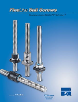
2. FineLine Ball Screws
FineLine Ball Screws were developed
by BS&A (previously known as Warner
Linear) in Wolfschlugen, Germany, and
have been sold in Europe since 1999.
The screws have been successfully de-
ployed in high-precision applications in
transporation, manufacturing, health, fit-
ness, robotics, plastics and packaging
industries. BS&A’s PSF Technology™
enables us to manufacture ball screws
with accuracy and performance in the
same class as precision ground screws,
yet without the extreme expense of
grinding processes.
Exclusive PSF Technology™
Precision Screw Forming (PSF) Tech-
nology is based on a proprietary pro-
cess of precision roll forming. Through
years of research, development and
partnering with steel suppliers and
equipment manufacturers we have de-
• Quiet operation: High degree of ac-
curacy and exceptional surface finish
assure quiet operation.
• Consistent running torque: Precise
screw cylindricality and ball-track
roundness (max. deviation of 3 to
6 µm), both of which are necessary for
consistent running torque in critical
applications such as machine tool
slides.
• Preloads: Can be supplied with cus-
tomer-specified preloads from zero to
13% of the dynamic load rating.
• Flanges and Finish Machining:
Available with flanged and non-
flanged nut assemblies and machined
standard end journals.
veloped a CNC-based rolling process.
At the heart of the process is the ability
to dynamically control both roller dies
as well as other variables in the manu-
facturing process. The end result of this
German-engineered process is the pro-
duction of highly cost effective rolled
product with capabilities equaling those
normally attributed only to ground screws.
Features and Benefits
• Accuracy: Available in ISO accuracy
grades P3 and P5 (permissible travel
variation of 12 µm/300 mm and 23µm/
300 mm, respectively), as well as in
transport grades T5 and T7.
• Smooth operation: Made of high car-
bon alloy steel that we induction
harden, stress relieve, and then pol-
ish to insure excellent operating
smoothness.
The high precision alternative to costly ground ball screws.
ELECTROMATE
Toll Free Phone (877) SERVO98
Toll Free Fax (877) SERV099
www.electromate.com
sales@electromate.com
Sold & Serviced By:
5. BS&A FineLine Ball Screws 3Technical Overview
TechnicalOverview&
FunctionalHighlights
Precision Screw Forming Technology™
BS&A’s patented, German-engineered
Precision Screw Forming (PSF) Tech-
nology has created a higher perform-
ing ball screw, combining outstanding
precision—traditionally only associated
with ground screws—with the manu-
facturing efficiency of rolled processes.
The result is an affordable ball screw
with highest precision and outstanding
performance.
BS&A FineLine ball screws are equal
in accuracy and performance to ground
screws of the same accuracy class,
but with harder grain structures (see
inset), lower costs, and short manu-
facturing times (provides significantly
reduced lead times for our customers).
PSF Technology consistently produces
screws with accuracies ranging up to
P3 class tolerances (ISO 3408 stan-
dard), a dramatic improvement over
existing rolled manufacturing processes
that typically produce only transport-
grade screws (up to class 7). PSF
Technology brings affordable precision
to a range of new applications.
What is PSF Technology?
Precision Screw Forming is an exact-
ing manufacturing process that results
in a superior ball screw. First, high car-
bon alloy steel blanks are processed
into screws of length up to four meters
(over 13 feet) in a special CNC-con-
trolled, dual-movable-die, cold-forming
machine. Second, the screw forms are
induction-hardened and stress-relieved.
Next, the screws are polished to pro-
duce a ball track with surface tough-
ness superior to a ground screw. Fi-
nally, the ball screw is mated with its
nut (loaded to user specifications), in-
spected and tested to customer re-
quirements. The result is a high preci-
sion, high quality ball screw/nut assem-
bly.
What are the Benefits of PSF
Technology?
Here are just some of the benefits as-
sociated with ball screws made using
PSF Technology:
1. FineLine ball screws offer low cost,
high precision performance in ap-
plications typically requiring ground
screws. FineLine also offers the op-
portunity for greater precision in ap-
plications where ground screws have
been too expensive to consider.
2. Responsive manufacturing & delivery
times: PSF Technology is a fast, non-
batch manufacturing process, with
delivery times of less than two weeks,
compared with the typical 2-3 month
lead times of ground ball screws.
3. No hard spots: The PSF process
does not expose hard spots
(“corns”) as grinding does. Hard
spots can mar ball surfaces and
shorten screw life by up to 20%.
4. Quieter running: The superior sur-
face finish of FineLine ball screws
gives smooth operations with mini-
mal noise.
FineLine Ball Screws – Better Grain Structures
In addition to equaling some of the top accuracy classes of ground screws,
our FineLine Ball Screws offer a distinct advantage over ground screws in
the screw’s arch. Screw rolling displaces grains, producing arch-shaped
grain structures, while grinding removes material and leaves asperities
exposed in the grain structure. FineLine rolled screws thus have increased
rust resistance, and a stronger, arched grain structure that induces hard-
ness under the surface of the screw.
FineLine Ball Screws with
PSF Technology
Arched grain provides in-
creased strength, hardness and
durability, resulting in reduced
friction and increased life.
Typical Ground Ball Screw
Grinding the screw reduces the
integrity of the steel and leaves
exposed asperities in the grain
structure, which can reduce
efficiency and useful life.
Micrograph shows
smooth, arched grain
structure of a screw
manufactured using
PSF Technology.
Profile of a
rolled PSF
Technology
screw
Micrograph shows grain
structure of a ground
screw.
Profile of a
ground
screw
ELECTROMATE
Toll Free Phone (877) SERVO98
Toll Free Fax (877) SERV099
www.electromate.com
sales@electromate.com
Sold & Serviced By:
7. BS&A FineLine Ball Screws 5Technical Overview
TechnicalOverview&
FunctionalHighlights
Preload Classes
Clearance Grade (Type Z2)
(No Preload)
Preload (Type Z1)
(Lightly preloaded)
Precise Preload (Type Z0)
(Precisely preloaded to
customer specifications)
Ph Ph+ Ph Ph
F
applied
No Preload
Ball bearings are undersized, thereby
creating clearance between the nut
and screw.
Preloaded
Oversized balls slightly larger than
the ball groove space are used to
provide four points of contact.
Precise Preload
The lead is offset by an amount, ∆Ph,
to preload with two points of contact
around the balls as shown.
FineLine Ball Screws are available in three preload classes: Clearance Grade (no
preload), Preload (lightly preloaded with four points of contact) and Precise Preload
(preloaded with two points of contact to exact customer specifications).
• Offers zero backlash between screw
and nut.
• The preload is approximately 5% of
dynamic load capacity.
• Typically used for positioning appli-
cations where repeatability is critical.
(Available with FK, FH & ZG style nuts.)
• Offers zero backlash between screw
and nut.
• The preload is approximately 10% of
dynamic load capacity, but can range
from 2% to 13% as specified by cus-
tomers. Drag torque is controlled
within a designated range.
• Typically used for positioning appli-
cations where repeatability and high
stiffness are required (high stiffness
allows for high load carrying with
minimum deflection).
(Available only with FL nut.)
• Axial play is present between screw
and nut, which negatively affects re-
peatability.
• Introduces no additional drag torque.
• Lead accuracy is unaffected, repeat-
ability is approximately equal to back-
lash amount. (Typical maximum
backlash is .09 to .18 mm, depending
on size.)
• Typically used for transport applica-
tions or vertical applications where
low drag is desirable.
(Available with FK, FH & ZG style nuts.)
ELECTROMATE
Toll Free Phone (877) SERVO98
Toll Free Fax (877) SERV099
www.electromate.com
sales@electromate.com
Sold & Serviced By:
23. BS&A FineLine Ball Screws 21Engineering Reference
EngineeringReference
Efficiency & Torque
Ta
FF
Te
F
The ball screw assembly’s performance
in converting between linear motion
and rotational torque is its efficiency,
η. Efficiency depends primarily on geo-
metrical data, though various operat-
ing influences can swing actual effi-
ciency by ±5% from the calculated. As
such, to account for operational influ-
ences such as speed, temperature, lu-
The theoretical
efficiency (η),
when converting
torque into
linear motion is:
The theoretical
efficiency (η′ ),
when converting
linear motion into
torque is:
Ta
FF
Te
F
When converting
torque into linear
motion, the necessary
drive torque is:
When converting linear
motion into torque, the
resulting output torque
is:
bricant, etc., approximately 5% of the
theoretical efficiency should be de-
ducted.
Furthermore, if the ratio of load (F) to
dynamic load rating (Cam) is below 0.5,
then an additional reduction in relation
to the load factor is to be applied (see
table below for fL).
The efficiency calculated on this basis
applies for the ball screw including lu-
brication but without considering wip-
ers or shaft support.
If an improvement in efficiency is re-
quired, please contact our engineering
department.
For approximate torque based on 90% efficiency:
T 0.177 F Pa h0= × ×
ρ" = friction angle
(0.23° for P-class
tolerances, 0.34° for
T-class tolerances)
ϕ = lead angle
Ph0, d0 = lead & diameter
(see product specifications)
F = axial load
Cam = dynamic load rating
Ta = drive torque
Te = output torque
fL = adjusted to load factor
η, η′ = theoretical efficiency
Load Adjustment Factors
Parameters:
T .143 F Pe h0= × ×
Efficiency: Rotary to Linear Efficiency: Linear to Rotary
Torque: Rotary to Linear Torque: Linear to Rotary
Practical Efficiency:
Example
Parameters:
40 x 10 mm screw, P3 class
F = 10 kN
Cam = 53.9 kN
Rotary to Linear Application
The lead angle, ϕ, is found:
The loading ratio is small, so a load
adjustment factor is required:
P3 precision indicates friction angle
of ρ"=0.23°
Thus, the theoretical efficiency is:
F
C ma
f(rotcafdaolottnemtsujdA L
)
5.0 00.1
4.0 99.0
3.0 89.0
2.0 79.0
1.0 69.0
Applying the load adjustment factor
and 5% reduction gives practical
efficiency of:
Torque required to drive the load is
given by:
T
T
a
a
=
×
× ×
=
10 000 010
2 88
18 1
, .
.
.
[N] [m]
[Nm]
π
η
ϕ
ϕ ρ π
=
+( )
tan
tan "
with tan
P
d
h0
0
ϕ =
×
η
ϕ ρ
ϕ
ϕ
π
′ =
−( )
=
×
tan "
tan
with tan
P
d
h0
0
η ηp Lf= × ×.95
T
F P
2a
h0
=
×
× ×π ηp
T
F P
2
e
h0
=
× ×
×
η
π
′p
tan .
.
ϕ
π
ϕ
=
×
=
= °
10
40
0 08
4 55
η =
°+ °( )
=
0 08
4 55 0 23
96
.
tan . .
.
F
C
f
am
L
= =
≈
10
53 9
0 19
0 97
.
.
.
η η
η
η
p L
p
p
f= × ×
= × ×
= ±
.
. . .
. %
95
96 95 97
88 5
ELECTROMATE
Toll Free Phone (877) SERVO98
Toll Free Fax (877) SERV099
www.electromate.com
sales@electromate.com
Sold & Serviced By:
25. BS&A FineLine Ball Screws 23Engineering Reference
EngineeringReference
Speed Limitations
Critical Rotational Speed
Eccentricities in the screw will cause
harmonic vibration at the critical rota-
tional speed (ncr ). Vibration speed and
magnitude are determined by shaft di-
ameter, unsupported length, type of
bearing support, position of the ball nut
in the stroke, how the ball nut is
n
ncr [rpm]
Maximum speed
4000
3500
3000
2500
2000
1800
1600
1400
1200
1000
900
800
700
600
500
450
400
350
16 635040322520 80
ncr[rpm]
screw
size
d0
[m
m
]
Critical Length
300
250
200
150
100
0.7 10.90.8 1.2 1.4 1.6 1.8 2 2.5 3 3.5 4 4.5 5 5.5 6 7 8 9 10
lcr
.103
[mm]
CriticalHarmonicSpeed
mounted, the shaft or ball nut rpm, etc.
(Shaft vibrations may also be caused
by a bent screw or faulty installation
alignment.) BS&A recommends a 20%
safety factor below critical harmonic
speed.
ssalcecnareloT
timildeepslanoitatoR
]mpr[
5T,5P,3P d/000,041 0
]mm[
7T d/000,001 0
]mm[
Example
A maximum rotational speed limit
should be observed according to toler-
ance and shaft diameter regardless of
critical speed limit compliance.
d ≈
+
[ ]
≈ [ ]
[ ]
= [
d d
2
d d D
D Ball
l critical length
0 3
3 0 w
w
cr
mm
mm
mm
mm
−
= φ
]]
=f mounting condition
speed adjustment factor
cr
Critical Harmonic Speed Chart
Parameters:
d0 = 63 mm
lcr = 2700 mm
Fixed-simple loading
Reading from chart, using length and
screw size, gives critical rotational
speed ncr = 970 rpm. Fixed-simple
mounting indicates speed adjustment
factor of fcr = 1.56. Thus, the recom-
mended maximum speed is:
ncrp = 0.8 x 970 x 1.56
ncrp = 1210 rpm
Parameters:
Critical harmonic speed:
Recommended maximum speed:
n 1.2 10
d
l
rpm
n 0.8 n f rpm
cr
8
cr
crp cr cr
2
= × × [ ]
× [ ]= ×
lcr
lcr
fcr
= 0.356
lcr
fcr
= 1
lcr
fcr
= 1.56
lcr
fcr
= 2.27
Simple-Simple
Fixed-Simple
Fixed-Fixed
Mounting Condition Effects
Fixed-Free
ELECTROMATE
Toll Free Phone (877) SERVO98
Toll Free Fax (877) SERV099
www.electromate.com
sales@electromate.com
Sold & Serviced By:
27. BS&A FineLine Ball Screws 25Engineering Reference
EngineeringReference
Rigidity
l1
l2
l2
l
For most low-load applications, screw
rigidity is not an essential design con-
sideration, as screw deflection is very
small compared with travel variation.
For high precision, high load applica-
tions, however, deflection caused by
loading may be significant. In these cir-
cumstances, precisely preloaded nuts
should be used (series FL) to assure
adequate system rigidity.
Screw shaft cross-sectional area
1
R
1
R
1
Rtot s nu
N/ m= + [ ]µ
Rigid mounting at one end Rigid mounting at both ends
d0 ]mm[ 61 02 52 23 04 05 36 08
P 0h ]mm[ 5 5 52-5 5 01 5 04-01 02-01 02-01 01 02
mm[A 2
] 261 362 824 327 586 5511 5701 5071 3282 0564 2144
R
l 10
s
1
3
N/=
×
×
[ ]
A E
mµ R
A E
l 10
l
l l
R is minimum for l 0.5 l
s
2
3
2
s 2
N/ m=
×
×
×
−
[ ]
= ×( )
µ
Screw Shaft Rigidity
The total rigidity Rtot of the ball screw
unit is determined by the rigidities of
the screw shaft (Rs
-1
see below) and of
the nut unit (Rnu
-1
see product specifi-
cation tables). Overall rigidity (without
bearing) is calculated as:
Parameters: Parameters:
E 21 10
l, l
A Cross sectional area
o
4 2
1
N/mm
mm
= ×
[ ]
=
ff screw shaft (see below)
E 21 10
l, l
A Cross sectional area
4 2
2
N/mm
mm
= ×
[ ]
=
oof screw shaft (see below)
Screw Shaft Rigidity
ELECTROMATE
Toll Free Phone (877) SERVO98
Toll Free Fax (877) SERV099
www.electromate.com
sales@electromate.com
Sold & Serviced By:
29. BS&A FineLine Ball Screws 27Engineering Reference
EngineeringReference
Lubrication & Materials
Average Speed n
eq [rpm]
Nominal d0 [mm] Temperature [°C]
Oil Viscosity Determination Chart
Example
Parameters:
Average speed, neq = 200 rpm
Operating temperature, t = 25°C
Diameter, d0 = 63 mm
For the nominal diameter 63 mm
and neq = 200 rpm the left part of
the diagram indicates a viscosity υ1
of 110 mm2
/s.
Correct lubrication of ball bearing
screws is not only a must for achiev-
ing the calculated lifetime, but also is
important for quiet running, for reduc-
ing temperature rise during operation,
and for reducing the no-load torque. If
the customer does not prescribe any-
thing else, the final acceptance test at
the factory will be performed with an
oil ISO VG100. Other acceptable vis-
cosities include ISO VG68, VG150 and
VG200.
Oil lubrication
Generally, the use of CL oils or the
use of alloyed CLP oils with EP addi-
tives increase the corrosion prevention
and the resistance to aging. The cor-
rect viscosity depends on the circum-
ference, speed (diameter and revolu-
tion), and the ambient and/or the an-
ticipated operating temperature.
The precise amount of oil required per
ball circle depends on the revolving
speed. Amounts of approximately 0.3
to 0.5 cm3
/h are adequate when using
oil, or roughly 10% of this amount for
greases. For submerged lubrication in a
horizontal installation, oil levels at the
center of the lowest ball are adequate.
Grease lubrication
Ball bearing screws can also be lubri-
cated with grease, reducing time be-
tween required lubrications.
In operation, a small quantity of grease
escapes from the nut and remains on
the screw with each stroke (even with
the best wipers), causing the grease
supply to decrease during operation.
To achieve calculated unit lifetime, L10,
it is therefore necessary either to cre-
Projection of this value into the right
diagram, with a temperature of
25°C results in the intersection point
between ISO VG46 and ISO VG68.
To guarantee a sufficient lubrica-
tion film at all working conditions,
the higher value should be chosen,
in this case ISO VG68, (at long
operating times, possibly even
higher viscosities could be used).
ate a lubrication time table or create a
central lubrication installation system.
For manual relubrication an average
value of 700 operating hours can be
assumed. This indication varies largely
as a function of the machine construc-
tion and the application. The grease
quantity has to be defined so that the
cavities are approximately half full. Un-
necessary temperature rise of the ball
bearing screw by overgreasing is to
be avoided by making sure that con-
sumed grease or excess grease can
escape.
Greases are divided into NLGI classes
according to DIN 51818. Normally for
ball bearing screws, water resistant
greases of class K2K20 (DIN 51825)
have to be used (operating tempera-
ture -20°C to +120°C). In special cases
greases K1K-20 (at very high number
of revolutions) and/or KP2K-20 (at high
load and/or low speed) are also pos-
sible.
traP lairetaM tnemtaerTtaeH
tfahswercS N35fC~ denedrahnoitcudnI
tuN 5rCnM91 dezirubraC
repiW nolyN
llaB 6rC001 CRH2±26
Materials
Our typical materials for components
are shown below. Additional heat or
surface treatments are available upon
request including chrome plating
(Armaloy).
Please contact us
for any additional
requirements.
ELECTROMATE
Toll Free Phone (877) SERVO98
Toll Free Fax (877) SERV099
www.electromate.com
sales@electromate.com
Sold & Serviced By: