More Related Content
Similar to Tecnotion tb series_specsheet (20)
More from Electromate (20)
Tecnotion tb series_specsheet
- 1. Ver.1.03
Approvals
*** Production date October 2013
***
©2013 Tecnotion BV - All rights reserved - The contents of this document are subject to change without prior notice.
TBWTBTLTM
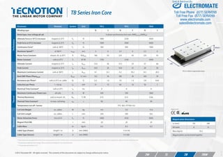
Parameter Remarks Symbol Unit TB12 TB15 TB30
Performance
Winding type N S N S N S
Motortype, max voltage ph-ph 3-phase synchronous Iron core, 400Vac rms (600Vdc)
Ultimate Force @ 10°C/s increase magnet @ 25°C Fu N 1800 2250 4500
Peak Force @ 6°C/s increase magnet @ 25°C Fp N 1600 2000 4000
Continuous Force* coils @ 100°C Fc N 760 950 1900
Maximum Speed** @ 560 V vmax m/s 3 6 2.5 6 2.5 6
Motor Force Constant mount. sfc. @ 20°C K N/Arms 186 93 225 93 225 93
Motor Constant coils @ 25°C S N2
/W 1750 2150 4300
Electrical
Ultimate Current magnet @ 25°C Iu Arms 13.0 26 13.5 33 27 66
Peak Current magnet @ 25°C Ip Arms 10.0 20 10.0 25 20 50
Maximum Continuous Current coils @ 100°C Ic Arms 4.1 8.2 4.2 10.2 8.5 20.5
Back EMF Phase-Phasepeak Bemf V / m/s 152 76 183 76 183 76
Resistance per Phase* coils @ 25°C ex. cable Rf Ω 6.3 1.6 7.6 1.3 3.8 0.65
Induction per Phase I < 0.6 Ip Lf mH 51 13 60 10 30 5
Electrical Time Constant* coils @ 25°C τe ms 8 8 8
Thermal
Maximum Continuous Power Loss all coils Pc W 430 530 1060
Thermal Resistance coils to mount. sfc. Rth °C/W 0.15 0.12 0.06
Thermal Time Constant* to max. coil temp. τth s 90 90 90
Temperature Cut-off / Sensor PTC 1kΩ / KTY83-122
Mechanical
Coil Unit Weight ex. cables W kg 4.9 5.9 11.6
Coil Unit Length ex. cables L mm 244 290 562
Motor Attraction Force rms @ 0 A Fa N 3400 4150 8300
Magnet Pitch NN τ mm 24 24 24
Cable Mass m kg/m 0.3 0.3 0.3
Cable Type (Power) length 1 m d mm (AWG) 11.9 (14)
Cable Type (Sensor) length 1 m d mm (AWG) 4.3 (26)
Magnet plate dimensions
Le (mm) 192 288
M5 bolts 8 12
Mass (kg/m) 10.5
Magnet plates can be butted together.
TB Series Iron Core
TB12 on 288mm magnet plate shown
** Actual values depend on bus voltage. Please check the F/V diagram in our simulation tool.
Allspecifications±10%
* These values are only applicable when the mounting surface is at 20°C and the motor is driven at maximum continuous current. If these values differ in your application, please check our simulation tool.
TBWTBTLTM
ELECTROMATE
Toll Free Phone (877) SERVO98
Toll Free Fax (877) SERV099
www.electromate.com
sales@electromate.com
Sold & Serviced By:
- 2. Ver.1.03
TB12
244
64 64 64
16
TB30 80 80 80 32 80 80 80
16
O 6 for M5 DIN912
R 4.6
130
12
TB192mmTB288mm
48 48 48
88°
12
48 48 48 48 48 22
288
120
12.2
O 4.3 Thermal sensor cable
130
45±0.1
MountingHeight
41
16.8
Coil unit
Magnet plate
M5 (6.5 deep)
48 48 48 48 48 48 48
384
12
2xTB192mm
568
808080
290
16
38
TB15
24
38
O 11.9 Power cable
54 160
Hole O5 (6 deep)
For Dowelpin DIN7 O5h8
Slotted Hole O5x0.5 (6 deep)
For Dowelpin DIN7 O5h8
51
51 480
208
8
Hole O5 (3 deep)
For Dowelpin DIN7 O5h8
(Optional use)
Slotted Hole O5x0.5 (3 deep)
For Dowelpin DIN7 O5h8
(Optional use)
168
192
14.2
14.2264
22
22
14.2168
192
168
65
60.5
60.5
MAGNET PLATES COIL UNITS
30
+1
-2
14
13
)peed3,x2(M 3
O 2 +0.05
0 (2x, 2.5 deep)
Optional: Digital Hall Module
5.1
6.5
Mountinginstructionsandflatnessorparallelismrequirements
canbefoundintheIronCoreinstallationmanual.CADfilesand
3Dmodelscanbedownloadedfromourwebsite.
Cable lenght 1.2 m
TBWTBTLTM
ELECTROMATE
Toll Free Phone (877) SERVO98
Toll Free Fax (877) SERV099
www.electromate.com
sales@electromate.com
Sold & Serviced By: