

Recommended
More Related Content
What's hot
What's hot (17)
Similar to JVL Profibus Expansion Modules MAC00-FP2 & MAC00-FP4
Similar to JVL Profibus Expansion Modules MAC00-FP2 & MAC00-FP4 (20)
More from Electromate
More from Electromate (20)
Recently uploaded
Recently uploaded (20)
JVL Profibus Expansion Modules MAC00-FP2 & MAC00-FP4
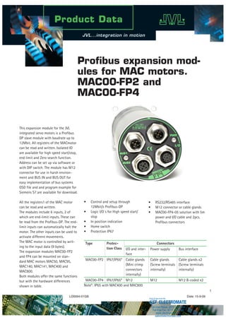
- 1. Profibus expansion mod- ules for MAC motors. MAC00-FP2 and MAC00-FP4 LD0094-01GB Date: 15-9-09 This expansion module for the JVL integrated servo motors is a Profibus DP slave module with baudrate up to 12Mbit. All registers of the MACmotor can be read and written. Isolated IO are available for high speed start/stop, end limit and Zero search function. Address can be set up via software or with DIP switch. The module has M12 connector for use in harsh environ- ment and BUS IN and BUS OUT for easy implementation of bus systems GSD file and and program example for Siemens S7 are available for download. All the registers1 of the MAC motor can be read and written. The modules include 6 inputs, 2 of which are end-limit inputs. These can be read from the Profibus-DP. The end- limit inputs can automatically halt the motor. The other inputs can be used to activate different movements. The MAC motor is controlled by writ- ing to the input data (9 bytes). The expansion modules MAC00-FP2 and FP4 can be mounted on stan- dard MAC motors MAC50, MAC95, MAC140, MAC141, MAC400 and MAC800. Both modules offer the same functions but with the hardware differences shown in table. Type Protec- tion Class Connectors I/O and inter- face Power supply Bus interface MAC00-FP2 IP67/IP65* Cable glands (Mini crimp connectors internally) Cable glands (Screw terminals internally) Cable glands x2 (Screw terminals internally) MAC00-FP4 IP67/IP65* M12 M12 M12 B-coded x2 Note*: IP65 with MAC400 and MAC800 Control and setup through 12Mbit/s Profibus-DP Logic I/O´s for High speed start/ stop In position indication Home switch Protection IP67 • • • • • RS232/RS485 interface M12 connector or cable glands MAC00-FP4-05 solution with 5m power and I/O cable and 2pcs. Profibus connectors • • • ELECTROMATE Toll Free Phone (877) SERVO98 Toll Free Fax (877) SERV099 www.electromate.com sales@electromate.com Sold Serviced By:
- 2. Connector 1 2 3 4 5 6 7 8 BUS1 (Bus in) Profibus M12 Male 5pin - A- DGND B+ SHIELD Cable Color code - green red shield BUS2 (Bus out) Profibus M12 Female 5pin - A- DGND B+ SHIELD Cable Color code green red shield PWR (Power supply) Profibus M12 Male 5 pin P+ (12-48VDC) P+ (12-48VDC) P- (GND) CV control voltage P- (GND) Cable Color code Brown White Blue Black Grey I/O Profibus M12 Female 8 pin IOC. PL or O1 Tx (RS232) Rx (RS232) GND (RS232) IOA AIN or O2 IOB IN1 or O1 IO- IOD NL or O+ Cable Color code White Brown Green Yellow Grey Pink Red Motor Connector Description The PROFIBUS DP (PROcess FIeld BUS for Decentralized Peripherals) has been around since 1989, and is a widely used fieldbus; an estimated almost 30 million Profibus devices are in operation worldwide, many of them controlled from Siemens PLCs. The bus is a high-speed serial bus using RS-485 electrical characteristics A Profibus cable uses a single twisted pair of wires plus a digital ground and shield daisy-chained to connect one master controller PLC to up to 125 slave devices, like drives and sensors. Depending on the selected speed, the cable length can be from 100 to 1200 meters at speeds from 12 megabits down to 10 kilobits/second. The most common PROFIBUS variant, PROFIBUS DP V0, uses a completely cyclical scheme to transmit data between the master and the slaves on the bus. Cycle times can go down to approximately 1 ms. PROFIBUS DP V0 is optimized for cyclic data transfers, and probably the fast- est fieldbus, relative to its bit rate, to keep large numbers of discrete values like digital and analogue inputs and outputs updated. Also its operation fits well with the traditional opera- tion of PLCs that first read all inputs in the system, then performs the needed processing and at the end updates all the outputs. For other applications, the cyclical scheme may be less optimal, espe- cially where critical process data with high priority must be delivered with the shortest delay possible. For such systems, the PROFIBUS V1 and V2, that support acyclic communications, have been designed, but these are less widely used than V0. The capabilities of a PROFIBUS slave device is presented to the PROFIBUS master device through a GSD text file, that informs of the data format, I/Os and other functions the slave device offers. During start up of a system, the slave devices are configured by the master based on this GSD file, and the system is then put into data exchange mode for operartion. PROFIBUS was defined in 1991/1993 in DIN 19245, was then included in EN 50170 in 1996 and, since 1999, established in IEC 61158/IEC 61784. The organization behind the technolo- gy is currently the PROFIBUS – PROFI- NET International organisation, (PI) at http://www.profibus.com. PROFIBUS ELECTROMATE Toll Free Phone (877) SERVO98 Toll Free Fax (877) SERV099 www.electromate.com sales@electromate.com Sold Serviced By:
- 3. P+ CV P+ P- P- 5V IN1 NL PL O+ O1 O2 IO- Tx-PD Tx Rx A- B+ DGND A+ A O1 RX B+ O2 TX B GND GND Optocoupler Optocoupler + Driver 6 2 RS232 serial interface Control core Power supply for the module Interface Control “PWR” Power supply MAC50-4: +2-48V and MAC400/800: +24V “I/O” Digital inputs and outputs Voltage range 5-28 (32)V “BUS1” Profibus Interface M12 Male connector “BUS2” Profibus Interface M12 Female connector TT2279GB MAC00-FP4 expansion module Basic MAC motor (MAC050 to 800) Power supply Internal power supply (processor and encoder) Multifunction I/O (setup as “serial data”) Status outputs Asynchronous interface (5V) Power ground (P-) is not connected in the MAC00-FP4 module Profibus Transceiver + DC-DC conv. AIN Analogue input or Zero search input ±0V nom. or up to 32V SW6 SW5 SW4 SW3 SW2 SW1 8 2 2 2 2 3 3 3 3 4 4 4 4 6 5 5 5 5 NC 7 1 1 1 1 Opto isolation NC Block diagram of MAC00-FP4 with MAC motor Easy installation with M12 con- nector JVL MACmotor expansion board MAC00-FP4 uses a standard M12 connector with 5 and 8 pin. To ease installation there is one connector for BUS In and one for BUS Out. I/O possibilities The expansion board is equipped with 6 inputs and 2 outputs, all galvani- cally isolated. Because of the limited number of pins in the M12 connector only some of the I/O´s are available in the connector. With an internal dipswitch it is possible to select be- tween O1, O2, AIN, INI, NL, PL, IO- and IO+ on 4 of the pins. Contact JVL if other configurations are required. For OEM use, a solution with cable glands (MAC00-FP2) or customer specified connector with all I/O´s sup- ported can be delivered. BUS1 Primary Profibus-DP connector. M12 - 5pin male connector including: Profibus-DP interface Expansion module MAC00-FP4 front plate PWR Power M12 - 5pin male connector including: P+, P- and secondary supply (optional). I/O M12 - 8pin female connector including: RS232 Interface Selectable I/O’s such as analogue input, O1, O2, IN1, NL, PL. BUS2 Secondary Profibus-DP connector: M12 - 5pin female connector including: Profibus-DP interface TT1008GB Easy start with sample code for Siemens S7 PLC At no additional cost the GSD files and program example for the most com- mon profibus PLC S7 from Siemens can be downloaded from www.jvl.dk. Function blocks are fully documented so they can be readily adapted for use with other PLC types. ELECTROMATE Toll Free Phone (877) SERVO98 Toll Free Fax (877) SERV099 www.electromate.com sales@electromate.com Sold Serviced By:
- 4. JVL Industri Elektronik A/S Blokken 42 DK-3460 Birkerød, Denmark Tel: +45 4582 4440 Fax: +45 4582 5550 E-mail: jvl@jvl.dk www.jvl.dk Cable and acces- sory Description M12 IP67 (Standard cable with shield) Connector Type code Picture A RS232 programming cable I/O RS232-M12-1-5-8 B Power cable PWR WI1000-M12F5VxxN C IO cable I/O WI1000-M12F8VxxN D BUS1 cable. BUS1 WI1006-M12F5SxxR E BUS2 cable. BUS2 WI1006-M12M5SxxR F Protection cap for M12 male BUS1 WI1000-M12MCAP1 G Protection cap for M12 female BUS2 or I/O WI1000-M12FCAP1 H Connector 5 pin female straight solder terminals PWR WI1008-M12F5SSC I Connector 5 pin female straight solder terminals BUS1 WI1028-M12M5SSC xx indicates cable length 05 or 20 meters (flying leads) Protection The Module is supplied with M12 con- nectors (IP67) with watertight connec- tion for use in industrial environments. Modules with other types of connector can be developed to suit customer requirements. Cables and accessories Absolute maximum rating Description Min Typ Max Absolute Max Unit CV Current@ 24VDC* 250 400 mA Voltage O+ 10 30 32 VDC Voltage P+ 12 48 50 VDC Control Voltage CV 12 48 50 VDC Input IN1-4, NL,PL 4,5 28 32 VDC Input Impedance 5.6 kOhms Input current @24V 4.3 mA Analoque input ** -10 10 32 VDC Output O1, O2 0 30 32 VDC Output current O1,O2 25 mA * Only expansion module. Remember to add the current for the basic motor ** Resolution 11bit+sign for MAC800 and 9bit+sign for MAC050-MAC141 Technical specifications Two MAC motors in a network Profibus Features Protocol type PROFIBUS DP V0 Minimum speed 9600 bits/second Maximum speed 12 megabits/second Speed selection Automatic Data format Proprietary (not PRO- FIdrive compatible) Output data length 9 bytes Input data length 8 bytes Device address selection DIP switches or soft- ware Number of digital inputs 6 (galvanically isolated) Number of digi- tal outputs 2 (galvanically isolated) ELECTROMATE Toll Free Phone (877) SERVO98 Toll Free Fax (877) SERV099 www.electromate.com sales@electromate.com Sold Serviced By: