1. LD0089-02GB Date: 25-09-14
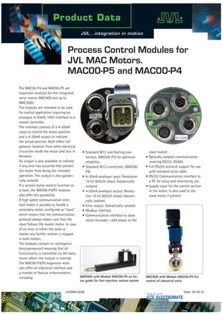
Process Control Modules for
JVL MAC Motors.
MAC00-P5 and MAC00-P4
The MAC00-P4 and MAC00-P5 are
expansion modules for the integrated
servo motors MAC400 and up to
MAC3000.
The modules are intended to be used
for control application requiring an
analogue 4-20mA, 16bit interface to a
master controller.
The interface consists of a 4-20mA
input to control the motor position
and a 4-20mA output to indicate
the actual position. Both offers full
galvanic isolation from other electrical
circuitries inside the motor and also in
between.
An output is also available to indicate
if any error has occurred that prevent
the motor from doing the intended
operation. This output is also galvani-
cally isolated.
If a second motor need to function as
a slave, the MAC00-P4/P5 modules
also offer this possibility.
A high speed communication inter-
face makes it possible to handle a
secondary motor configured as “slave”
which means that the communication
protocol always makes sure that the
slave follows the master motor. In case
of an error in either the slave or
master any further motion is stopped
in both motors.
The modules contain no intelligence
(microprocessor) meaning that all
functionality is controlled via the basic
motor where the module is inserted.
The MAC00-P4/P5 expansion mod-
ules offer an industrial interface and
a number of feature enhancements,
including:
• Standard M12 and Harting con-
nectors. (MAC00-P5) for optimum
reliability.
• Standard M12 connectors. (MAC00-
P4)
• 4-20mA analogue input. Resolution
16 bit (65535 steps). Galvanically
isolated.
• 4-20mA analogue output. Resolu-
tion 16 bit (65535 steps). Galvani-
cally isolated.
• Error output. Galvanically isolated.
• Modbus interface
• Communication interface to slave
motor (includes +24V power to the
slave motor)
• Optically isolated communication
covering RS232, RS485.
• Full RS232 protocol support for use
with standard serial cable.
• RS232 Communication interface to
a PC for setup and monitoring use.
• Supply input for the control section
in the motor. Is also used to the
slave motor if present.
MAC800 with Module MAC00-P5 on lin-
ear guide for fuel injection control system
MAC800 with Module MAC00-P5 for
control of industrial valve
ELECTROMATE
Toll Free Phone (877) SERVO98
Toll Free Fax (877) SERV099
www.electromate.com
sales@electromate.com
Sold & Serviced By:
2. Pin Connections
“CNT”- Control I/O M12 12pin female connector - Only MAC00-P4
Signal name Description Pin no.
JVL Cable WI1009
-M12M12T05N
Isolation
group
AIN- 4-20mA input. Negative terminal 1 Brown 2
AOUT2 4-20mA output. Negative terminal. 2 Blue 3
AIN+ 4-20mA input. Positive terminal 3 White 2
OUT2 Output 2. PNP ouput. 4 Green 1
IN2 / AIN1
General digital input and analogue input 1
Notice that analogue input 1 is used for Zero search
5 Pink 0
OUT1 Output 1 - Default : Error output. PNP ouput. 6 Yellow 1
IN4 General digital input 7 Black 0
IN3 / AIN2 General digital input and analogue input 2 8 Grey 0
AOUT1
4-20mA output. Positive terminal. Apply 7 to
24V to this terminal if internal AOUT supply is
disabled.
9 Red 3
P- Main ground to be used with CVI1 and IN2-4. 10 Violet 0
O+
Supply term. to the OUT1 and 2 circuitry.
Apply 5 - 32VDC
11 Grey/Pink 1
CVI1
Control supply input +12-28VDC. Consumption typical 350mA @ 24 VDC and
700mA @24VDC if a slave motor is connected. At MAC00-P4 the CVI1 is hard-
wired to the CVI terminal (pin 4) at the power connector. At MAC00-P5 the CVI1
is not present but CVI1 is internally hardwared to P+
12 Red/Blue 0
“PWR” M12 5pin male connector. Only MAC00-P4
Signal name Description Pin no.
JVL Cable I1000-
M12F5T05N
Isolation
group
P+ Main supply +12-48VDC. Connect with pin 2 * 1 Brown 1
P+ Main supply +12-48VDC. Connect with pin 1 * 2 White 1
P- Main supply ground. Connect with pin 5 * 3 Blue 1
CVI Output supply / Control voltage +12-32VDC. 4 Black 1
P- Main supply ground. Connect with pin 3 * 5 Grey 1
* Note: P+ and P- are each available at 2 terminals. Make sure that both terminals are connected in order to split the supply current in 2
terminals and thereby avoid an overload of the connector.
Expansion module MAC00-P4 front plate
COM
Communication
M12 - 5pin female
connector including:
RS232 and Slave
RS485 interface *
TT1195GB
SLV
Slave Connector
M12 - 5pin male
connector including:
and supply
for the slave motor.
RS485 CVI2
CNT
Basic I/O’s
M12 - 12pin female
connector including:
4-20mA in- and out
and 2 outputs and 2
analogue inputs
PWR
Power supply
M12 - 5pin male
connector including:
(supply), and
(output supply) and
P+ CVI1
P-
ELECTROMATE
Toll Free Phone (877) SERVO98
Toll Free Fax (877) SERV099
www.electromate.com
sales@electromate.com
Sold & Serviced By:
3. “COM” Communication connector-M12-5pin female connector MAC00-P5 and MAC00-P4
Signal name Description
Pin
no.
JVL Cable RS232-
M12-1-5-5
Isolation
group
RS232:RX RS232 interface. Receive terminal. Leave open if unused. 1 Brown 4
RS232:TX RS232 interface. Transmit terminal. Leave open if unused. 2 Whitw 4
RS485: A- RS485 interface. Leave open if unused. 3 Blue 4
RS485: B+ RS485 interface. Leave open if unused. 4 Black 4
IGND Ground intended to be used together with the other signals in the connector. 5 Grey 4
“SLV”-Slave connector-M12-5pin male connector MAC00-P5 and MAC00-P4
Signal name Description
Pin
no.
JVL Cable WI1005-
M12F5TF5T03P
Isolation
group
RS485: A- RS485 Modbus. Positive data signal. 1 1 4
CVI2 Supply output (optionally input) +12-28VDC. Hardwired internally to CVI1 2 2 0
GND
Ground to be used with CVI2. This ground is hardwired internally to the main
power ground P-.
3 3 0
RS485: B+ RS485 Modbus. Negative data signal. 4 4 4
IGND Ground intended to be used together with the other signals in the connector. 5 Screen wire 4
“CNT” - Control I/O. Harting 3HAN-8-pin male connector - Only MAC00-P5
Signal
name
Description Pin
no.
JVL Cable
WG1105
Isolation
group*
AIN+ 4-20mA input. Positive terminal 1 Blue 2
AIN- 4-20mA input. Negative terminal 2 Red 2
AOUT+
4-20 mA output. Positive terminal. Apply 7 to 24V to this terminal if internal AOUT supply is
disabled.
3 Grey 3
AOUT- 4-20mA output. Negative terminal. 4 Yellow 3
O+ Supply term. to the error output. Apply 24VDC. 5 Green 1
OUT1 Error output. PNP output. 6 Brown 1
P+ (CVI1)
Control supply input +12-28VDC. Consumption typically 350mA@24VDC and
700mA@24VDC if a slave motor is connected. At MAC00-P5 the CVI1 is not present but
CVI1 is internally hardwared to P+.
7 White 0
P- Main ground to be used with CVI1 and CVI2. 8 Black 0
* Note: Isolation group indicate which terminals/circuits that a galvanic connected to each other. In other words group 1, 2, 3 and 4 are all
fully independantly isolated from each other. Group 0 correspond to the housing of the motor which may also be connected to earth via
the 115/230VAC power inlet.
Expansion module MAC00-P5 front plate
Slave connection (SLV)
M12 - 5pin male
connector includes:
- RS485 modbus
- 24VDC to slave
Communication (COM)
M12 - 5pin female
connector includes:
- RS232 interface
- RS485 Modbus (same as SLV)
Control I/O (CNT)
Harting 3HAN 8pin male
Contains
- 4-20mA input
- 4-20mA output
- Error output
- 24VDC supply input
TT1165GB
ELECTROMATE
Toll Free Phone (877) SERVO98
Toll Free Fax (877) SERV099
www.electromate.com
sales@electromate.com
Sold & Serviced By:
4. Specifications
Analogue In/Output 16bit/65535 steps
P+ +12-32VDC
CVI +12-32VDC
IO+ 5-32VDC
RS232 9.6kbit -230.4kbit
RS485 (Modbus) 9.6kbit - 1 Mbit
Accessories
RS232-M12-1-5-5 RS232 Interface Cable. Length 5m.
WI1005-M12F5TF5T03P Master to slave communica-
tion cable for syncronization.
Length 3m.
WI1000-M12F5T05N M12 Cable for power supply.
Female 5 pin. Length 5m.
WG1105 Pwr/IO Cable with Harting connector. Length 5m.
Block Diagram
JVL Industri Elektronik A/S
Blokken 42
DK-3460 Birkerød, Denmark
Tel.: +45 4582 4440
E-mail: jvl@jvl.dk www.jvl.dk
JVL Deutschland
Tel.: +49 7121 137 7260
E-mail: jan.tausend@jvl.dk
www.jvldrives.de
JVL USA
Tel.: +1 513/877-3134
E-mail: mfisher@jvlusa.com
www.jvlusa.com
JVL Turkey
Tel.: +90 216 3891644
email: ozkan.ozel@jvl.dk
www.jvl.dk
P+
AIN1/2
P+
P-
CVI1
CVI2
P-
GND
O1
RX
O2
TX
IO1-4
GND
GND
Rx
IGND
Tx
Control
Supply
Asynchronous
serial interface
Power supply
P+ : +12-32V
+12-32VCVI1/CVI2 :
RS485 Interface
(Closed protocol -
not for general use)
4-20mA output
4-20mA Input
Status outputs
(OUT2 only at
MAC00-P4)
Inputs for
general use
(only at MAC00-P4)
Supply output
(to/from slave motor)
RS485 Termination dipswitch
Internal supply ON/OFF
RS232 Interface
Basic MAC motor with MAC00-P4 or P5 module inserted.
TT1169-03GB
MAC00-Px expansion module
Basic MAC motor
(MAC400, 800, 1500 or 3000)
Power supply
Analogue input
(standard)
Multifunction I/O 1
(Bidirectional)
Multifunction I/O 2
(Bidirectional)
I/O channel
(Bidirectional)
Isolation zone 4
Isolation zone 3
Isolation zone 2
Isolation zone 1
Each isolation zone have not galvanic contact with any other circuitry.Only available at MAC00-P4
Status outputs
Not used
Not used
“CVI1” do not exist at MAC00-P5
int. supply is wired to “P+ ”
Asynchronous
interface
Fuse F10A
A-
AOUT1
AIN
IO+
B+
AOUT2
AIN
IN2-4/
AIN1/2
OUT1/2
2 channel
differential
Transceiver
4-20mA
Output
16bit resolution
4-20mA
Input
16bit resolution
Status
Outputs
(PNP)
Digital and
analog input
for general use
A1+ /-
B1+ /-
A2+ /-
B2+ /-
Galvanic
isolation
I/Ocontroland
galvanicisolation
3
2
3
2
ELECTROMATE
Toll Free Phone (877) SERVO98
Toll Free Fax (877) SERV099
www.electromate.com
sales@electromate.com
Sold & Serviced By: