Cloud Frontiers: A Deep Dive into Serverless Spatial Data and FME
Amp pdo2035 stepper_drive_specsheet
1. STEPPER
SYSTEMS
18
PDO2035StepperDrivewithDigitalOscillator
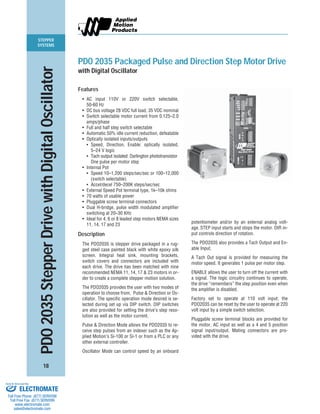
PDO 2035 Packaged Pulse and Direction Step Motor Drive
with Digital Oscillator
Features
• AC input 110V or 220V switch selectable,
50-60 Hz
• DC bus voltage 28 VDC full load, 35 VDC nominal
• Switch selectable motor current from 0.125–2.0
amps/phase
• Full and half step switch selectable
• Automatic 50% idle current reduction, defeatable
• Optically isolated inputs/outputs
• Speed, Direction, Enable: optically isolated,
5–24 V logic
• Tach output isolated: Darlington phototransistor
One pulse per motor step
• Internal Pot
• Speed 10–1,200 steps/sec/sec or 100–12,000
(switch selectable)
• Accel/decel 750–200K steps/sec/sec
• External Speed Pot terminal type, 1k–10k ohms
• 70 watts of usable power
• Pluggable screw terminal connectors
• Dual H-bridge, pulse width modulated amplifier
switching at 20–30 KHz
• Ideal for 4, 6 or 8 leaded step motors NEMA sizes
11, 14, 17 and 23
Description
The PDO2035 is stepper drive packaged in a rug-
ged steel case painted black with white epoxy silk
screen. Integral heat sink, mounting brackets,
switch covers and connectors are included with
each drive. The drive has been matched with nine
recommended NEMA 11, 14, 17 & 23 motors in or-
der to create a complete stepper motion solution.
The PDO2035 provides the user with two modes of
operation to choose from, Pulse & Direction or Os-
cillator. The specific operation mode desired is se-
lected during set up via DIP switch. DIP switches
are also provided for setting the drive’s step reso-
lution as well as the motor current.
Pulse & Direction Mode allows the PDO2035 to re-
ceive step pulses from an indexer such as the Ap-
plied Motion’s Si-100 or Si-1 or from a PLC or any
other external controller.
Oscillator Mode can control speed by an onboard
potentiometer and/or by an external analog volt-
age. STEP input starts and stops the motor. DIR in-
put controls direction of rotation.
The PDO2035 also provides a Tach Output and En-
able Input.
A Tach Out signal is provided for measuring the
motor speed. It generates 1 pulse per motor step.
ENABLE allows the user to turn off the current with
a signal. The logic circuitry continues to operate,
the drive “remembers” the step position even when
the amplifier is disabled.
Factory set to operate at 110 volt input; the
PDO2035 can be reset by the user to operate at 220
volt input by a simple switch selection.
Pluggable screw terminal blocks are provided for
the motor, AC input as well as a 4 and 5 position
signal input/output. Mating connectors are pro-
vided with the drive.
ELECTROMATE
Toll Free Phone (877) SERVO98
Toll Free Fax (877) SERV099
www.electromate.com
sales@electromate.com
Sold & Serviced By:
2. STEPPER
SYSTEMS
19
POWER AMPLIFIER:
AMPLIFIER TYPE ....................................... Bipolar Darlington dual H-Bridge.
CURRENT CONTROL .................................. Recirculating, pulse width modulated, switching at 20–30 KHz.
OUTPUT CURRENT .................................... 0.125–2.0 amps, dip switch selectable.
DC BUS VOLTAGE ...................................... 35 VDC.
AC INPUT VOLTAGE ................................... 110 or 220 VAC (switch selectable) 50/60 Hz.
MAXIMUM OUTPUT POWER ..................... 70 Watts.
IDLE CURRENT REDUCTION...................... Automatic 50% idle current reduction, defeatable.
MOTOR RESOLUTION ................................ Full or half step switch selectable
STATUS LED’S............................................ AC power (red).
CONTROLLER SECTION:
DIGITAL OSCILLATOR ................................ Precise speed control with automatic ramps between speeds. The
accel/decel rates are set by an on board potentiometer, and are ad-
justable from 10 to 12,000 steps/sec/sec.
SPEED SETTINGS AND RANGE.................. On-Board: Speed potentiometer. High speed: 100–12,000 steps/
sec/sec. Low speed: 10–1,200 steps/sec/sec.
External: External potentiometer capable.
MODES OF OPERATION ............................. Two modes dip switch selectable:
Pulse and Direction: works with pulse and direction controllers
Oscillator: on-board potentiometers and/or an external 0–5 V ana-
log voltage, control speed.
STEP AND DIRECTION INPUTS ................. Optically isolated: 5–24 VDC. Steps requires a 10 microsecond
minimum pulse width. The direction signal setup time is 50 micro-
second minimum.
SYSTEM SPECIFICATIONS:
OVERALL SIZE ........................................... 1.75˝ x 4.00˝ x 6.80˝.
CHASSIS MATERIAL .................................. Aluminum, black anodized with integral heat sink.
CASE .......................................................... Steel with black paint and white epoxy silk screen. Includes switch
covers.
WEIGHT...................................................... 3 lbs.
AMBIENT TEMPERATURE .......................... 0˚ to 50˚C (32˚ to 122˚F).
HUMIDITY .................................................. Maximum of 90% non-condensing.
CONNECTORS ............................................ Screw terminal connectors for input power and motor, and input/
output signals.
MOTORS .................................................... Can drive 4, 6 or 8 lead motors, NEMA sizes 11– 23.
PDO 2035 Technical Specifications
ELECTROMATE
Toll Free Phone (877) SERVO98
Toll Free Fax (877) SERV099
www.electromate.com
sales@electromate.com
Sold & Serviced By:
3. STEPPER
SYSTEMS
20
connector
enable, direction, step
dip switches
full/half step
current setting
power LED
motor connector
AC power connector
PDO 2035 Connectors and Switches
INPUTS (4 pin)
position no.
1 en
2 dir
3 com
4 step
MOTOR
position no.
1 B–
2 B+
3 A–
4 B+
AC POWER
position no.
1 G
2 N
3 L
connector
exterior speed
trimpots
speed, accel, decel
dip switches
oscillator set up
INPUTS (5 pin)
position no.
1 tach–
2 tach+
3 wpr
4 ccw
5 cw
ELECTROMATE
Toll Free Phone (877) SERVO98
Toll Free Fax (877) SERV099
www.electromate.com
sales@electromate.com
Sold & Serviced By:
4. STEPPER
SYSTEMS
21
A+
A–
B+
B–
step
direction
110/220
enable
tach
out
Optical
Isolators
external speed pot
common
Step
Sequencer
Oscillator
current setting
full step/
half step
step
dir
accel
decel
speed adj
to
motor
Power
Supply
VAC
Amplifier
osc
options
1
123
2345
PDO 2035 Technical Drawings
BLOCK DIAGRAM
MECHANICAL OUTLINE
DIR
EN
COM
STEP
TACH+
TACH-
WPR
CCW
CW
123
12345
PDO 2035
Step Motor Driver
POWER
HALF
STEP
B–
B+
A–
A+
GND
N
L
HILO
BYPASS
INTEXT
FULL
STEP
SPEED
DECEL
ACCEL
MOTOR
ACPOWER
1000
500
250
125
CURRENT
(BASE=125mA)
6.80"
.245"
4.00"
.273"
1.75"
.19"
6.00"
ELECTROMATE
Toll Free Phone (877) SERVO98
Toll Free Fax (877) SERV099
www.electromate.com
sales@electromate.com
Sold & Serviced By:
5. STEPPER
SYSTEMS
22
NEMA 11, 14, 17 Motor Data
NEMA 11, 14, 17 Motor Dimensions
RECOMMENDED MOTORS FOR PDO 2035
FEATURES 11 11 14 17 17 17
Motor P/N: 11012 11013 14842 17068 17071 17075
Motor Current amps 1.00 1.00 1.00 1.34 1.70 1.70
Resistance Ohms 1.40 2.00 4.30 2.10 1.70 1.70
Holding Torque oz-in 7.4 15.3 26 31.4 51 62.6
Rotor Inertia oz-in2
0.044 0.098 0.109 0.19 0.29 0.37
Bearings
Thrust Load (lbs) 3.0 3.0 3.0 3.0 3.0 3.0
Radial Load (lbs) 5.0 5.0 5.0 5.0 5.0 5.0
Radial Play inch/lbs .001 max .001 max .0004 max .0008 max .0008 max .0008 max
@ 1 lb @ 1 lb @ 1 lb @ 1 lb @ 1 lb @ 1 lb
End Play inch/lbs .003 max .003 max .0004 max .003 max .003 max .003 max
@ 2 lbs @ 2 lbs @ 2 lbs @ 2.2 lbs @ 2.2 lbs @ 2.2 lbs
Weight lbs. 0.26 0.39 0.47 0.44 0.57 0.73
Motor current, resistance and torque ratings are with parallel connection
NEMA 17
Model L
17068 1.30˝
17071 1.54˝
17075 1.85˝
12" min
4 X #4 – 40
.17 DEEP
2 X 1.220
2 X 1.65
Ø.866
+.000
–.001
L
.59
.080
.59 ± .01
Ø.1968
.79±.02
+.0000
–.0004
FLAT
.177±.006
.177±.006
FLAT
TYP
NEMA 14
Model L
14842 1.57˝
12" min
2 X 1.024
2 X 1.38
2 X #4 – 40
Ø.866
+.000
–.001
L
.059
Ø.1968
+.0000
–.0004
.559 ± .014
.39
2 X .25
TYP
4 X M2.6 X .45
.118 MIN
7.9" MIN
2 X .906 ± .018
Ø.866
+0
–.001
L
.06 ± .008
Ø.1968
.02 X 45˚
+0
–.0005
.787 ± .02
.394 ± .04 2 X 1.10 ± .012
NEMA 11
Model L
11012 1.32˝
11013 1.87˝
ELECTROMATE
Toll Free Phone (877) SERVO98
Toll Free Fax (877) SERV099
www.electromate.com
sales@electromate.com
Sold & Serviced By:
6. STEPPER
SYSTEMS
23
Torque Curves
PDO 2035 with NEMA 11, 14, 17 Step Motors
17075 MOTOR
Motor Connection: Parallel
Drive Setting: Full, Half Step • 1.7 A/Phase
Dynamic
Torque
(oz-in)
rev/sec
0 5 10 15 20 25 30 35 40
0
10
20
30
40
50
60
Full
Half
14842 MOTOR
Motor Connection: Parallel
Drive Setting: Full, Half Step • 1.0 A/Phase
Dynamic
Torque
(oz-in)
rev/sec
0 5 10 15 20 25 30 35 40
0
5
10
15
20
25
Full
Half
17068 MOTOR
Motor Connection: Parallel
Drive Setting: Full, Half Step • 1.375 A/Phase
Dynamic
Torque
(oz-in)
rev/sec
0 5 10 15 20 25 30 35 40
0
5
10
15
20
25
30
35
Full
Half
11012 MOTOR
Motor Connection: 4 Lead Bipolar
Drive Setting: Full, Half Step • 1.0 A/Phase
Dynamic
Torque
(oz-in)
rev/sec
0 5 10 15 20 25 30 35 40
0
5
10
Full
Half
11013 MOTOR
Motor Connection: 4 Lead Bipolar
Drive Setting: Full, Half Step • 1.0 A/Phase
Dynamic
Torque
(oz-in)
rev/sec
0 5 10 15 20 25 30 35 40
0
3
6
9
12
15
Full
Half
17071 MOTOR
Motor Connection: Parallel
Drive Setting: Full, Half Step • 1.75 A/Phase
Dynamic
Torque
(oz-in)
rev/sec
0 5 10 15 20 25 30 35 40
0
10
20
30
40
50
Full
Half
ELECTROMATE
Toll Free Phone (877) SERVO98
Toll Free Fax (877) SERV099
www.electromate.com
sales@electromate.com
Sold & Serviced By:
7. STEPPER
SYSTEMS
24
NEMA 23 Motor Data
NEMA 23 Motor Dimensions
FEATURES RECOMMENDED MOTORS FOR PDO 2035
Motor P/N: 23394 23397 23400
Motor Current amps 2.83 2.83 2.83
Resistance Ohms 0.07 0.90 1.10
Holding Torque oz-in 77 177 264
Rotor Inertia oz-in2
0.66 1.64 2.62
Bearings
Thrust Load (lbs) 25 25 25
Radial Load (lbs) 15 15 15
Radial Play inch/lbs .001 max .001 max .001 max
@ 1 lb @ 1 lb @ 1 lb
End Play inch/lbs .003 max .003 max .003 max
@ 2.2 lbs @ 2.2 lbs @ 2.2 lbs
Weight lbs. 1.00 1.54 2.20
Motor current, resistance and torque ratings are with parallel connection
Model L
23393 1.54˝
23396 2.13˝
23399 2.99˝
18.00 MIN
2 X 1.856
2 X 0.928
0.228 ± 0.006
FLAT
Ø1.50 ± 0.001
4 X Ø0.205 ± 0.01
2 X 2.22
+0.000
–0.001
.59± 0.01
L
.197
.063 ± 0.008
.591 ± 0.01
Ø.250
0.630 ± .039 .787 ± .020
.228 ±.006
FLAT
2 X 1.11
MOUNTING
END
TYP
ELECTROMATE
Toll Free Phone (877) SERVO98
Toll Free Fax (877) SERV099
www.electromate.com
sales@electromate.com
Sold & Serviced By:
8. STEPPER
SYSTEMS
25
Torque Curves
PDO 2035 with NEMA 23 Step Motors
23394 MOTOR
Motor Connection: Parallel
Drive Setting: Full, Half Step • 2.0 A/Phase
Dynamic
Torque
(oz-in)
rev/sec
0 5 10 15 20 25 30 35 40
0
10
20
30
40
Full
Half
23397 MOTOR
Motor Connection: Parallel
Drive Setting: Full, Half Step • 2.0 A/Phase
Dynamic
Torque
(oz-in)
rev/sec
0 5 10 15 20 25 30 35 40
0
20
40
60
80
100
Full
Half
23400 MOTOR
Motor Connection: Parallel
Drive Setting: Full, Half Step • 2.0 A/Phase
Dynamic
Torque
(oz-in)
rev/sec
0 5 10 15 20 25 30 35 40
0
50
100
150
200
Full
Half
ELECTROMATE
Toll Free Phone (877) SERVO98
Toll Free Fax (877) SERV099
www.electromate.com
sales@electromate.com
Sold & Serviced By:
9. STEPPER
SYSTEMS
26
PDO2035OrderingInformation
DRIVE ONLY ORDERING
Drive Type Description
PDO 2035 Packaged 2.0 amps, 35 VDC, 110/220 VAC input.
Pulse & direction/oscillator drive.
System Ordering Example: PDO 2035 - 17068
COMPLETE SYSTEM ORDERING
Drive Type Motor System Number Step Motor Description
PDO 2035 11012 NEMA 11 high torque one stack
11013 NEMA 11 high torque two stack
14842 NEMA 14 two stack
17068 NEMA 17 high torque one stack
17071 NEMA 17 high torque two stack
17075 NEMA 17 high torque three stack
23394 NEMA 23 high torque one stack
23397 NEMA 23 high torque two stack
23400 NEMA 23 high torque three stack
ELECTROMATE
Toll Free Phone (877) SERVO98
Toll Free Fax (877) SERV099
www.electromate.com
sales@electromate.com
Sold & Serviced By: