DevEX - reference for building teams, processes, and platforms
Applied motion products pdo 5580 datasheet
1. STEPPER
SYSTEMS
PDO 5580 Stepper Drive with Digital Oscillator
48
Sold & Serviced By:
ELECTROMATE
Toll Free Phone (877) SERVO98
Toll Free Fax (877) SERV099
www.electromate.com
sales@electromate.com
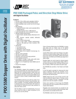
PDO 5580 Packaged Pulse and Direction Step Motor Drive
wih Digital Oscillator
Features
• AC input 110V or 220V switch selectable, 50-60 Hz
• DC bus voltage 75 VDC full load, 80 VDC nominal
• Switch selectable motor current from 0.5–5.5 amps/
phase
• Microstepping:
• Pulse and Direction mode: switch selectable 200 to
50,800 steps/rev
• Oscillator/Joystick mode: 12,800 steps/rev
• Switch selectable idle current reduction, 0 or 50%
• Optically isolated inputs/outputs
• Speed, Enable: optically isolated, differential 5–24 V
logic
• Step, Direction: optically isolated, differential
5–12 V logic
• Wiper: 0–5VDC analog signal
• Tach & Fault output: isolated phototransistor.
Output is 100 pulses per motor revolution, 50%
duty cycle.
• Internal Pot:
• Low speed 0–5 rps
• High speed 0–25 rps
• Accel/decel 1–250 rev/sec/sec
• External Speed, Pot or Joystick 3 terminal type, 1k–
10k ohms
• Self test, switch selectable
• 440 watts of usable power
• Overtemp, overcurrent and surge protection
• Screw terminal connectors
• Dual, MOSFET H-bridge, 3 state, pulse width modu-lated
amplifier switching at 20–30 KHz
• Ideal for 4, 6 or 8 leaded step motors NEMA sizes 23
or 34
• CE and TUV compliant
Description
The PDO5580 is stepper drive packaged in a rugged
steel case painted black with white epoxy silkscreen. In-tegral
heat sink, mounting brackets, switch covers and
connectors are included with each drive. The drive has
been matched with twelve recommended NEMA 23 and
34 motors in order to create a complete stepper motion
solution.
The PDO5580 provides the user with four modes of op-eration
to choose from, Self test, Pulse & Direction, Joy-stick
or Oscillator. The specific operation mode desired
is selected during set up via DIP switch. DIP switchs are
also provided for setting the drive’s step resolution as
well as the motor current.
Self Test Mode is used for troubleshooting. If you are
unsure about the motor or signal connections to the
drive you can use the self-test.
Pulse & Direction Mode allows the PDO5580 to receive
step pulses from an indexer such as the Applied
Motion’s Si-100 or Si-1, or from a PLC or any other ex-ternal
controller.
Joystick Mode allows speed and direction to be deter-mined
by an external analog voltage. STEP and DIR in-puts
can be used for limit switches. SPEED input selects
speed range. LO SPEED and HI SPEED pots adjust the 2
speed ranges.
Oscillator Mode can control speed by onboard potenti-ometers
and/or by an external analog voltage. STEP in-put
starts and stops the motor. DIR input controls direc-tion
of rotation. SPEED input selects the speed range.
The PDO5580 also provides a Tach Output and Enable
Input.
A Tach Out signal is provided for measuring the motor
speed. It generates 100 pulses per revolution. If con-nected
to a frequency counter, speed reads out in revs/
second with two decimal places.
ENABLE allows the user to turn off the current to the
motor by setting this signal to logic 0. The logic circuitry
continues to operate, the drive “remembers” the step
position even when the amplifier is disabled.
Factory set to operate at 110-volt input; the PDO5580
can be reset by the user to operate at 220-volt input by a
simple switch selection.
Pluggable screw terminal blocks are provided for the
motor, AC input and 8-position signal input/output. Mat-ing
connectors are provided with the drive.
The PDO5580 is both CE and TUV compliant.
2. STEPPER
SYSTEMS
49
PDO 5580 Technical Specifications
Sold & Serviced By:
POWER AMPLIFIER:
AMPLIFIER TYPE ....................................... MOSFET, dual H-Bridge, all parts rated for 100 volts.
CURRENT CONTROL .................................. 3 state, pulse width modulated, switching at 20–30 KHz.
OUTPUT CURRENT .................................... 0.5 to 5.5 amps/phase output current, switch selectable in 0.2
increments.
POWER SUPPLY ........................................ Linear, toroidal transformer for high reliability and low noise. 110
or 220 VAC input, switch selectable. 50–60 Hz.
DC BUS VOLTAGE ...................................... DC voltage at nominal line voltage: 75 VDC full load, 90 VDC no
load.
AC INPUT VOLTAGE ................................... 110 or 220 VAC (switch selectable) 50–60 Hz.
MAXIMUM OUTPUT POWER ..................... 440 Watts.
PROTECTION CIRCUITS ............................. Short circuit and over temperature.
IDLE CURRENT REDUCTION...................... 0% or 50% dip switch selectable.
MOTOR RESOLUTION ................................ Oscillator/joystick modes: 1/64 step (12,800 s/r) with 1.8° motor.
Pulse & direction mode: 16 switch selectable resolutions: 200,
400, 1000, 2000, 5000, 10000, 12800, 18000, 20000, 21600,
2500, 25400, 25600, 36000, 50000, 50800 steps/rev.
CONTROLLER SECTION:
MODE OF OPERATION ............................... Self Test: Used for trouble shooting to test motor and/or signal
connections.
Pulse & Direction: Allows amplifier to receive step pulses from a
controller such as Applied’s Si-100 or Si-1, or any other pulse
source PLC or controller.
Joystick: allows speed and direction to be determined by an exter-nal
analog voltage. Step and Dir inputs can be used for limit
switches. Speed input selects speed range. LO SPEED and HI
SPEED pots adjust the 2 speed ranges.
Digital Oscillator: allows for precise speed control with automatic
ramps between speeds. Accel/Decel rates are set by on board po-tentiometer
and/or external analog voltage.
STEP AND DIRECTION INPUT .................... Optically isolated: 5-12 VDC
SPEED RANGE ........................................... LO speed range: 0-5 rev/sec.
HIGH speed range: 0-25 rev/sec
Accel/decel range: 1-250 rev/sec/sec
TACH OUPUT .............................................. Optically isolated phototransistor. 30 VDC, 20mA max.
SYSTEM SPECIFICATIONS:
OVERALL SIZE ........................................... 3 x 5.3 x 8 inches. See mechanical outline.
CHASSIS MATERIAL .................................. Aluminum, black anodized with integral heat sink.
WEIGHT ...................................................... 7.8 lbs.
AMBIENT TEMPERATURE .......................... 0° to 70°C.
HUMIDITY .................................................. Maximum of 90% non-condensing.
CONNECTORS ............................................ Screw terminal connectors for input power and motor, and I/O sig-nals.
MOTORS .................................................... Can drive 4, 6 or 8 lead motors, NEMA sizes 23 & 34.
CASE .......................................................... Steel with black paint and white epoxy silk screen. Integral heat
sink, mounting brackets & switch covers included.
AGENCY APPROVAL .................................. CE & TUV.
ELECTROMATE
Toll Free Phone (877) SERVO98
Toll Free Fax (877) SERV099
www.electromate.com
sales@electromate.com
3. STEPPER
SYSTEMS
50
PDO 5580 Technical Drawings
MECHANICAL OUTLINE
BLOCK DIAGRAM
DIR+
DIR–
STEP+
STEP–
EN+
EN–
FAULT+
FAULT–
POWER TEMP
JOYSTICK
EXT SPEED
50% IDLE
0.2
0.4
0.8
1.6
2.0
CURRENT
(BASE = 0.5 A)
HIGH SPEED
LOW SPEED
ACCEL
OSC BYPASS
SELF TEST
B–
B+
A–
A+
MOTOR
PD0 5580
SHORT
STEPS/REV
SPEED+
SPEED-TACH+
TACH–
CW
WPR
CCW
Step Motor Driver
G
N
L
AC
POWER
90V pk
1 2 3 4 5 6 7 8 1 2 3 4 5 6
3.07 "
8.00 "
1.25 "
5.45 "
5.30 "
2.02 "
0.25"
0.06"
2.15"
3.00 "
8.97 " 9.25 "
motor phase A motor phase B
EXT
SPEED
INPUT
current
0.5 to5.5
A/phase
joystick
ext speed
50% idle
fuse
LO accel
speed
110 or
220 VAC
HI
speed
Microstep
Sequencer
Digital Oscillator
&
STEP
Joystick Interface
Internal
Power
Supply
power LED
MOSFET
3 State
PWM
Power
Amplifier
DIRECTION
HI/LO SPEED
ENABLE
TACH
Optical
Isolation
steps/rev
osc bypass
self test
Fault
Monitor
Optical
Isolation
overcurrent LED overtemp LED
FAULT OUT
Sold & Serviced By:
ELECTROMATE
Toll Free Phone (877) SERVO98
Toll Free Fax (877) SERV099
www.electromate.com
sales@electromate.com
4. STEPPER
SYSTEMS
51
Sold & Serviced By:
ı/o connector
direction/step/enable/fault
status LEDs
power/overtemp fault/motor short
switches
motor current/idle current/
external pot/joystick mode
motor connector
switches
steps per rev/osc mode/self test
AC power connector
PDO 5580 Connectors and Switches
INPUTS
position no.
1 speed+
2 speed–
3 tach+
4 tach–
5 cw+
6 wpr–
7 ccw+
MOTOR
position no.
1 B–
2 B+
3 A–
4 B+
AC POWER
position no.
1 G
2 N
3 L
ı/o connector
speed/tach out/ external pot/
joystick/0–5 V analog speed
potentiometers
accel/decel rate
low speed/high speed
INPUTS
position no.
1 dir+
2 dir–
3 step+
4 step–
5 en+
6 en–
7 fault+
8 fault–
ELECTROMATE
Toll Free Phone (877) SERVO98
Toll Free Fax (877) SERV099
www.electromate.com
sales@electromate.com
5. STEPPER
SYSTEMS
52
NEMA 23 Motor Data
Sold & Serviced By:
FEATURES RECOMMENDED MOTORS FOR PDO 5580
Motor P/N: 23122 23123 23124 23395 23398 23401
Motor Current amps 2.00 2.50 3.50 4.24 4.24 4.24
Resistance Ohms 1.24 1.18 0.82 0.32 0.38 0.50
Holding Torque oz-in 98 158 225 77 177 264
Rotor Inertia oz-in2 0.55 1.14 1.72 0.66 1.64 2.62
Bearings
Thrust Load (lbs) 25 25 25 25 25 25
Radial Load (lbs) 15 15 15 15 15 15
Radial Play inch/lbs .001 max .001 max .001 max .001 max .001 max .001 max
@ 1 lb @ 1 lb @ 1 lb @ 1 lb @ 1 lb @ 1 lb
End Play inch/lbs .001 max .001 max .001 max .003 max .003 max .003 max
@ 9 lbs @ 9 lbs @ 9 lbs @ 2.2 lbs @ 2.2 lbs @ 2.2 lbs
Weight lbs. 1.17 2.00 2.80 1.00 1.54 2.20
Motor current, resistance and torque ratings are with parallel connection
NEMA 23 Motor Dimensions
Model L
23122 2.00˝
23123 3.00˝
23124 4.00˝
Model L
23395 1.54˝
23398 2.13˝
23401 2.99˝
.75
L
.81 ± .03
.190
.060
18" min
2 x Ø.2500 +.0000
–.0005
Ø1.5 ± .002
2 X 1.856
2 X 2.22
4 X Ø.205 ± .01
MOUNTING
END
18.00 MIN
2 X 0.928
2 X 1.856
Ø1.50 ± 0.001
0.228 ± 0.006
FLAT
4 X Ø0.205 ± 0.01
2 X 2.22
+0.000
–0.001
.59± 0.01
L .197
.063 ± 0.008
.591 ± 0.01
Ø.250
.228 ±.006
FLAT
0.630 ± .039 .787 ± .020
2 X 1.11
MOUNTING
END
TYP
ELECTROMATE
Toll Free Phone (877) SERVO98
Toll Free Fax (877) SERV099
www.electromate.com
sales@electromate.com
9. STEPPER
SYSTEMS
56
DRIVE ONLY ORDERING
System Ordering Example: PDO 5580 - 23122
Drive Type Description
PDO 5580 Packaged 5.5 amps, 80 VDC, 110/220 VAC input.
Microstepping pulse & direction/oscillator drive.
Si5580 Packaged 5.5 amps, 80 VDC, 110/220 VAC input.
Sold & Serviced By:
Microstepping fully programmable drive/indexer with Si™ software.
PDO 5580 Ordering Information
COMPLETE SYSTEM ORDERING
Drive Type Motor System Number Step Motor Description
PDO 5580 23122 NEMA 23 one stack
Si5580 23123 NEMA 23 two stack
23124 NEMA 23 three stack
23395 NEMA 23 high torque one stack
23398 NEMA 23 high torque two stack
23401 NEMA 23 high torque three stack
34348 NEMA 34 one stack
34349 NEMA 34 two stack
34350 NEMA 34 three stack
34474 NEMA 34 high torque one stack
34476 NEMA 34 high torque two stack
34478 NEMA 34 high torque three stack
ELECTROMATE
Toll Free Phone (877) SERVO98
Toll Free Fax (877) SERV099
www.electromate.com
sales@electromate.com