
Recommended
More Related Content
Similar to Defect reduction
Similar to Defect reduction (20)
Recently uploaded
Recently uploaded (20)
Defect reduction
- 1. US 2008004.7300A1 (19) United States (12) Patent Application Publication (10) Pub. No.: US2008/0047300 A1 Rhoads (43) Pub. Date: Feb. 28, 2008 (54) DEFECT REDUCTION IN MANUFACTURE Related U.S. Application Data GLASS SHEETS BY FUSION PROCESS (63) Continuation ofapplication No. 10/859.366, filed on Jun. 2, 2004, now abandoned. (76) Inventor: Randy L. Rhoads, Horseheads, NY (US) Publication Classification (51) Int. Cl. Correspondence Address: CO3B 9/00 (2006.01) CORNING INCORPORATED (52) U.S. Cl. .................................................................. 65/53 SP-T-3-1 CORNING, NY 14831 (57) ABSTRACT Methods and apparatus for manufacturing glass sheets are (21) Appl. No.: 11/974,268 provided. The apparatus includes an inlet for delivering glass to a trough formed in a refractory body. The lowest (22) Filed: Oct. 12, 2007 point in the trough is located on the end opposite inlet end.
- 2. Patent Application Publication Feb. 28, 2008 Sheet 1 of 3 US 2008/004.7300 A1 FIG. 1 PRIOR ART
- 3. US 2008/004.7300 A1 FIG. 2 Patent Application Publication Feb. 28, 2008 Sheet 2 of 3
- 4. Patent Application Publication Feb.28,2008 Sheet 3 of3 US2008/0047300 A1 FIG. 4 58 // k
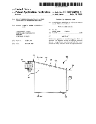
- 5. US 2008/0047300 A1 DEFECT REDUCTION IN MANUFACTURE GLASS SHEETS BY FUSION PROCESS CROSS-REFERENCE TO RELATED APPLICATION 0001. The present application is a continuation applica tion ofU.S. patent application Ser. No. 10/859.366, filed on Jun. 2, 2004 and entitled “Defect Reduction in Manufacture Glass Sheets by Fusion Process.” FIELD OF THE INVENTION 0002 This invention relates to the production of glass sheets by the fusion process. BACKGROUND OF THE INVENTION 0003 Liquid crystal displays (LCDs) are flat panel dis play devices that include flat glass substrates or sheets. The fusion process is a preferred technique used to produce sheets of glass used in LCDS because the fusion process produces sheets whose surfaces have Superior flatness and Smoothness compared to sheet produced by other methods. The fusion process is described in U.S. Pat. Nos. 3,338,696 and 3,682,609, thecontentsofwhich are incorporatedherein by reference. 0004 FIG. 1 shows a schematic drawing of a prior art fusion apparatus 10, which is also known in the art as a downdraw apparatus. The apparatus 10 includes a supply inlet 12 which delivers molten glass to a trough 14 formed in a refractory body 16, which is also known in the art as an "isopipe.” The refractory body includes an inlet end 13 and a compression end 15 opposite the inlet end. After sufficient glass has entered the trough 14 So that steady state operation has been achieved, molten glass overflows over the top of the trough walls 18 on both sides, forming two sheets of glass thatflow downwardand inwardalong the outerSurface ofthe refractory body 16. The two sheets meet at the bottom or what is typically called the root 19 ofthe refractory body 16, where they fuse together into a single sheet 20. The single sheet 20 is then fed to drawing equipment (repre sented schematically by arrows 22), which controls the thickness ofthe sheet by the rateat which the sheet is drawn away from the root 19. The drawing equipment is located downstream from the bottom so that the single sheet has cooled and become rigid before contacting the drawing equipment. 0005. In prior art systems, the slope of the trough 14 is Such that the trough has its maximum depth near the inlet end of the apparatus 10. One disadvantage of prior art systems is that when the trough is drained of glass after a production run, a large Volume of glass accumulates in the deep end ofthe trough adjacent the inlet 12. The trough 14 is usually drained by tilting the refractory body 16, however, the design shown in FIG. 1 does not allow all ofthe residual glass to be drained from the trough. Higher density compo nents of the glass composition tend to accumulate in the deep end of the trough, and these high density components can cause defects such as streak or inclusions in sheets drawn from the apparatus. In addition, when the process is idle, the glass in the deeper end ofthe trough near the inlet end changes composition through Volatilization, changing the liquidus behavior ofmolten glass. During future furnace runs long flushing cycles are required to clear this area of Feb. 28, 2008 sources ofdefects when the process is restarted. It would be desirable to provide a trough design that minimizes or reduces these problems. SUMMARY 0006 The invention relates to an apparatus for forming glass sheets comprising a refractory body including an inlet endandacompression endandan inlet fordelivering molten glass to the refractory body. The refractory body has a trough, wherein the lowest point in the trough is located on the end opposite inlet end. A pair of walls surrounds the trough on two sides and slope downwardly from the inlet end, the sidewalls extending between the inlet end and compression end of the refractory body. The sidewalls include top surfaces, and the trough and walls are arranged so thatglass from the inlet fills the trough and flows overthe top surfaces of the sidewalls between the inlet end and the compression end to form a glass sheet having Substantially uniform thickness. In preferred embodiments, the trough is configured such that the trough can be drained Substantially free of glass during process stoppages or changes in glass composition. 0007 Advantages ofthe invention will be apparent from the following detailed description. It is to be understoodthat both the foregoing general description and the following detailed description are exemplary and are intended to provide further explanation of the invention as claimed. BRIEF DESCRIPTION OF THE DRAWINGS 0008 FIG. 1 is a schematic drawing illustrating a repre sentative construction of a prior art trough and refractory body used for making flat glass sheets; 0009 FIG. 2 is a schematic drawing illustrating a repre sentative construction ofa trough and refractory body used for making flatglass sheets according to oneembodiment of the present invention; 0010 FIG. 3 is a cross-sectional view taken along line 3-3 of FIG. 2: 0011 FIG. 4 is an enlarged cross-sectional view of the apparatus shown in FIG. 1. 0012 FIG. 5 is a schematic illustration of the various angles of a trough according to the present invention. DETAILED DESCRIPTION 0013 Before describing several exemplary embodiments ofthe invention, it is to be understood that the invention is not limited to the details ofconstruction or process steps set forth in the following description. The invention is capable ofother embodiments and ofbeing practiced or carried out in various ways. 0014. The invention pertains to apparatus used in fusion or overflow downdraw glass sheet manufacturing. FIG. 2 is a schematic representation ofa fusion downdraw apparatus 50 according to one embodiment of the present invention. The apparatus includes an inlet end 52 and a compression end 54. The apparatus includes a refractory body or isopipe 56 that includes a trough 58 formed therein. An inlet 60 is in fluid communication with the refractory body such that it can deliver molten glass to the trough 58. FIG. 3 is a cross-sectional view taken along line 3-3 ofFIG. 2. Accord
- 6. US 2008/0047300 A1 ing to the present invention, the lowest point in the trough 58 is located on the end opposite inlet end. The trough is enclosed by two walls 62, 64 that slope downwardly from the inlet end 52 ofthe apparatus. 0015. In operation ofan apparatus during the fusion or overflow downdraw forming process, molten glass 66 flows into a trough, then overflows and runs down both sides ofa refractory body or isopipe 56, fusing together at what is known as the bottom or root 68 (where thepipeends and the two overflow portions ofglass rejoin), and is drawn down ward until cool. Further details of the overflow downdraw sheet manufacturing process are described, for example, in U.S. Pat. No. 3,338,696 (Dockerty) and U.S. Pat. No. 3.682,609 (Dockerty), the contents of which are incorpo rated herein by reference. One advantage to the fusion formingprocess isthattheglass sheetcan beformed without the glass Surface contacting any refractory forming Surfaces. This provides for a smooth, contaminant-free Surface. 0016 U.S. Pat. No. 3,338,696 describes a fusion down draw sheet forming apparatus in which the slope of the trough from the inlet toward the compression end ofappa ratus is upward. U.S. Pat. No. 3.338,696 also proposed a mathematical relationship between the depth of the trough, the volumetric flow through the trough and the physical properties of the fluid and walls or weirs surrounding the trough and extending from the inlet end to the compression end of the apparatus. 0017. A variable a relates the ratio ofthe effective depth and width of the trough. U.S. Pat. No. 3,338,696 does not provide a preferred regime for the value of C. Referring to FIG. 4, and accordingto one aspect ofthepresent invention, a relationship between trough depth (H) and width (W) is provided that reduces glass defects. According to one embodiment ofthe present invention, a relationship is pro posed in which the trough is designed so that the maximum depth of the trough is at the compression end of the refractory body, which allows substantially all oftheglass in the body to drain cleanly during shut down ofthe apparatus. As used herein, draining Substantially all of the glass from the trough means that the depth of glass remaining in the trough after draining is less than about one-half inch of glass, preferably no more than about one-quarter inch, and most preferably no more than about one-eighth ofan inch. In prior art systems, significant amounts of glass would remain in the trough after draining, and in particular, an amount of high density species of the glass composition, which would contaminate future batches of glass made in the apparatus leading to glass defects Such as streaks and inclusions. 0018. According to the present invention, with reference to FIG. 5, the depth ofthe trough 58 relative to the tops of the side walls 62 ad 64 at the inlet end 60 of the forming apparatus 50 is given by: H=Tan(0+e)*L, where O=Angle of the side walls 62 and 64 of the forming apparatus 50 relative to a horizontal plane, e=maximum adjustment or tilt ofthe forming apparatus 50 relative to a horizontal plane, and L=Length of the portion of the side walls 62 and 64 over which the glass flows. Feb. 28, 2008 0019. The width ofthe trough 58 is dependent on physi cal properties of the glass, the operation conditions of the forming apparatus 50 and can be found empirically or mathematically using computational fluid dynamics orother computational methods. 0020. The trough design ofthe present invention results in a decreased trough depth compared to trough depths in priorart systems. One majorchallengein maintaining steady state operation during a fusion downdraw process is con trolling the shape of the trough. The shape of the trough changes during the process due to material creep that causes structural sag in the refractory body that forms the trough. The walls ofthe trough can spread apart due to hydrostatic head from molten glass in the trough. A small amount of spreading in a portion of the trough walls can result in defects and rejected glass during the fusion downdraw manufacturing process. The spread ofthe trough walls can cause glass to preferentially flow to a central portion ofthe trough between the inlet end and compression end, which causes difficulty in maintaining stability of the sheet and thickness control ofthe glass sheet. Spreading of the walls is related to the wall height and wall thickness. The shorter walls provided by the present invention reduce the effect of hydrostatic head and greatly improves dimensional stability and process stability, extending the life of the fusion appa ratus. Although dimensional stability could be improved by increasing the wall thickness, thus allowing higher walls to be used, this approach is generally undesirable because it requires a larger block of refractory material which is difficult to manufacture. 0021. The apparatus described above can be used to manufacture sheets Viscoelastic materials, including but not limited to polymers and silicate glass compositions. Pre ferred glasses are aluminosilicate or boro-aluminosilicate glasses. The invention is particularly useful forforminghigh melting or high Strain point glasses, e.g. those used for manufacturingglass Substrates forflat panel display devices. The invention is particularly useful for making boro-alumi nosilicate and aluminosilicate glasses, particularly those which have melting points (defined herein as the tempera ture in which the viscosity corresponds to 200 poise) greater than about 1500° C., as well as glasses having high strain points, i.e., greater than 630, more preferably greater than 640°C. The invention is especially useful in forming glass sheets havinga silica contentgreaterthan 60%. Such glasses are sold by Corning, Inc under the trademark EAGLE 2000. However, the present invention is not limited to the manu facture of any particular type of glass. Such glasses are employed in a number oftechnologies, and in particular, the formation ofhigh Strain point glass sheet Substrates for flat panel displays. The methods ofthe present invention enable the formation of other high strain point (i.e., greater than about 630°C.) silicate glasses, particularly aluminosilicate and boro-aluminosilicate glasses. 0022. In other embodiments, an apparatus can be used to form sheets from other viscoelastic materials such as poly mers. According to these embodiment, the apparatus includes a main body including an inlet end and a compres sion end, andthe main body does not have to be a refractory. The other components of the apparatus are similar to the glass formingapparatus describedaboveandincludean inlet for delivering Viscoelastic material to the main body, and a trough formed in the main body where the lowest point in
- 7. US 2008/0047300 A1 the trough is located on the end opposite the inlet end. The apparatus further includes a pair ofSidewalls sloping down wardly from the inlet end, the sidewalls extending between the inlet end and compression end of the main body and Surrounding the trough on two sides and including top Surfaces. According to this embodiment, the trough and walls are arrangedso that viscoelastic material from the inlet fills the trough and flows over the top surfaces of the sidewalls between the inlet end and the compression end to form a sheet having Substantially uniform thickness. 0023. It will be apparent to those skilled in the art that various modifications and variations can be made to the present invention without departing from the spirit or scope ofthe invention. Thus, it is intended that the present inven tion cover modifications and variations of this invention provided they come within the scope ofthe appended claims and their equivalents. What is claimed is: 1. A process for forming glass sheets comprising: (I) providing a refractory body including: an inlet end and a compression end; an inlet for delivering molten glass to the refractory body; a trough formed in the refractory body, wherein the lowestpoint in the trough is located on the compres sion end opposite the inlet end and there is a down ward slope of the trough from the inlet end to the compression end; and a pair of sidewalls sloping downwardly from the inlet end, the sidewalls extending between the inlet end and compression end of the refractory body and Surrounding the trough on two sides and including top Surfaces; (II) delivering molten glass into the refractory body through the inlet; (III) filling the trough with the glass and letting the glass to flow over the top surfaces of the sidewalls between the inlet ends and the compression end; Feb. 28, 2008 (IV) forming a glass sheet having Substantially uniform thickness from the flowing glass; and (V) draining Substantially all the glass out ofthe trough at the end of a manufacturing cycle. 2. A process according to claim 1, wherein in step (V), after the trough is drained the film ofglass remaining in the bottom ofthe trough has a depth ofless than about one-half inch. 3. A process according to claim 1, wherein in step (V), after the trough is drained the film ofglass remaining in the bottom of the trough has a depth of less than about one quarter inch. 4. A process according to claim 1, wherein in step (V), after the trough is drained the film ofglass remaining in the bottom of the trough has a depth of less than about one eighth inch. 5. A process according to claim 1, wherein the glass is a boro-aluminosilicate glass. 6. Aprocess according to claim 1, wherein the glass sheet has a high Strain point and used in flat panel displayS. 7. A process according to claim 1, wherein depth of the trough is equal to or less than H where H is provided by the following relationship, H=Tan(0+e)*L, where O=Angle ofthe wall ofthe forming apparatus, e=maximum adjustment or tilt of the forming apparatus, and L=Length ofthe portion ofwalls which glass flows over. 8. A process according to claim 1, further comprising the following step (VI) after step (V): (VI) beginning a new manufacturing cycle by delivering molten glass into the trough. 9. A process according to claim 8, wherein in step (VI), contamination ofthe molten glass delivered into the trough by residual glass carried over from a previous manufacture cycle is reduced compared to a process using a refractory body having a trough without a downward slope of the trough from the inlet end to the compression end. k k k k k