SlideShare a Scribd company logo
1 of 99
Ignition Timing
Introduction
Correct ignition timing is essential if the engine is to produce
maximum power at minimum fuel consumption.
Furthermore, if the ignition timing is incorrect, the engine may
over heat and suffer piston seizure.
• Ignition timing is the measurement, in degrees of crankshaft
rotation, of the point at which the spark plugs fire in each of
the cylinders.
• It is measured in degrees before or after Top Dead Center
(TDC) of the compression stroke.
• Because it takes a fraction of a second for the spark plug to
ignite the mixture in the cylinder, the spark plug must fire a
little before the piston reaches TDC.
• Otherwise, the mixture will not be completely ignited as the
piston passes TDC and the full power of the explosion will
not be used by the engine.
Introduction to ignition timing
• The timing measurement is given in degrees of crankshaft rotation
BEFORE the piston reaches TDC (BTDC). If the setting for the
ignition timing is 10° BTDC, the spark plug must fire 10° before each
piston reaches TDC.
• This only holds true, however, when the engine is at idle speed.
• As the engine speed increases, the pistons go faster. The spark plugs
have to ignite the fuel even sooner if it is to be completely ignited
when the piston reaches TDC.
• To do this, distributors have various means of advancing the spark
timing as the engine speed increases.
• On some earlier model vehicles, this is accomplished by centrifugal
weights within the distributor along with a vacuum diaphragm
mounted on the side of the distributor.
Introduction to ignition timing
• Petrol engines operate on the principle of using a spark plug to ignite a
compressed mixture of petrol and air in the cylinders of the engine. In
practice, each spark plug fires slightly before a piston has reached
the top of its compression stroke.
• This is so that the petrol/air mixture has time to fully ignite before the
commencement of the power stroke.
• The faster that the engine is rotating, the greater is the angle before
top dead centre (BTDC) that the spark plug has to fire
• If the ignition timing of the engine is not correct, then either the
performance or the economy of the engine will suffer, or both, and
the engine exhaust will be high in hydrocarbons (HC), to a degree
that might cause the vehicle to fail statutory exhaust emissions tests
Ignition Timing Adjustment
Two type of ignition timing ( static & dynamic )
Setting Static timing
Static timing means setting the timing with the engine stopped.
You set the crankshaft at the correct number of degrees before top dead
centre, and then adjust the distributor by turning it until the contact-
breaker points are just opening.
Tools You Might Need
 Spanners
 Sockets
 Circuit Tester
 Screw drivers
Connect one clip of the test lamp to the low-tension terminal and earth
the other to the engine.
Testing procedure
• The timing mechanism in the ignition system causes the sparkplug
to fire in each cylinder just before the piston reaches top dead
centre (TDC) on its compression stroke.
• static timing is simpler, and can be done with a circuit tester or a
test lamp.
• The test lamp is connected into circuit between terminal 1 of the
coil or the distributor and earth.
• The test takes place with the engine stopped. The crankshaft is
rotated by hand in the normal direction.
• The test lamp lights up when the contact breaker points open
(ignition point).
• If the test lamp comes on before the ignition timing point on the
flywheel has reached the fixed mark on the engine block, the
ignition is advanced too far; if it only comes on after the
flywheel mark has passed the fixed mark, the ignition is
retarded.
Testing procedure
• To retime the ignition, align the moving ignition timing mark on the
flywheel or crankshaft with the fixed mark on the engine block
(cylinder No.1 must be on the compression stroke).
• To obtain this setting, turn the crankshaft only in its normal direction
of rotation.
• Strike the distributor housing gently to turn it in the opposite
direction to distributor rotor rotation, until the contact breaker
points open and the test light up.
• In this setting, tighten the distributor firmly into position. Since the
ignition timing setting could change slightly as the screws are
tightened, check the setting once again by turning the crankshaft back
in the opposite direction to normal rotation, then repeating the above
produce.
• Reset the distributor if the setting has altered.
TIMING THE IGNITION
Ignition Timing
Ignition Timing
Timing mark
A timing mark is an indicator used for setting the timing of the ignition
system of an engine, typically found on the crankshaft pulley (as
pictured) or the flywheel, being the largest radius rotating at
crankshaft speed and therefore the place where marks at one degree
intervals will be farthest apart.
TIMING MARK
TIMING MARK MUST BE IN POSITION SHOWN NO.1 PISTON AT TDC
FIRING
Cont…
• Turn until the pointer is in line with the appropriate timing mark when the
piston in the timing cylinder is rising on its compression stroke.
• Remember that the crankshaft turns twice for each rotation of the timing
gear
Other marks
• If there are no numbers, the largest notch means top dead centre.
• To identify the compression stroke, remove the sparkplug on the timing
cylinder. Get a helper to place a finger or thumb over the hole to feel
the pressure rise as you turn the engine.
• An alternative way is to remove the rocker or camshaft cover and note when
both valves on the timing cylinder are closed.
Compression check
• Remove the sparkplug from the timing cylinder and check with a
thumb for rising air pressure as the piston comes up to TDC.
• To adjust the distributor, remove the cap by undoing its clips or
screws.
• With the timing mark correctly aligned, the rotor arm should be
opposite the contact for the timing cylinder - check by tracing back
the ignition lead - and the points should be about to open.
• You can confirm this by noting that the heel on the contact-breaker
arm is just at the bottom of one of the cam lobes.
• Remember that the cam usually turns anti-clockwise. Remove the
rotor arm if it obscures the points and cam.
Dynamic setting ignition timing
 On older engines it is common to set the ignition timing using
a timing light, which flashes in time with the ignition system (and
hence engine rotation), so when shone on the timing marks makes
them appear stationary due to the stroboscopic effect.
 The ignition timing can then be adjusted to fire at the correct point in
the engine's rotation, typically a few degrees before top dead
centre and advancing with increasing engine speed.
 The timing can be adjusted by loosening and slightly rotating
the distributor in its seat.
Dynamic setting ignition timing
• If a stroboscopic (strobe) light is used, the ignition can be timed
and adjusted with the engine running .
• This is known as dynamic ignition timing , and eliminates all
mechanical and tolerances in the distributor drive which could
falsify the setting .
• The individual light flashes of very short duration are controlled
by the ignition spark for cylinder No. 1.
• The light is directed on to fixed timing mark on the engine block
and the rotating mark on the flywheel or crankshaft.
• If the ignition is correctly timed, the two marks must coincide.
Dynamic setting ignition timing
• If the two marks are not opposite one another when illuminated in
this way, the ignition is either advanced or retarded too far, and
must be retimed by turning the distributor housing until the two
marks are aligned.
• This adjustment procedure is normally carried out at starting speed.
• To prevent the engine from firing, either the distributor cap is
removed or all the plug leads are detached except the lead to cylinder
No.1.
• This prevents the engine from firing and the centrifugal advance and
retard mechanism from taking effect.
• The vacuum hose must first be detached on engines with vacuum
Timing light connection Procedure
1. Check distributor breaker point dwell and if necessary, adjust to
manufacturer's specification. Replace breaker points if needed.
2.Disconnect vacuum hose from distributor vacuum advance unit and
plug hose to insure proper operation of the carburetor.
3. Connect timing light battery leads to a 12 Volt vehicle battery; red to
positive (+) and black to negative (-).
4. Connect timing light inductive pickup or clip lead to No. 1 spark
plug .
For best results the pickup should be hooked up with its label side
facing toward the spark plug end of the wire, but placed near the
distributor and away from the spark plug.
This provides a "cleaner" electrical signal and keeps away from the hot
manifold.
Timing Light ;
Connect red to positive (+) and black to negative & inductive pickup or Clip to no.1 spark
plug.
INITIAL TIMING CHECK
1. Start engine and adjust speed to that specified for ignition
timing.
2. With timing light aimed at timing pointer, press trigger and
observe position of timing mark when light flashes. Refer to
manufacturer's specifications for correct setting.
3. To adjust, loosen distributor-locking screw and turn distributor
until specified timing mark is lined up with pointer.
4. Tighten the distributor locking screw, and recheck timing.
CHECKING IGNITION TIMING WITH LIGHT
Dwell angle
o The dwell angle, or cam angle, is the angle turned by the
cam in the distributor from the time the points close until
they open again.
o The points must remain closed for a certain period of time
to allow the magnetic field of the ignition coil to build up
and produce a sufficiently high voltage.
o The manufacturer specifies a cam angle, which can be
adjusted by adjusting the contact breaker points.
Effect of Incorrect Dwell angle
Dwell angle is the amount of time (measured in degrees of
distributor cam rotation) that the contact points remain
closed.
Initial point gap determines dwell angle.
If the points are set too wide they open gradually and dwell
angle (the time they remain closed) is small.
This wide gap causes excessive arcing at the points and,
because of this, point burning.
This small dwell doesn't give the coil sufficient time to
build up maximum energy and so coil output decreases.
Effect of Incorrect Dwell angle
 If the points are set too close, the dwell is increased, but the points
may bounce at higher speeds and the idle becomes rough making
starting harder.
 The wider the point opening, the smaller the dwell.
 The smaller the gap, the larger the dwell.
 Adjusting the dwell by making the initial point gap setting with a
feeler gauge is sufficient to get the car started but a finer adjustment
should be made.
 A dwell meter is needed to check the adjustment.
Dwell angle
Dwell angle
• Connect the red lead (positive) wire of the meter to the distributor
primary wire connection on the positive (+) side of the coil, and the
black ground (negative) wire of the meter to a good ground on the
engine.
• The dwell angle may be checked either with the engine cranking or
running, although the reading will be more accurate if the engine is
running.
• With the engine cranking, the reading will fluctuate between 0 dwell
and the maximum figure for that angle.
Measuring Dwell angle
Is the angle of rotation of the crankshaft in
which the primary circuit is closed
o Dwell angle is affected by point or rubbing block gap
Is dwell angle directly proportional to point gap or rubbing block gap?
Dwell angle..
Dwell angle..
Dwell angle..
ADJUSTMENT
 Dwell can be checked with the engine running or cranking. Decrease
dwell by increasing the point gap; or increase dwell by decreasing
the gap.
 Dwell angle is simply the number of degrees of distributor shaft
rotation during which the points stay closed.
 Theoretically, if the point gap is correct, the dwell should also be
correct or nearly so.
 Adjustment with a dwell meter produces more exact, consistent
results since it is a dynamic adjustment.
 If dwell varies more than 3 degrees from idle speed to 1,750 engine
rpm, the distributor is worn.
Ignition timing
Ignition timing
Ignition timing
Ignition timing
Timing Advance
Timing Advance
Timing Advance
Timing Advance
Cont….
For a distributor with contact breaker points, the points will be just
opening at the timing position.
Factors affecting ignition timing
Various factors affecting ignition timing are:-
a)Engine load:- For less load, engine combustion is slower and
hence requires more ignition advance. But with more load on the
engine, faster combustion and hence lesser advance is required.
b) Engine speed:- For high speed, engine needs more time for
complete combustion and hence requires more ignition advance.
For low speed, engine needs less time for complete combustion and
hence requires lesser ignition advance.
Cont….
c) Engine temperature:- Combustion is slower and requires more
ignition advance when the engine is cold. But combustion will be
faster requiring lesser ignition advance if the engine is hot.
d) Cylinder bore:- Faster is the combustion and lesser the ignition
advance required for smaller bore. But the combustion is slow
requiring more ignition advance for larger bore.
e) Compression pressure:- combustion will be slower and ignition
advance is required for low compression pressure whereas, for
high compression pressure the combustion is faster with lesser
ignition advance required.
Intake and fuel systems
Purpose of an Intake system
The purpose of an intake system is
to clean the incoming air, mix it in
proper proportion with fuel,
vaporizing and directing the mixture
into the engine cylinder.
Component parts of an intake system
The gasoline (carbureted) intake system
consists of the air cleaner, part of a
carburetor and intake manifold.
INTAKE AND FUEL SYSTEMS
Fuel filters and air cleaners
Purpose of an Intake system
to purify the air
to captures moisture
to acts as a silencer
to acts as a flame arrestor
Types of air cleaners
pre air cleaner
dry paper type
oil-wetted type
oil bath type
cyclone type
thermostatic air cleaner
dry paper type
AIR FILTER INSPECTION AND CLEANING
(a) Visually check that the air filter is not excessively dirty or oily.
(b) Clean the air filter with compressed air.
First blow from the inside thoroughly, then blow off the outside of
the air filter. If the element is torn or excessively dirty, replace it
with a new one.
ANSWER THE FOLLOWING QUESTIONS
1) what is the effect too dirty air cleaner ?
2) What is the effect of too dirty fuel filter?
Dangerous Side Effects Of Dirty Air Filters
here are TWO fundamental reasons to keep your air filtration
system, including the cabin air filter and engine air intake
filter, well preserved.
1) Waste will corrode your engine
2) Contaminants impact the fuel-air mix
1) Waste will corrode your engine
The air filter’s main use is to clean out the bug bits, dirt, allergens and
pollution from the air before it goes into the car.
 Steadily, the filter becomes dirtier and dirtier until, eventually, it
cannot clean the air.
 When this happens, shards of debris can go through the filter and
tear apart the engine.
 These little contaminants wear on the engine’s metal, damaging the
engine and producing more debris along the way.
 If these impurities are sucked into the combustion chamber, the
whole engine may fail.
2) Contaminants impact the fuel-air mix
 When you push the gas pedal, the vehicle releases a specific
amount of fuel from the tank. This fuel mixes with the oxygen
running through the engine, sparking an ignition. .
 When the air filter is blocked with dust and grime, airflow
decreases and clean oxygen can’t mix with the fuel.
 The fuel then becomes too “rich”, lowering your gas mileage
and putting unnecessary stress on the engine.
 Gradually, you’ll notice your car start to drive rough.
 Your “check engine” light may also turn on. By disregarding the
issue, you’ve set yourself up for total engine failure.
 Keeping your air filters clean and healthy is simple!
 The most essential (and easiest) part of air filtration maintenance is
simply replacing the air filter.
 Our ASE-certified technicians recommend an air filter inspection
every 10,000-30,000 miles to make sure your car is running clean and
effective.
Common Signs of a Dirty Air Filter
 a misfiring engine
 unusual noises
 reduced fuel economy
 Reduced horsepower
 Black sooty smoke or flames exiting the exhaust
 Smell of gasoline when starting the car
 Check Engine Light comes on
 Air filter appears dirty
1) Misfiring engine
Restricted air supply from a dirty air filter results in unburned fuel
exiting the engine in the form of soot residue. This soot accumulates
on the spark plug, which in turn cannot deliver the necessary spark to
combust the air-fuel mixture. You’ll notice that the engine does not
start up easily, misfires, or jerks roughly.
2) Unusual engine sounds
• In normal circumstances, when your car is stationary with the engine
turned on, you should sense the smooth rotation of the engine in the
form of subtle vibrations. If you notice your car vibrating
excessively or hear a coughing or popping sound, it is often due to a
dirty or damaged spark plug resulting from a clogged air filter.
3. Reduced fuel economy
 Your engine compensates for lower amounts of oxygen by consuming
more fuel to produce sufficient power.
 Thus, if you notice that your fuel economy is going down, it could be
an indication that the air filter needs replacing.
 Newer cars with fuel-injected engines have onboard
computers which calculate the amount of air taken into the engine,
and adjusts the fuel flow accordingly.
 Therefore, the cleanliness of the air filter on newer cars shouldn't
significantly affect fuel economy.
4. Check Engine Light comes on
 Many modern engines suck up about 10,000 gallons of air for every
single gallon of fuel burned in the combustion cycle.
 Inadequate air supply can result in carbon deposits accumulating in
the engine which may set off the Check Engine Light.
 If that happens, have your mechanic check the air filter among other
diagnostics.
5. Air filter appears dirty
 A clan air filter appears white or off white in color, but as it
accumulates dust and dirt, it will look darker in color.
 However, very often, the inner layers of filter paper inside the
air filter might have dust and debris that is not visible even
in bright light.
 Therefore, it is essential that you have your mechanic check
the air filter when you take the car for maintenance.
 Make sure to follow the manufacturer’s instructions
regarding replacement.
Air filter appears dirty
6. Reduced horsepower
• If your car does not respond adequately or if you notice jerking movements when
you press the accelerator, this could indicate that your engine is not receiving all
the air it needs to perform.
7. Black sooty smoke or flames exiting the exhaust
• An inadequate air supply can result in some of the fuel not burning completely in the
combustion cycle.
• This un burnt fuel then exits the car through the exhaust pipe. If you see black
smoke coming from your exhaust pipe, have your mechanic replace or clean the
air filter.
• You might also hear popping sounds or see a flame at the end of the exhaust. This
happens when the heat in the exhaust system ignites un burnt fuel near the tailpipe.
This is a potentially hazardous condition and needs to be diagnosed right away.
8. Smell of gasoline when starting the car
 If there isn’t enough oxygen entering the carburetor or fuel ejection
system when you start the car, the excess unburnt fuel exits the car
through the exhaust pipe.
 That’s when you’ll smell the gasoline and know that it’s time
to replace the air filter.
2. Dirty Fuel Filter
Introduction:-A fuel filter sits between your car's fuel pump and fuel
injectors.
• Essentially it helps screen out any impurities in the gasoline that
your fuel pump may be sending toward your engine.
• By acting as a barrier and removing these contaminants, the fuel
filter protects your fuel injectors, your engine health, and your car's
overall performance.
• Since you won't always be looking directly at your fuel filter,
knowing the symptoms of a dirty filter can help you can help you
figure out the best way to fix your car or truck's problems.
Signs Dirty Fuel Filter
1. Hesitating Engine
2. Stalling
3. Not Starting
4. Hard Starting
5. Different Performance at Different Speeds
1. Hesitating Engine :- If your engine keeps hesitating when you press
down on the gas, you probably have a dirty fuel filter has become
clogged.
 A clog means the flow of gas to the engine is restricted and this
abnormal combustion ultimately reduces the car's power and
responsiveness.
 If the car or truck doesn't respond when you accelerate or stumbles
as it increases in speed, it could also be a sign of a dirty fuel filter.
2. Stalling
 Your engine needs a constant supply of fuel if it's going to run properly
and efficiently.
 A fuel filter that has become dirty will constrict or narrow the flow of gas
to the engine, so the vehicle supply is anything but constant.
 If the flow is excessively small, the car engine will stall.
 The more often this happens, the more likely it is that your truck has a dirty
fuel filter that needs to be replaced.
• Not Starting Since:- your engine requires a mixture of gas and air in order to
fire up, it won't start at all if no gas is coming through. Failure to start is a
definite sign of a dirty fuel filter or one that is completely clogged. It needs
to be replaced before the vehicle will start properly.
• Similarly, your car or truck not starting at all can also be related to a
dead battery or a deteriorating ignition. If you've managed to rule
those out, it's definitely time to consider the fuel filter may be the
culprit.
4. Hard Starting :- your fuel filter is dirty but not completely clogged,
you'll experience hard starting with your vehicle. It means that the
supply of fuel to the engine is restricted so starting will become a lot
more difficult.
• However, be aware that a dirty fuel filter isn't necessarily the only
cause of hard starting in your car.
• The problem could also be in your plugs or your carburetor.
Replacing the fuel filter would be a good first step toward diagnosing
the problem.
5. Different Performance at Different Speeds
If you have a dirty fuel filter, the gasoline that reaches your engine will
have impurities and your car won't perform as efficiently.
FUEL FILTER
The Symptoms Of A Bad Fuel Filter
Summary
 Lean Air-Fuel Mixture (Cause by dirty fuel filter) :A lean air-fuel
mixture contains a large amount of air. For example, 20:1 would be a
very lean mixture. A slightly lean mixture is desirable for high gas
mileage and low exhaust emissions.
 Extra air in the cylinder ensures that all the fuel will be burned;
however, too lean of a mixture can cause poor engine performance
(lack of power, missing) and even engine damage.
 Rich Air-Fuel Mixture (Cause by dirty Air filter) : A rich air-fuel
mixture contains a little more fuel mixed with the air. For gasoline,
8:1(8 parts air to 1 part fuel) is a very rich mixture.
 A slightly rich mixture tends to increase power; however, it also
increases fuel consumption and exhaust emissions.
 An overly rich mixture will reduce engine power, foul spark
plugs, and cause incomplete burning (black smoke at engine
exhaust).
 The injection nozzle opening pressure is set to ensure that the fuel
injected by the injection nozzles will mix properly with the air in the
cylinder and burn.
 If the nozzle opening pressure is not correct, it will effect fuel
injection timing and injection volume.
 The nozzle opening pressure is adjusted by changing the thickness of
the adjusting shims or by adjusting the screw.
 If an adjusting shim is replaced with a thicker shim, the opening
pressure will become higher. If the adjusting shim is replaced with a
thinner shim, the opening pressure will become lower.
 Adjusting shims of several dozen thicknesses are available as supply
parts for each engine.
 If an adjusting screw nut is tightened the opening pressure will
become higher.
1. NOZZLE OPENING PRESSURE TEST
1. Install the injection nozzle to the injection nozzle hand tester and
bleed air from the union nut.
2. Pump the tester handle a few times as fast as possible to discharge
the carbon from the injection hole.
3. Pump the tester handle slowly and observe the pressure gauge.
4. Read the pressure gauge just as the injection pressure begins to drop.
– If the opening pressure is not as specified, disassemble the nozzle
holder and change the adjusting shim on the top of the pressure
spring.
2. LEAKAGE TEST
 While maintaining pressure at about 10-20kg/cm2 below opening
pressure (adjust by tester handle), check that there is no dripping for
10 seconds from the injection hole or around the retaining nut.
 If the nozzle drips with in 10 seconds, replace or clean and overhaul
the nozzle assembly.
3. SPRAY PATTERN TEST
 The injection nozzle should shudder at a certain pumping speed
between 15-60 times (old nozzle) or 30-60 times (new nozzle) per
minute.
 Check the spray pattern during shuddering.
 If the spray pattern is not correct during shuddering, the nozzle must
be replaced or cleaned.
A. Disassemble injector nozzle (follow manufacturer procedure).
B. Wash parts in clean diesel fuel.
 Do not touch the nozzle mating surfaces with your fingers.
C. Tilt the nozzle body about 60 degrees and pull the needle out about
one third of its length.
D. When released, the needle should sink down into the body vent
smoothly by its own weight.
E. Repeat this test, rotating the needle slightly each time.
– If the needle does not sink freely, replace the nozzle assembly.
Bleeding the Fuel System
 What is bleeding ?
 Why bleeding is required ?
 Which automotive system may require bleeding
Bleeding the Fuel System :Check brake system
 Brake fluid level and maintain between the minimum and maximum,
and used clear, undiluted fluid to refill.
 Brake lines or hoses are checked and freed of twist and bends.
 Hydraulic fluid if necessary without spillage and at the level specified
 Brake pedal and adjust as appropriate
 Brake operation including emergency brake is checked and tested.
 Hydraulic fluid is changed if necessary without spillage and at the
level specified
Brake System Leaks
 If the fluid level in the master cylinder is low, you should check the
system for leaks. Check all brake lines, hoses, and wheel cylinders.
Brake fluid leakage will show up as a darkened, damp area around one
of the components
Bleeding the Fuel System
Bleeding air from the fuel system may well be one of the important
procedures in engine maintenance
 Air in the injection system may cause erratic engine performance;
“missing” on one or more cylinders, reduced power, stop fuel from
reaching engine and prevent or cause hard engine starting.
 It must be remembered that the lift pump draws fuel from the tank,
so any accumulation of air in the fuel system makes all
connections, filters, etc. between fuel lift pump and tank suspect.
 In any new installation one must “bleed” the system of air for,
obviously, air will be in the new fuel lines, filters, etc.
 If the fuel tank should run dry, bleeding will be needed when the
boat is refueled
Bleeding the Fuel System
 Bleeding will also be required after changing fuel filter elements.
(Time and effort may be saved if filter is charged with fuel by
removing the bleed plugs on top and slowly pouring fuel into the
filter until it overflows.)
 Occasionally, after an extended run, an engine may slow down,
or “miss”, or lose RPM or stop. Although there may be other
causes, air in the fuel system should not be overlooked.
 Many times a tiny leak in a fuel line fitting may allow air to enter
the system and accumulate until there is sufficient to cause the
above mentioned symptoms.
Bleeding the Fuel System
1. Ascertain that there is sufficient fuel in tank, (Note: low fuel
level may result in intake pipe being exposed due to “sloshing” of fuel,
thus drawing air into system - try to keep your tanks topped
2. Make certain that fuel shut-off valve is turned on.
3. Loosen the bleed screw on the inlet side of the fuel filter about two
or three turns.
4. Operate the priming lever at the side of the fuel lift pump on
naturally aspirated unit or the pump plunger on turbocharger engines
until a flow of fuel, free of air, is expelled. Then close screw.
Bleeding the Fuel System
Brake Pedal Action
 A quick and accurate way to check many of the components
of the brake system is by performing a brake pedal check.
 Applying the brake pedal and comparing its movement to the
manufacturer's specifications does this.
 The three brake pedal application distances are as follows:
a) Brake Pedal Free Play is the amount of pedal movement
before the beginning of brake application.
 It is the difference between the "at rest" and initially applied
position.
 Free play is required to prevent brake drag and overheating.
 If pedal free play is NOT correct, check the adjustment of the
master cylinder pushrod.
 If this adjustment is correct, check for a worn pedal bushing
or a bad return spring, which can also increase pedal free
play.
Brake Pedal Action
b) Brake Pedal Height is the distance from the pedal to the floor
with the pedal at rest.
• If the height is incorrect, there may be worn pedal bushings, weak
return springs, or a maladjusted master cylinder pushrod.
c) Brake Pedal Reserve Distance is measured from the floor to the
brake pedal with the brake applied.
• The average brake pedal reserve distance is 2 inches for manual
brakes and 1 inch for power brakes.
• If the reserve distance is incorrect, check the master cylinder
pushrod adjustment.
Brake pedal adjustment
Brake pedal adjustments are made to compensate for
wear of the brake shoe and may be apply brake
while driving.
• This involves setting the correct amount of free play
in the release mechanism.
– Too much free play causes a long period of time to apply brake
may be this cause an accident.
– Too little free play causes brake system to drag while driving
which reduces vehicle speed.
• A Brake pedal adjustment may be required to
maintain the correct pedal height and free travel.
Pedal height :-adjust the height by turning the pedal stopper bolt to
the specification indicated on the manual
FIG. BRAKE PEDAL ADJUSTMENT
BRAKE SYSTEM BLEEDING
 Brake system bleeding is the use of fluid pressure to force air
from the system.
 The brake system must be free of air to function properly.
 Air in the system will compress, causing a springy or spongy
brake pedal.
 Air may enter the system any time a hydraulic component
(wheel cylinder, master cylinder, hose, or brake line) is
disconnected or removed.
 There are two methods of bleeding brakes - manual bleeding
and pressure bleeding.
Bleeding Process : Manual Bleeding
1. Begin at the corner furthest from the driver and proceed in order
toward the driver. (Right rear, left rear, right front, left front.) While
the actual sequence is not critical to the bleed performance it is easy
to remember the sequence as the farthest to the closest. This will
also allow the system to be bled in such a way as to minimize the
amount of potential cross-contamination between the new and old
fluid.
2. Locate the bleeder screw at the rear of the caliper body (or drum
brake wheel cylinder.) Remove the rubber cap from the bleeder
screw – and don't lose it!
Bleeding Process
3. Place the box-end wrench over the bleeder screw. An offset
wrench works best – since it allows the most room for
movement.
4. Place one end of the clear plastic hose over the nipple of
the bleeder screw.
5. Place the other end of the hose into the disposable bottle.
6. Place the bottle for waste fluid on top of the caliper body or
drum assembly. Hold the bottle with one hand and grasp the
wrench with the other hand.
Bleeding Process
7. Instruct the assistant to "apply." The assistant should pump
the brake pedal three times, hold the pedal down firmly, and
respond with "applied." Instruct the assistant not to release
the brakes until told to do so.
8. Loosen the bleeder screw with a brief ¼ turn to release
fluid into the waste line. The screw only needs to be open for
one second or less. (The brake pedal will "fall" to the floor as
the bleeder screw is opened. Instruct the assistant in advance
not to release the brakes until instructed to do so.)
Bleeding Process
9. Close the bleeder screw by tightening it gently. Note
that one does not need to pull on the wrench with
ridiculous force. Usually just a quick tug will do.
10. Instruct the assistant to "release" the brakes.
Note: do NOT release the brake pedal while the bleeder
screw is open, as this will suck air back into the system!
11. The assistant should respond with "released."
12. Inspect the fluid within the waste line for air bubbles
Bleeding Process
13. Continue the bleeding process (steps 11 through 16) until air
bubbles are no longer present. Be sure to check the brake fluid level
in the reservoir after bleeding each wheel! Add fluid as necessary to
keep the level at the MAX marking. (Typically, one repeats this
process 5-10 times per wheel when doing a ‘standard' bleed.)
14. Move systematically toward the driver – right rear, left rear, right
front, left front - repeating the bleeding process at each corner. Be
sure to keep a watchful eye on the brake fluid reservoir! Keep it full!
Bleeding Process
15. When all four corners have been bled, spray the
bleeder screw (and any other parts that were
moistened with spilled or dripped brake fluid) with
brake cleaner and wipe dry with a clean rag. (Leaving
the area clean and dry will make it easier to spot leaks
through visual inspection later!) Try to avoid spraying
the brake cleaner DIRECTLY on any parts made of
rubber or plastic, as the cleaner can make these parts
brittle after repeated exposure.
Bleeding Process
16. Test the brake pedal for a firm feel. (Bleeding the
brakes will not necessarily cure a "soft" or "mushy"
pedal – since pad taper and compliance elsewhere
within the system can contribute to a soft pedal. But the
pedal should not be any worse than it was prior to the
bleeding procedure!)
17. Be sure to inspect the bleeder screws and other
fittings for signs of leakage. Correct as necessary.
18. Properly dispose of the used waste fluid as you
would dispose of used motor oil. Important: used brake
fluid should NEVER be poured back into the master
cylinder reservoir!
Bleeding Process
• Bleed one wheel cylinder at a time. Do the one
farthest away from the master cylinder first and
work your way to the closest. This ensures that all
the air possible can be removed at the first bleeding
operation
AUTOMOTIVE ELECTRICAL SYSTEM DIAGNOSIS
1) Battery function and inspection
The primary function of the battery is to provide power to
operate the starting motor.
It must also supply the ignition current during the starting
period and accomplish this even under adverse conditions of
temperature and other factors.
The battery can also serve, for a limited time, as a source of
current to satisfy the electrical demands of the vehicle.
 Batteries used in automobiles are known as storage
batteries. A battery does not store electricity but does store
energy in chemical form.
 It accomplishes its task by a chemical process, which takes
place inside a battery when it is connected to a complete
circuit.
Basically, a battery is composed of two dissimilar metals in
the presence of an acid. The battery is constructed of a series
of positive and negative plates.
 These plates are insulated from each other by means of
separators. All the positive plates are interconnected and all the
negative plates are interconnected. These interconnected series of
positive and negative plates are submerged in the container filled
with a sulfuric acid and water solution known as electrolyte.
 i) Visual check: - the first test of a battery is visual inspection. If a
battery is cracked or otherwise defective, it must be discarded.
 If the electrolyte level in the battery is low, or if the ground
connection or insulated connections are defective, the battery
cannot operate efficiently. It is also very important that the battery
be kept clean. Dirt and moisture can serve as a conductor and
slowly discharge the battery over a period of time.
FIG Batteries should be carefully checked
for damage, dirt, and corrosion
Battery visual checks
 Corrosion accumulation around the cable clamps should be
removed with a brush. When activating a dry-charge battery,
follow the battery manufacturer’s service procedure and be sure
to fill each cell properly with the electrolyte supplied.
 Battery Leakage Test :to perform a battery leakage test, set a
voltmeter to a low DC volt range ,Connect the negative lead to the
battery’s negative post. Then move the meter’s positive lead
across the top and sides of the battery case (Figure ). If some
voltage is read on the meter, current is leaking out of the battery.
The battery should be cleaned and then rechecked.
 If voltage is again measured, the battery should be replaced; the
case is porous or cracked
Performing a battery leakage test
Battery specific gravity test
Battery specific gravity test: - By using a
hydrometer, the specific gravity of the electrolyte
solution in a battery can be determined. The
battery specific gravity is an indication of the
battery state of charge. If the state of charge is low,
the hydrometer will read low.
If the state of charge is high, the hydrometer will
read high.
As an example, a reading from 1.260 to 1.280
indicates a fully charged battery.
A reading from 1.200 to 1.220 indicates a battery
that is in a discharged condition and cannot give
satisfactory service.
STARTING SYSTEM SERVICE
Before being to disassemble the starter motor first
roughly pinpointing the source of the problem by the
performance test is recommended since it helps speed
up the overhaul. Also perform this test after assembly
is completed to make sure that the starter motor is
operating correctly.
Complete each test as quickly as possible (within
approximately 3-5 seconds). Other wise, the coil in the
starter motor may burn out.
1. pull-in test
2. hold-in test
3 pinion return test
4 check pinion clearance
5 no-load test
STARTING SYSTEM

More Related Content

What's hot (20)

Study of principles of steering
Study of principles of steeringStudy of principles of steering
Study of principles of steering
 
engine auxiliary systems
 engine auxiliary systems engine auxiliary systems
engine auxiliary systems
 
Turbocharger
TurbochargerTurbocharger
Turbocharger
 
Torque converter
Torque converterTorque converter
Torque converter
 
Starter motor drive mechanism
Starter motor drive mechanismStarter motor drive mechanism
Starter motor drive mechanism
 
Clutch
ClutchClutch
Clutch
 
Ignition system
Ignition systemIgnition system
Ignition system
 
Steering system 7
Steering system 7Steering system 7
Steering system 7
 
Automatic Transmission
Automatic TransmissionAutomatic Transmission
Automatic Transmission
 
Ignition system
Ignition systemIgnition system
Ignition system
 
Battery
BatteryBattery
Battery
 
Automatic transmission.ppt
Automatic transmission.pptAutomatic transmission.ppt
Automatic transmission.ppt
 
Engine systems & components
Engine systems & componentsEngine systems & components
Engine systems & components
 
Fuel Systems
Fuel SystemsFuel Systems
Fuel Systems
 
INTERNAL COMBUSTION ENGINE
INTERNAL COMBUSTION ENGINEINTERNAL COMBUSTION ENGINE
INTERNAL COMBUSTION ENGINE
 
Automobile engines
Automobile enginesAutomobile engines
Automobile engines
 
Transmission systems
Transmission systemsTransmission systems
Transmission systems
 
Electronic control of automatic transmission
Electronic control of automatic transmissionElectronic control of automatic transmission
Electronic control of automatic transmission
 
Steering gearboxes
Steering gearboxesSteering gearboxes
Steering gearboxes
 
Transmission system of Automobiles
Transmission system of AutomobilesTransmission system of Automobiles
Transmission system of Automobiles
 

Similar to Handout.pptx

Torque converters
Torque convertersTorque converters
Torque convertersRob Holt
 
05 engine components and practical engine cycle and timing arm
05 engine components and practical engine cycle and timing  arm05 engine components and practical engine cycle and timing  arm
05 engine components and practical engine cycle and timing armRenel Alucilja
 
I.C.Engine Valve Timing
I.C.Engine Valve TimingI.C.Engine Valve Timing
I.C.Engine Valve Timingraxit varmora
 
Actron CP7529 Digital Timing Light User Manual
Actron CP7529 Digital Timing Light User ManualActron CP7529 Digital Timing Light User Manual
Actron CP7529 Digital Timing Light User ManualTim Miller
 
Actron CP7527 Inductive Timing Light User Manual
Actron CP7527 Inductive Timing Light User ManualActron CP7527 Inductive Timing Light User Manual
Actron CP7527 Inductive Timing Light User ManualTim Miller
 
Actron CP7528 Advance Timing Light User Manual
Actron CP7528 Advance Timing Light User ManualActron CP7528 Advance Timing Light User Manual
Actron CP7528 Advance Timing Light User ManualTim Miller
 
Setting The Base Ignition Timing On The MGB GT
Setting The Base Ignition Timing On The MGB GTSetting The Base Ignition Timing On The MGB GT
Setting The Base Ignition Timing On The MGB GTJoseph Legan
 
2000 01 power steering
2000 01 power steering2000 01 power steering
2000 01 power steeringJeff Sparks
 
Jcb jcb305, js305 excavator service repair manual (from 2452101 to 2452200)
Jcb jcb305, js305 excavator service repair manual (from 2452101 to 2452200)Jcb jcb305, js305 excavator service repair manual (from 2452101 to 2452200)
Jcb jcb305, js305 excavator service repair manual (from 2452101 to 2452200)ufjdjfjksekkmm
 

Similar to Handout.pptx (13)

Torque converters
Torque convertersTorque converters
Torque converters
 
05 engine components and practical engine cycle and timing arm
05 engine components and practical engine cycle and timing  arm05 engine components and practical engine cycle and timing  arm
05 engine components and practical engine cycle and timing arm
 
Quik start of NITRO RC CAR
Quik start of NITRO RC CARQuik start of NITRO RC CAR
Quik start of NITRO RC CAR
 
I.C.Engine Valve Timing
I.C.Engine Valve TimingI.C.Engine Valve Timing
I.C.Engine Valve Timing
 
Thunder Tiger 51
Thunder Tiger 51Thunder Tiger 51
Thunder Tiger 51
 
Part.pptx
Part.pptxPart.pptx
Part.pptx
 
Actron CP7529 Digital Timing Light User Manual
Actron CP7529 Digital Timing Light User ManualActron CP7529 Digital Timing Light User Manual
Actron CP7529 Digital Timing Light User Manual
 
Actron CP7527 Inductive Timing Light User Manual
Actron CP7527 Inductive Timing Light User ManualActron CP7527 Inductive Timing Light User Manual
Actron CP7527 Inductive Timing Light User Manual
 
Actron CP7528 Advance Timing Light User Manual
Actron CP7528 Advance Timing Light User ManualActron CP7528 Advance Timing Light User Manual
Actron CP7528 Advance Timing Light User Manual
 
Setting The Base Ignition Timing On The MGB GT
Setting The Base Ignition Timing On The MGB GTSetting The Base Ignition Timing On The MGB GT
Setting The Base Ignition Timing On The MGB GT
 
Four stroke gas engines
Four stroke gas enginesFour stroke gas engines
Four stroke gas engines
 
2000 01 power steering
2000 01 power steering2000 01 power steering
2000 01 power steering
 
Jcb jcb305, js305 excavator service repair manual (from 2452101 to 2452200)
Jcb jcb305, js305 excavator service repair manual (from 2452101 to 2452200)Jcb jcb305, js305 excavator service repair manual (from 2452101 to 2452200)
Jcb jcb305, js305 excavator service repair manual (from 2452101 to 2452200)
 

Recently uploaded

Call for Papers - Educational Administration: Theory and Practice, E-ISSN: 21...
Call for Papers - Educational Administration: Theory and Practice, E-ISSN: 21...Call for Papers - Educational Administration: Theory and Practice, E-ISSN: 21...
Call for Papers - Educational Administration: Theory and Practice, E-ISSN: 21...Christo Ananth
 
ONLINE FOOD ORDER SYSTEM PROJECT REPORT.pdf
ONLINE FOOD ORDER SYSTEM PROJECT REPORT.pdfONLINE FOOD ORDER SYSTEM PROJECT REPORT.pdf
ONLINE FOOD ORDER SYSTEM PROJECT REPORT.pdfKamal Acharya
 
Online banking management system project.pdf
Online banking management system project.pdfOnline banking management system project.pdf
Online banking management system project.pdfKamal Acharya
 
UNIT-II FMM-Flow Through Circular Conduits
UNIT-II FMM-Flow Through Circular ConduitsUNIT-II FMM-Flow Through Circular Conduits
UNIT-II FMM-Flow Through Circular Conduitsrknatarajan
 
High Profile Call Girls Nagpur Meera Call 7001035870 Meet With Nagpur Escorts
High Profile Call Girls Nagpur Meera Call 7001035870 Meet With Nagpur EscortsHigh Profile Call Girls Nagpur Meera Call 7001035870 Meet With Nagpur Escorts
High Profile Call Girls Nagpur Meera Call 7001035870 Meet With Nagpur EscortsCall Girls in Nagpur High Profile
 
High Profile Call Girls Nagpur Isha Call 7001035870 Meet With Nagpur Escorts
High Profile Call Girls Nagpur Isha Call 7001035870 Meet With Nagpur EscortsHigh Profile Call Girls Nagpur Isha Call 7001035870 Meet With Nagpur Escorts
High Profile Call Girls Nagpur Isha Call 7001035870 Meet With Nagpur Escortsranjana rawat
 
UNIT-III FMM. DIMENSIONAL ANALYSIS
UNIT-III FMM.        DIMENSIONAL ANALYSISUNIT-III FMM.        DIMENSIONAL ANALYSIS
UNIT-III FMM. DIMENSIONAL ANALYSISrknatarajan
 
Russian Call Girls in Nagpur Grishma Call 7001035870 Meet With Nagpur Escorts
Russian Call Girls in Nagpur Grishma Call 7001035870 Meet With Nagpur EscortsRussian Call Girls in Nagpur Grishma Call 7001035870 Meet With Nagpur Escorts
Russian Call Girls in Nagpur Grishma Call 7001035870 Meet With Nagpur EscortsCall Girls in Nagpur High Profile
 
Sheet Pile Wall Design and Construction: A Practical Guide for Civil Engineer...
Sheet Pile Wall Design and Construction: A Practical Guide for Civil Engineer...Sheet Pile Wall Design and Construction: A Practical Guide for Civil Engineer...
Sheet Pile Wall Design and Construction: A Practical Guide for Civil Engineer...Dr.Costas Sachpazis
 
College Call Girls Nashik Nehal 7001305949 Independent Escort Service Nashik
College Call Girls Nashik Nehal 7001305949 Independent Escort Service NashikCollege Call Girls Nashik Nehal 7001305949 Independent Escort Service Nashik
College Call Girls Nashik Nehal 7001305949 Independent Escort Service NashikCall Girls in Nagpur High Profile
 
Booking open Available Pune Call Girls Pargaon 6297143586 Call Hot Indian Gi...
Booking open Available Pune Call Girls Pargaon  6297143586 Call Hot Indian Gi...Booking open Available Pune Call Girls Pargaon  6297143586 Call Hot Indian Gi...
Booking open Available Pune Call Girls Pargaon 6297143586 Call Hot Indian Gi...Call Girls in Nagpur High Profile
 
UNIT - IV - Air Compressors and its Performance
UNIT - IV - Air Compressors and its PerformanceUNIT - IV - Air Compressors and its Performance
UNIT - IV - Air Compressors and its Performancesivaprakash250
 
Porous Ceramics seminar and technical writing
Porous Ceramics seminar and technical writingPorous Ceramics seminar and technical writing
Porous Ceramics seminar and technical writingrakeshbaidya232001
 
(ANVI) Koregaon Park Call Girls Just Call 7001035870 [ Cash on Delivery ] Pun...
(ANVI) Koregaon Park Call Girls Just Call 7001035870 [ Cash on Delivery ] Pun...(ANVI) Koregaon Park Call Girls Just Call 7001035870 [ Cash on Delivery ] Pun...
(ANVI) Koregaon Park Call Girls Just Call 7001035870 [ Cash on Delivery ] Pun...ranjana rawat
 
Call Girls Pimpri Chinchwad Call Me 7737669865 Budget Friendly No Advance Boo...
Call Girls Pimpri Chinchwad Call Me 7737669865 Budget Friendly No Advance Boo...Call Girls Pimpri Chinchwad Call Me 7737669865 Budget Friendly No Advance Boo...
Call Girls Pimpri Chinchwad Call Me 7737669865 Budget Friendly No Advance Boo...roncy bisnoi
 
Introduction to Multiple Access Protocol.pptx
Introduction to Multiple Access Protocol.pptxIntroduction to Multiple Access Protocol.pptx
Introduction to Multiple Access Protocol.pptxupamatechverse
 
Coefficient of Thermal Expansion and their Importance.pptx
Coefficient of Thermal Expansion and their Importance.pptxCoefficient of Thermal Expansion and their Importance.pptx
Coefficient of Thermal Expansion and their Importance.pptxAsutosh Ranjan
 
The Most Attractive Pune Call Girls Manchar 8250192130 Will You Miss This Cha...
The Most Attractive Pune Call Girls Manchar 8250192130 Will You Miss This Cha...The Most Attractive Pune Call Girls Manchar 8250192130 Will You Miss This Cha...
The Most Attractive Pune Call Girls Manchar 8250192130 Will You Miss This Cha...ranjana rawat
 
Glass Ceramics: Processing and Properties
Glass Ceramics: Processing and PropertiesGlass Ceramics: Processing and Properties
Glass Ceramics: Processing and PropertiesPrabhanshu Chaturvedi
 
Call Girls Service Nashik Vaishnavi 7001305949 Independent Escort Service Nashik
Call Girls Service Nashik Vaishnavi 7001305949 Independent Escort Service NashikCall Girls Service Nashik Vaishnavi 7001305949 Independent Escort Service Nashik
Call Girls Service Nashik Vaishnavi 7001305949 Independent Escort Service NashikCall Girls in Nagpur High Profile
 

Recently uploaded (20)

Call for Papers - Educational Administration: Theory and Practice, E-ISSN: 21...
Call for Papers - Educational Administration: Theory and Practice, E-ISSN: 21...Call for Papers - Educational Administration: Theory and Practice, E-ISSN: 21...
Call for Papers - Educational Administration: Theory and Practice, E-ISSN: 21...
 
ONLINE FOOD ORDER SYSTEM PROJECT REPORT.pdf
ONLINE FOOD ORDER SYSTEM PROJECT REPORT.pdfONLINE FOOD ORDER SYSTEM PROJECT REPORT.pdf
ONLINE FOOD ORDER SYSTEM PROJECT REPORT.pdf
 
Online banking management system project.pdf
Online banking management system project.pdfOnline banking management system project.pdf
Online banking management system project.pdf
 
UNIT-II FMM-Flow Through Circular Conduits
UNIT-II FMM-Flow Through Circular ConduitsUNIT-II FMM-Flow Through Circular Conduits
UNIT-II FMM-Flow Through Circular Conduits
 
High Profile Call Girls Nagpur Meera Call 7001035870 Meet With Nagpur Escorts
High Profile Call Girls Nagpur Meera Call 7001035870 Meet With Nagpur EscortsHigh Profile Call Girls Nagpur Meera Call 7001035870 Meet With Nagpur Escorts
High Profile Call Girls Nagpur Meera Call 7001035870 Meet With Nagpur Escorts
 
High Profile Call Girls Nagpur Isha Call 7001035870 Meet With Nagpur Escorts
High Profile Call Girls Nagpur Isha Call 7001035870 Meet With Nagpur EscortsHigh Profile Call Girls Nagpur Isha Call 7001035870 Meet With Nagpur Escorts
High Profile Call Girls Nagpur Isha Call 7001035870 Meet With Nagpur Escorts
 
UNIT-III FMM. DIMENSIONAL ANALYSIS
UNIT-III FMM.        DIMENSIONAL ANALYSISUNIT-III FMM.        DIMENSIONAL ANALYSIS
UNIT-III FMM. DIMENSIONAL ANALYSIS
 
Russian Call Girls in Nagpur Grishma Call 7001035870 Meet With Nagpur Escorts
Russian Call Girls in Nagpur Grishma Call 7001035870 Meet With Nagpur EscortsRussian Call Girls in Nagpur Grishma Call 7001035870 Meet With Nagpur Escorts
Russian Call Girls in Nagpur Grishma Call 7001035870 Meet With Nagpur Escorts
 
Sheet Pile Wall Design and Construction: A Practical Guide for Civil Engineer...
Sheet Pile Wall Design and Construction: A Practical Guide for Civil Engineer...Sheet Pile Wall Design and Construction: A Practical Guide for Civil Engineer...
Sheet Pile Wall Design and Construction: A Practical Guide for Civil Engineer...
 
College Call Girls Nashik Nehal 7001305949 Independent Escort Service Nashik
College Call Girls Nashik Nehal 7001305949 Independent Escort Service NashikCollege Call Girls Nashik Nehal 7001305949 Independent Escort Service Nashik
College Call Girls Nashik Nehal 7001305949 Independent Escort Service Nashik
 
Booking open Available Pune Call Girls Pargaon 6297143586 Call Hot Indian Gi...
Booking open Available Pune Call Girls Pargaon  6297143586 Call Hot Indian Gi...Booking open Available Pune Call Girls Pargaon  6297143586 Call Hot Indian Gi...
Booking open Available Pune Call Girls Pargaon 6297143586 Call Hot Indian Gi...
 
UNIT - IV - Air Compressors and its Performance
UNIT - IV - Air Compressors and its PerformanceUNIT - IV - Air Compressors and its Performance
UNIT - IV - Air Compressors and its Performance
 
Porous Ceramics seminar and technical writing
Porous Ceramics seminar and technical writingPorous Ceramics seminar and technical writing
Porous Ceramics seminar and technical writing
 
(ANVI) Koregaon Park Call Girls Just Call 7001035870 [ Cash on Delivery ] Pun...
(ANVI) Koregaon Park Call Girls Just Call 7001035870 [ Cash on Delivery ] Pun...(ANVI) Koregaon Park Call Girls Just Call 7001035870 [ Cash on Delivery ] Pun...
(ANVI) Koregaon Park Call Girls Just Call 7001035870 [ Cash on Delivery ] Pun...
 
Call Girls Pimpri Chinchwad Call Me 7737669865 Budget Friendly No Advance Boo...
Call Girls Pimpri Chinchwad Call Me 7737669865 Budget Friendly No Advance Boo...Call Girls Pimpri Chinchwad Call Me 7737669865 Budget Friendly No Advance Boo...
Call Girls Pimpri Chinchwad Call Me 7737669865 Budget Friendly No Advance Boo...
 
Introduction to Multiple Access Protocol.pptx
Introduction to Multiple Access Protocol.pptxIntroduction to Multiple Access Protocol.pptx
Introduction to Multiple Access Protocol.pptx
 
Coefficient of Thermal Expansion and their Importance.pptx
Coefficient of Thermal Expansion and their Importance.pptxCoefficient of Thermal Expansion and their Importance.pptx
Coefficient of Thermal Expansion and their Importance.pptx
 
The Most Attractive Pune Call Girls Manchar 8250192130 Will You Miss This Cha...
The Most Attractive Pune Call Girls Manchar 8250192130 Will You Miss This Cha...The Most Attractive Pune Call Girls Manchar 8250192130 Will You Miss This Cha...
The Most Attractive Pune Call Girls Manchar 8250192130 Will You Miss This Cha...
 
Glass Ceramics: Processing and Properties
Glass Ceramics: Processing and PropertiesGlass Ceramics: Processing and Properties
Glass Ceramics: Processing and Properties
 
Call Girls Service Nashik Vaishnavi 7001305949 Independent Escort Service Nashik
Call Girls Service Nashik Vaishnavi 7001305949 Independent Escort Service NashikCall Girls Service Nashik Vaishnavi 7001305949 Independent Escort Service Nashik
Call Girls Service Nashik Vaishnavi 7001305949 Independent Escort Service Nashik
 

Handout.pptx

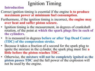
  • 1. Ignition Timing Introduction Correct ignition timing is essential if the engine is to produce maximum power at minimum fuel consumption. Furthermore, if the ignition timing is incorrect, the engine may over heat and suffer piston seizure. • Ignition timing is the measurement, in degrees of crankshaft rotation, of the point at which the spark plugs fire in each of the cylinders. • It is measured in degrees before or after Top Dead Center (TDC) of the compression stroke. • Because it takes a fraction of a second for the spark plug to ignite the mixture in the cylinder, the spark plug must fire a little before the piston reaches TDC. • Otherwise, the mixture will not be completely ignited as the piston passes TDC and the full power of the explosion will not be used by the engine.
  • 2. Introduction to ignition timing • The timing measurement is given in degrees of crankshaft rotation BEFORE the piston reaches TDC (BTDC). If the setting for the ignition timing is 10° BTDC, the spark plug must fire 10° before each piston reaches TDC. • This only holds true, however, when the engine is at idle speed. • As the engine speed increases, the pistons go faster. The spark plugs have to ignite the fuel even sooner if it is to be completely ignited when the piston reaches TDC. • To do this, distributors have various means of advancing the spark timing as the engine speed increases. • On some earlier model vehicles, this is accomplished by centrifugal weights within the distributor along with a vacuum diaphragm mounted on the side of the distributor.
  • 3. Introduction to ignition timing • Petrol engines operate on the principle of using a spark plug to ignite a compressed mixture of petrol and air in the cylinders of the engine. In practice, each spark plug fires slightly before a piston has reached the top of its compression stroke. • This is so that the petrol/air mixture has time to fully ignite before the commencement of the power stroke. • The faster that the engine is rotating, the greater is the angle before top dead centre (BTDC) that the spark plug has to fire • If the ignition timing of the engine is not correct, then either the performance or the economy of the engine will suffer, or both, and the engine exhaust will be high in hydrocarbons (HC), to a degree that might cause the vehicle to fail statutory exhaust emissions tests
  • 4. Ignition Timing Adjustment Two type of ignition timing ( static & dynamic ) Setting Static timing Static timing means setting the timing with the engine stopped. You set the crankshaft at the correct number of degrees before top dead centre, and then adjust the distributor by turning it until the contact- breaker points are just opening. Tools You Might Need  Spanners  Sockets  Circuit Tester  Screw drivers Connect one clip of the test lamp to the low-tension terminal and earth the other to the engine.
  • 5. Testing procedure • The timing mechanism in the ignition system causes the sparkplug to fire in each cylinder just before the piston reaches top dead centre (TDC) on its compression stroke. • static timing is simpler, and can be done with a circuit tester or a test lamp. • The test lamp is connected into circuit between terminal 1 of the coil or the distributor and earth. • The test takes place with the engine stopped. The crankshaft is rotated by hand in the normal direction. • The test lamp lights up when the contact breaker points open (ignition point). • If the test lamp comes on before the ignition timing point on the flywheel has reached the fixed mark on the engine block, the ignition is advanced too far; if it only comes on after the flywheel mark has passed the fixed mark, the ignition is retarded.
  • 6. Testing procedure • To retime the ignition, align the moving ignition timing mark on the flywheel or crankshaft with the fixed mark on the engine block (cylinder No.1 must be on the compression stroke). • To obtain this setting, turn the crankshaft only in its normal direction of rotation. • Strike the distributor housing gently to turn it in the opposite direction to distributor rotor rotation, until the contact breaker points open and the test light up. • In this setting, tighten the distributor firmly into position. Since the ignition timing setting could change slightly as the screws are tightened, check the setting once again by turning the crankshaft back in the opposite direction to normal rotation, then repeating the above produce. • Reset the distributor if the setting has altered.
  • 10. Timing mark A timing mark is an indicator used for setting the timing of the ignition system of an engine, typically found on the crankshaft pulley (as pictured) or the flywheel, being the largest radius rotating at crankshaft speed and therefore the place where marks at one degree intervals will be farthest apart.
  • 12. TIMING MARK MUST BE IN POSITION SHOWN NO.1 PISTON AT TDC FIRING
  • 13. Cont… • Turn until the pointer is in line with the appropriate timing mark when the piston in the timing cylinder is rising on its compression stroke. • Remember that the crankshaft turns twice for each rotation of the timing gear Other marks • If there are no numbers, the largest notch means top dead centre. • To identify the compression stroke, remove the sparkplug on the timing cylinder. Get a helper to place a finger or thumb over the hole to feel the pressure rise as you turn the engine. • An alternative way is to remove the rocker or camshaft cover and note when both valves on the timing cylinder are closed.
  • 14. Compression check • Remove the sparkplug from the timing cylinder and check with a thumb for rising air pressure as the piston comes up to TDC. • To adjust the distributor, remove the cap by undoing its clips or screws. • With the timing mark correctly aligned, the rotor arm should be opposite the contact for the timing cylinder - check by tracing back the ignition lead - and the points should be about to open. • You can confirm this by noting that the heel on the contact-breaker arm is just at the bottom of one of the cam lobes. • Remember that the cam usually turns anti-clockwise. Remove the rotor arm if it obscures the points and cam.
  • 15. Dynamic setting ignition timing  On older engines it is common to set the ignition timing using a timing light, which flashes in time with the ignition system (and hence engine rotation), so when shone on the timing marks makes them appear stationary due to the stroboscopic effect.  The ignition timing can then be adjusted to fire at the correct point in the engine's rotation, typically a few degrees before top dead centre and advancing with increasing engine speed.  The timing can be adjusted by loosening and slightly rotating the distributor in its seat.
  • 16. Dynamic setting ignition timing • If a stroboscopic (strobe) light is used, the ignition can be timed and adjusted with the engine running . • This is known as dynamic ignition timing , and eliminates all mechanical and tolerances in the distributor drive which could falsify the setting . • The individual light flashes of very short duration are controlled by the ignition spark for cylinder No. 1. • The light is directed on to fixed timing mark on the engine block and the rotating mark on the flywheel or crankshaft. • If the ignition is correctly timed, the two marks must coincide.
  • 17. Dynamic setting ignition timing • If the two marks are not opposite one another when illuminated in this way, the ignition is either advanced or retarded too far, and must be retimed by turning the distributor housing until the two marks are aligned. • This adjustment procedure is normally carried out at starting speed. • To prevent the engine from firing, either the distributor cap is removed or all the plug leads are detached except the lead to cylinder No.1. • This prevents the engine from firing and the centrifugal advance and retard mechanism from taking effect. • The vacuum hose must first be detached on engines with vacuum
  • 18. Timing light connection Procedure 1. Check distributor breaker point dwell and if necessary, adjust to manufacturer's specification. Replace breaker points if needed. 2.Disconnect vacuum hose from distributor vacuum advance unit and plug hose to insure proper operation of the carburetor. 3. Connect timing light battery leads to a 12 Volt vehicle battery; red to positive (+) and black to negative (-). 4. Connect timing light inductive pickup or clip lead to No. 1 spark plug . For best results the pickup should be hooked up with its label side facing toward the spark plug end of the wire, but placed near the distributor and away from the spark plug. This provides a "cleaner" electrical signal and keeps away from the hot manifold.
  • 19. Timing Light ; Connect red to positive (+) and black to negative & inductive pickup or Clip to no.1 spark plug.
  • 20. INITIAL TIMING CHECK 1. Start engine and adjust speed to that specified for ignition timing. 2. With timing light aimed at timing pointer, press trigger and observe position of timing mark when light flashes. Refer to manufacturer's specifications for correct setting. 3. To adjust, loosen distributor-locking screw and turn distributor until specified timing mark is lined up with pointer. 4. Tighten the distributor locking screw, and recheck timing.
  • 22. Dwell angle o The dwell angle, or cam angle, is the angle turned by the cam in the distributor from the time the points close until they open again. o The points must remain closed for a certain period of time to allow the magnetic field of the ignition coil to build up and produce a sufficiently high voltage. o The manufacturer specifies a cam angle, which can be adjusted by adjusting the contact breaker points.
  • 23. Effect of Incorrect Dwell angle Dwell angle is the amount of time (measured in degrees of distributor cam rotation) that the contact points remain closed. Initial point gap determines dwell angle. If the points are set too wide they open gradually and dwell angle (the time they remain closed) is small. This wide gap causes excessive arcing at the points and, because of this, point burning. This small dwell doesn't give the coil sufficient time to build up maximum energy and so coil output decreases.
  • 24. Effect of Incorrect Dwell angle  If the points are set too close, the dwell is increased, but the points may bounce at higher speeds and the idle becomes rough making starting harder.  The wider the point opening, the smaller the dwell.  The smaller the gap, the larger the dwell.  Adjusting the dwell by making the initial point gap setting with a feeler gauge is sufficient to get the car started but a finer adjustment should be made.  A dwell meter is needed to check the adjustment.
  • 26. Dwell angle • Connect the red lead (positive) wire of the meter to the distributor primary wire connection on the positive (+) side of the coil, and the black ground (negative) wire of the meter to a good ground on the engine. • The dwell angle may be checked either with the engine cranking or running, although the reading will be more accurate if the engine is running. • With the engine cranking, the reading will fluctuate between 0 dwell and the maximum figure for that angle.
  • 28. Is the angle of rotation of the crankshaft in which the primary circuit is closed
  • 29. o Dwell angle is affected by point or rubbing block gap Is dwell angle directly proportional to point gap or rubbing block gap?
  • 33. ADJUSTMENT  Dwell can be checked with the engine running or cranking. Decrease dwell by increasing the point gap; or increase dwell by decreasing the gap.  Dwell angle is simply the number of degrees of distributor shaft rotation during which the points stay closed.  Theoretically, if the point gap is correct, the dwell should also be correct or nearly so.  Adjustment with a dwell meter produces more exact, consistent results since it is a dynamic adjustment.  If dwell varies more than 3 degrees from idle speed to 1,750 engine rpm, the distributor is worn.
  • 42. Cont…. For a distributor with contact breaker points, the points will be just opening at the timing position. Factors affecting ignition timing Various factors affecting ignition timing are:- a)Engine load:- For less load, engine combustion is slower and hence requires more ignition advance. But with more load on the engine, faster combustion and hence lesser advance is required. b) Engine speed:- For high speed, engine needs more time for complete combustion and hence requires more ignition advance. For low speed, engine needs less time for complete combustion and hence requires lesser ignition advance.
  • 43. Cont…. c) Engine temperature:- Combustion is slower and requires more ignition advance when the engine is cold. But combustion will be faster requiring lesser ignition advance if the engine is hot. d) Cylinder bore:- Faster is the combustion and lesser the ignition advance required for smaller bore. But the combustion is slow requiring more ignition advance for larger bore. e) Compression pressure:- combustion will be slower and ignition advance is required for low compression pressure whereas, for high compression pressure the combustion is faster with lesser ignition advance required.
  • 44. Intake and fuel systems Purpose of an Intake system The purpose of an intake system is to clean the incoming air, mix it in proper proportion with fuel, vaporizing and directing the mixture into the engine cylinder. Component parts of an intake system The gasoline (carbureted) intake system consists of the air cleaner, part of a carburetor and intake manifold.
  • 45. INTAKE AND FUEL SYSTEMS Fuel filters and air cleaners Purpose of an Intake system to purify the air to captures moisture to acts as a silencer to acts as a flame arrestor Types of air cleaners pre air cleaner dry paper type oil-wetted type oil bath type cyclone type thermostatic air cleaner dry paper type
  • 46. AIR FILTER INSPECTION AND CLEANING (a) Visually check that the air filter is not excessively dirty or oily. (b) Clean the air filter with compressed air. First blow from the inside thoroughly, then blow off the outside of the air filter. If the element is torn or excessively dirty, replace it with a new one.
  • 47. ANSWER THE FOLLOWING QUESTIONS 1) what is the effect too dirty air cleaner ? 2) What is the effect of too dirty fuel filter? Dangerous Side Effects Of Dirty Air Filters here are TWO fundamental reasons to keep your air filtration system, including the cabin air filter and engine air intake filter, well preserved. 1) Waste will corrode your engine 2) Contaminants impact the fuel-air mix
  • 48. 1) Waste will corrode your engine The air filter’s main use is to clean out the bug bits, dirt, allergens and pollution from the air before it goes into the car.  Steadily, the filter becomes dirtier and dirtier until, eventually, it cannot clean the air.  When this happens, shards of debris can go through the filter and tear apart the engine.  These little contaminants wear on the engine’s metal, damaging the engine and producing more debris along the way.  If these impurities are sucked into the combustion chamber, the whole engine may fail.
  • 49. 2) Contaminants impact the fuel-air mix  When you push the gas pedal, the vehicle releases a specific amount of fuel from the tank. This fuel mixes with the oxygen running through the engine, sparking an ignition. .  When the air filter is blocked with dust and grime, airflow decreases and clean oxygen can’t mix with the fuel.  The fuel then becomes too “rich”, lowering your gas mileage and putting unnecessary stress on the engine.  Gradually, you’ll notice your car start to drive rough.  Your “check engine” light may also turn on. By disregarding the issue, you’ve set yourself up for total engine failure.
  • 50.  Keeping your air filters clean and healthy is simple!  The most essential (and easiest) part of air filtration maintenance is simply replacing the air filter.  Our ASE-certified technicians recommend an air filter inspection every 10,000-30,000 miles to make sure your car is running clean and effective. Common Signs of a Dirty Air Filter  a misfiring engine  unusual noises  reduced fuel economy  Reduced horsepower  Black sooty smoke or flames exiting the exhaust  Smell of gasoline when starting the car  Check Engine Light comes on  Air filter appears dirty
  • 51. 1) Misfiring engine Restricted air supply from a dirty air filter results in unburned fuel exiting the engine in the form of soot residue. This soot accumulates on the spark plug, which in turn cannot deliver the necessary spark to combust the air-fuel mixture. You’ll notice that the engine does not start up easily, misfires, or jerks roughly. 2) Unusual engine sounds • In normal circumstances, when your car is stationary with the engine turned on, you should sense the smooth rotation of the engine in the form of subtle vibrations. If you notice your car vibrating excessively or hear a coughing or popping sound, it is often due to a dirty or damaged spark plug resulting from a clogged air filter.
  • 52. 3. Reduced fuel economy  Your engine compensates for lower amounts of oxygen by consuming more fuel to produce sufficient power.  Thus, if you notice that your fuel economy is going down, it could be an indication that the air filter needs replacing.  Newer cars with fuel-injected engines have onboard computers which calculate the amount of air taken into the engine, and adjusts the fuel flow accordingly.  Therefore, the cleanliness of the air filter on newer cars shouldn't significantly affect fuel economy.
  • 53. 4. Check Engine Light comes on  Many modern engines suck up about 10,000 gallons of air for every single gallon of fuel burned in the combustion cycle.  Inadequate air supply can result in carbon deposits accumulating in the engine which may set off the Check Engine Light.  If that happens, have your mechanic check the air filter among other diagnostics.
  • 54. 5. Air filter appears dirty  A clan air filter appears white or off white in color, but as it accumulates dust and dirt, it will look darker in color.  However, very often, the inner layers of filter paper inside the air filter might have dust and debris that is not visible even in bright light.  Therefore, it is essential that you have your mechanic check the air filter when you take the car for maintenance.  Make sure to follow the manufacturer’s instructions regarding replacement.
  • 56. 6. Reduced horsepower • If your car does not respond adequately or if you notice jerking movements when you press the accelerator, this could indicate that your engine is not receiving all the air it needs to perform. 7. Black sooty smoke or flames exiting the exhaust • An inadequate air supply can result in some of the fuel not burning completely in the combustion cycle. • This un burnt fuel then exits the car through the exhaust pipe. If you see black smoke coming from your exhaust pipe, have your mechanic replace or clean the air filter. • You might also hear popping sounds or see a flame at the end of the exhaust. This happens when the heat in the exhaust system ignites un burnt fuel near the tailpipe. This is a potentially hazardous condition and needs to be diagnosed right away.
  • 57. 8. Smell of gasoline when starting the car  If there isn’t enough oxygen entering the carburetor or fuel ejection system when you start the car, the excess unburnt fuel exits the car through the exhaust pipe.  That’s when you’ll smell the gasoline and know that it’s time to replace the air filter.
  • 58. 2. Dirty Fuel Filter Introduction:-A fuel filter sits between your car's fuel pump and fuel injectors. • Essentially it helps screen out any impurities in the gasoline that your fuel pump may be sending toward your engine. • By acting as a barrier and removing these contaminants, the fuel filter protects your fuel injectors, your engine health, and your car's overall performance. • Since you won't always be looking directly at your fuel filter, knowing the symptoms of a dirty filter can help you can help you figure out the best way to fix your car or truck's problems.
  • 59. Signs Dirty Fuel Filter 1. Hesitating Engine 2. Stalling 3. Not Starting 4. Hard Starting 5. Different Performance at Different Speeds 1. Hesitating Engine :- If your engine keeps hesitating when you press down on the gas, you probably have a dirty fuel filter has become clogged.  A clog means the flow of gas to the engine is restricted and this abnormal combustion ultimately reduces the car's power and responsiveness.  If the car or truck doesn't respond when you accelerate or stumbles as it increases in speed, it could also be a sign of a dirty fuel filter.
  • 60. 2. Stalling  Your engine needs a constant supply of fuel if it's going to run properly and efficiently.  A fuel filter that has become dirty will constrict or narrow the flow of gas to the engine, so the vehicle supply is anything but constant.  If the flow is excessively small, the car engine will stall.  The more often this happens, the more likely it is that your truck has a dirty fuel filter that needs to be replaced. • Not Starting Since:- your engine requires a mixture of gas and air in order to fire up, it won't start at all if no gas is coming through. Failure to start is a definite sign of a dirty fuel filter or one that is completely clogged. It needs to be replaced before the vehicle will start properly.
  • 61. • Similarly, your car or truck not starting at all can also be related to a dead battery or a deteriorating ignition. If you've managed to rule those out, it's definitely time to consider the fuel filter may be the culprit. 4. Hard Starting :- your fuel filter is dirty but not completely clogged, you'll experience hard starting with your vehicle. It means that the supply of fuel to the engine is restricted so starting will become a lot more difficult. • However, be aware that a dirty fuel filter isn't necessarily the only cause of hard starting in your car. • The problem could also be in your plugs or your carburetor. Replacing the fuel filter would be a good first step toward diagnosing the problem. 5. Different Performance at Different Speeds If you have a dirty fuel filter, the gasoline that reaches your engine will have impurities and your car won't perform as efficiently.
  • 63. The Symptoms Of A Bad Fuel Filter
  • 64. Summary  Lean Air-Fuel Mixture (Cause by dirty fuel filter) :A lean air-fuel mixture contains a large amount of air. For example, 20:1 would be a very lean mixture. A slightly lean mixture is desirable for high gas mileage and low exhaust emissions.  Extra air in the cylinder ensures that all the fuel will be burned; however, too lean of a mixture can cause poor engine performance (lack of power, missing) and even engine damage.  Rich Air-Fuel Mixture (Cause by dirty Air filter) : A rich air-fuel mixture contains a little more fuel mixed with the air. For gasoline, 8:1(8 parts air to 1 part fuel) is a very rich mixture.  A slightly rich mixture tends to increase power; however, it also increases fuel consumption and exhaust emissions.  An overly rich mixture will reduce engine power, foul spark plugs, and cause incomplete burning (black smoke at engine exhaust).
  • 65.  The injection nozzle opening pressure is set to ensure that the fuel injected by the injection nozzles will mix properly with the air in the cylinder and burn.  If the nozzle opening pressure is not correct, it will effect fuel injection timing and injection volume.  The nozzle opening pressure is adjusted by changing the thickness of the adjusting shims or by adjusting the screw.  If an adjusting shim is replaced with a thicker shim, the opening pressure will become higher. If the adjusting shim is replaced with a thinner shim, the opening pressure will become lower.  Adjusting shims of several dozen thicknesses are available as supply parts for each engine.  If an adjusting screw nut is tightened the opening pressure will become higher.
  • 66. 1. NOZZLE OPENING PRESSURE TEST 1. Install the injection nozzle to the injection nozzle hand tester and bleed air from the union nut. 2. Pump the tester handle a few times as fast as possible to discharge the carbon from the injection hole. 3. Pump the tester handle slowly and observe the pressure gauge. 4. Read the pressure gauge just as the injection pressure begins to drop. – If the opening pressure is not as specified, disassemble the nozzle holder and change the adjusting shim on the top of the pressure spring.
  • 67. 2. LEAKAGE TEST  While maintaining pressure at about 10-20kg/cm2 below opening pressure (adjust by tester handle), check that there is no dripping for 10 seconds from the injection hole or around the retaining nut.  If the nozzle drips with in 10 seconds, replace or clean and overhaul the nozzle assembly.
  • 68. 3. SPRAY PATTERN TEST  The injection nozzle should shudder at a certain pumping speed between 15-60 times (old nozzle) or 30-60 times (new nozzle) per minute.  Check the spray pattern during shuddering.  If the spray pattern is not correct during shuddering, the nozzle must be replaced or cleaned.
  • 69. A. Disassemble injector nozzle (follow manufacturer procedure). B. Wash parts in clean diesel fuel.  Do not touch the nozzle mating surfaces with your fingers. C. Tilt the nozzle body about 60 degrees and pull the needle out about one third of its length. D. When released, the needle should sink down into the body vent smoothly by its own weight. E. Repeat this test, rotating the needle slightly each time. – If the needle does not sink freely, replace the nozzle assembly.
  • 70. Bleeding the Fuel System  What is bleeding ?  Why bleeding is required ?  Which automotive system may require bleeding
  • 71. Bleeding the Fuel System :Check brake system  Brake fluid level and maintain between the minimum and maximum, and used clear, undiluted fluid to refill.  Brake lines or hoses are checked and freed of twist and bends.  Hydraulic fluid if necessary without spillage and at the level specified  Brake pedal and adjust as appropriate  Brake operation including emergency brake is checked and tested.  Hydraulic fluid is changed if necessary without spillage and at the level specified Brake System Leaks  If the fluid level in the master cylinder is low, you should check the system for leaks. Check all brake lines, hoses, and wheel cylinders. Brake fluid leakage will show up as a darkened, damp area around one of the components
  • 72. Bleeding the Fuel System Bleeding air from the fuel system may well be one of the important procedures in engine maintenance  Air in the injection system may cause erratic engine performance; “missing” on one or more cylinders, reduced power, stop fuel from reaching engine and prevent or cause hard engine starting.  It must be remembered that the lift pump draws fuel from the tank, so any accumulation of air in the fuel system makes all connections, filters, etc. between fuel lift pump and tank suspect.  In any new installation one must “bleed” the system of air for, obviously, air will be in the new fuel lines, filters, etc.  If the fuel tank should run dry, bleeding will be needed when the boat is refueled
  • 73. Bleeding the Fuel System  Bleeding will also be required after changing fuel filter elements. (Time and effort may be saved if filter is charged with fuel by removing the bleed plugs on top and slowly pouring fuel into the filter until it overflows.)  Occasionally, after an extended run, an engine may slow down, or “miss”, or lose RPM or stop. Although there may be other causes, air in the fuel system should not be overlooked.  Many times a tiny leak in a fuel line fitting may allow air to enter the system and accumulate until there is sufficient to cause the above mentioned symptoms.
  • 74. Bleeding the Fuel System 1. Ascertain that there is sufficient fuel in tank, (Note: low fuel level may result in intake pipe being exposed due to “sloshing” of fuel, thus drawing air into system - try to keep your tanks topped 2. Make certain that fuel shut-off valve is turned on. 3. Loosen the bleed screw on the inlet side of the fuel filter about two or three turns. 4. Operate the priming lever at the side of the fuel lift pump on naturally aspirated unit or the pump plunger on turbocharger engines until a flow of fuel, free of air, is expelled. Then close screw.
  • 78. Brake Pedal Action  A quick and accurate way to check many of the components of the brake system is by performing a brake pedal check.  Applying the brake pedal and comparing its movement to the manufacturer's specifications does this.  The three brake pedal application distances are as follows: a) Brake Pedal Free Play is the amount of pedal movement before the beginning of brake application.  It is the difference between the "at rest" and initially applied position.  Free play is required to prevent brake drag and overheating.  If pedal free play is NOT correct, check the adjustment of the master cylinder pushrod.  If this adjustment is correct, check for a worn pedal bushing or a bad return spring, which can also increase pedal free play.
  • 79. Brake Pedal Action b) Brake Pedal Height is the distance from the pedal to the floor with the pedal at rest. • If the height is incorrect, there may be worn pedal bushings, weak return springs, or a maladjusted master cylinder pushrod. c) Brake Pedal Reserve Distance is measured from the floor to the brake pedal with the brake applied. • The average brake pedal reserve distance is 2 inches for manual brakes and 1 inch for power brakes. • If the reserve distance is incorrect, check the master cylinder pushrod adjustment.
  • 80. Brake pedal adjustment Brake pedal adjustments are made to compensate for wear of the brake shoe and may be apply brake while driving. • This involves setting the correct amount of free play in the release mechanism. – Too much free play causes a long period of time to apply brake may be this cause an accident. – Too little free play causes brake system to drag while driving which reduces vehicle speed. • A Brake pedal adjustment may be required to maintain the correct pedal height and free travel. Pedal height :-adjust the height by turning the pedal stopper bolt to the specification indicated on the manual
  • 81. FIG. BRAKE PEDAL ADJUSTMENT
  • 82. BRAKE SYSTEM BLEEDING  Brake system bleeding is the use of fluid pressure to force air from the system.  The brake system must be free of air to function properly.  Air in the system will compress, causing a springy or spongy brake pedal.  Air may enter the system any time a hydraulic component (wheel cylinder, master cylinder, hose, or brake line) is disconnected or removed.  There are two methods of bleeding brakes - manual bleeding and pressure bleeding.
  • 83. Bleeding Process : Manual Bleeding 1. Begin at the corner furthest from the driver and proceed in order toward the driver. (Right rear, left rear, right front, left front.) While the actual sequence is not critical to the bleed performance it is easy to remember the sequence as the farthest to the closest. This will also allow the system to be bled in such a way as to minimize the amount of potential cross-contamination between the new and old fluid. 2. Locate the bleeder screw at the rear of the caliper body (or drum brake wheel cylinder.) Remove the rubber cap from the bleeder screw – and don't lose it!
  • 84. Bleeding Process 3. Place the box-end wrench over the bleeder screw. An offset wrench works best – since it allows the most room for movement. 4. Place one end of the clear plastic hose over the nipple of the bleeder screw. 5. Place the other end of the hose into the disposable bottle. 6. Place the bottle for waste fluid on top of the caliper body or drum assembly. Hold the bottle with one hand and grasp the wrench with the other hand.
  • 85. Bleeding Process 7. Instruct the assistant to "apply." The assistant should pump the brake pedal three times, hold the pedal down firmly, and respond with "applied." Instruct the assistant not to release the brakes until told to do so. 8. Loosen the bleeder screw with a brief ¼ turn to release fluid into the waste line. The screw only needs to be open for one second or less. (The brake pedal will "fall" to the floor as the bleeder screw is opened. Instruct the assistant in advance not to release the brakes until instructed to do so.)
  • 86. Bleeding Process 9. Close the bleeder screw by tightening it gently. Note that one does not need to pull on the wrench with ridiculous force. Usually just a quick tug will do. 10. Instruct the assistant to "release" the brakes. Note: do NOT release the brake pedal while the bleeder screw is open, as this will suck air back into the system! 11. The assistant should respond with "released." 12. Inspect the fluid within the waste line for air bubbles
  • 87. Bleeding Process 13. Continue the bleeding process (steps 11 through 16) until air bubbles are no longer present. Be sure to check the brake fluid level in the reservoir after bleeding each wheel! Add fluid as necessary to keep the level at the MAX marking. (Typically, one repeats this process 5-10 times per wheel when doing a ‘standard' bleed.) 14. Move systematically toward the driver – right rear, left rear, right front, left front - repeating the bleeding process at each corner. Be sure to keep a watchful eye on the brake fluid reservoir! Keep it full!
  • 88. Bleeding Process 15. When all four corners have been bled, spray the bleeder screw (and any other parts that were moistened with spilled or dripped brake fluid) with brake cleaner and wipe dry with a clean rag. (Leaving the area clean and dry will make it easier to spot leaks through visual inspection later!) Try to avoid spraying the brake cleaner DIRECTLY on any parts made of rubber or plastic, as the cleaner can make these parts brittle after repeated exposure.
  • 89. Bleeding Process 16. Test the brake pedal for a firm feel. (Bleeding the brakes will not necessarily cure a "soft" or "mushy" pedal – since pad taper and compliance elsewhere within the system can contribute to a soft pedal. But the pedal should not be any worse than it was prior to the bleeding procedure!) 17. Be sure to inspect the bleeder screws and other fittings for signs of leakage. Correct as necessary. 18. Properly dispose of the used waste fluid as you would dispose of used motor oil. Important: used brake fluid should NEVER be poured back into the master cylinder reservoir!
  • 91. • Bleed one wheel cylinder at a time. Do the one farthest away from the master cylinder first and work your way to the closest. This ensures that all the air possible can be removed at the first bleeding operation
  • 92. AUTOMOTIVE ELECTRICAL SYSTEM DIAGNOSIS 1) Battery function and inspection The primary function of the battery is to provide power to operate the starting motor. It must also supply the ignition current during the starting period and accomplish this even under adverse conditions of temperature and other factors. The battery can also serve, for a limited time, as a source of current to satisfy the electrical demands of the vehicle.  Batteries used in automobiles are known as storage batteries. A battery does not store electricity but does store energy in chemical form.  It accomplishes its task by a chemical process, which takes place inside a battery when it is connected to a complete circuit. Basically, a battery is composed of two dissimilar metals in the presence of an acid. The battery is constructed of a series of positive and negative plates.
  • 93.  These plates are insulated from each other by means of separators. All the positive plates are interconnected and all the negative plates are interconnected. These interconnected series of positive and negative plates are submerged in the container filled with a sulfuric acid and water solution known as electrolyte.  i) Visual check: - the first test of a battery is visual inspection. If a battery is cracked or otherwise defective, it must be discarded.  If the electrolyte level in the battery is low, or if the ground connection or insulated connections are defective, the battery cannot operate efficiently. It is also very important that the battery be kept clean. Dirt and moisture can serve as a conductor and slowly discharge the battery over a period of time.
  • 94. FIG Batteries should be carefully checked for damage, dirt, and corrosion Battery visual checks
  • 95.  Corrosion accumulation around the cable clamps should be removed with a brush. When activating a dry-charge battery, follow the battery manufacturer’s service procedure and be sure to fill each cell properly with the electrolyte supplied.  Battery Leakage Test :to perform a battery leakage test, set a voltmeter to a low DC volt range ,Connect the negative lead to the battery’s negative post. Then move the meter’s positive lead across the top and sides of the battery case (Figure ). If some voltage is read on the meter, current is leaking out of the battery. The battery should be cleaned and then rechecked.  If voltage is again measured, the battery should be replaced; the case is porous or cracked
  • 96. Performing a battery leakage test
  • 97. Battery specific gravity test Battery specific gravity test: - By using a hydrometer, the specific gravity of the electrolyte solution in a battery can be determined. The battery specific gravity is an indication of the battery state of charge. If the state of charge is low, the hydrometer will read low. If the state of charge is high, the hydrometer will read high. As an example, a reading from 1.260 to 1.280 indicates a fully charged battery. A reading from 1.200 to 1.220 indicates a battery that is in a discharged condition and cannot give satisfactory service.
  • 98. STARTING SYSTEM SERVICE Before being to disassemble the starter motor first roughly pinpointing the source of the problem by the performance test is recommended since it helps speed up the overhaul. Also perform this test after assembly is completed to make sure that the starter motor is operating correctly. Complete each test as quickly as possible (within approximately 3-5 seconds). Other wise, the coil in the starter motor may burn out. 1. pull-in test 2. hold-in test 3 pinion return test 4 check pinion clearance 5 no-load test