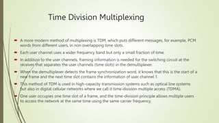
Multiplex
Dedy Wahyu Herdiyanto
Komunikasi Nirkabel RF
D4 TRE
INTRODUCTION TO MULTIPLEXING
 Multiplexing is used for the transmission of a plurality of information channels over a single
transmission medium.
 Multiplexing is a process that combines several signals for simultaneous transmission on one
transmission channel.
 An information channel may be a telephone voice channel, data channel, or a channel carrying
image information.
 There are essentially two generic methods of multiplexing information channels:
 In the frequency domain; we call this frequency division multiplex (FDM).
 In the time domain, which we call time division multiplex (TDM)
Mixing
 What frequencies may be found at the output of
the mixer?
 Both the original signals will be present, as well
as the signals representing their sum and their
difference in the frequency domain.
 Thus at the output of the illustrated mixer we
will have present the signals of frequency A, B, A
+ B, and AB.
 Such a mixing process is repeated many times in
FDM equipment.
 For example, these are 300 Hz and 3400 Hz. Let
us further consider these frequencies as simple
tones of 300 Hz and 3400 Hz.
Now consider the following mixer and examine the
possibilities at its output:
First, the output may be the sum or
A simple low-pass filter could filter out all frequencies
below 20,300 Hz.
 Now imagine that instead of two frequencies, we have a
continuous spectrum of frequencies between 300 Hz and
3400 Hz (i.e., we have the voice channel). We represent the
spectrum as a triangle:
As a result of the mixing process (translation) we have
another triangle, as follows:
When we take the sum, as we did previously, and filter out all other
frequencies, we
say we have selected the upper sideband. Therefore we have a triangle
facing to the right,
and we call this an upright or erect sideband. We can also take the
difference, such that
This is called an inverted sideband. To review, when we take the sum, we
get an erect sideband.
When we take the difference, frequencies invert and we have an inverted
sideband
represented by a triangle facing left.
Again, this modulation technique is called single-sideband suppressed carrier (SSBSC).
It is a type of amplitude modulation (AM). With conventional AM, the modulation produces
two sidebands, an upper sideband and a lower sideband, symmetrical on either side
of the carrier. Each sideband carries the information signal. If we tune to 870 kHz on the
AM dial, 870 kHz is the frequency of the RF carrier, and its sidebands fall on either side,
where each sideband is about 7.5 kHz wide. Thus a radio station on the AM dial requires
about 15 kHz of spectrum bandwidth.
Frequency Division Multiplex
 With FDM the available channel bandwidth is divided
into a number of non overlapping frequency slots.
 Each frequency slot or bandwidth segment carries a
single information-bearing signal such as a voice
channel.
 We can consider an FDM multiplexer as a frequency
translator.
 At the opposite end of the circuit, a demultiplexer
filters and translates the frequency slots back into the
original information bearing channels.
Frequency Division Multiplex Transmission
 In practice, the frequency translator
(multiplexer) uses single sideband
modulation of radio-frequency (RF) carriers.
 A different RF carrier is used for each channel
to be multiplexed.
 An RF carrier is an unmodulated RF signal of
some specified frequency.
 In theory, because it is not modulated, it has
an indefinitely small bandwidth.
 In practice, of course, it does have some
measurable bandwidth, although very narrow.
Time Division Multiplexing
 A more modern method of multiplexing is TDM, which puts different messages, for example, PCM
words from different users, in non overlapping time slots.
 Each user channel uses a wider frequency band but only a small fraction of time.
 In addition to the user channels, framing information is needed for the switching circuit at the
receiver that separates the user channels (time slots) in the demultiplexer.
 When the demultiplexer detects the frame synchronization word, it knows that this is the start of a
new frame and the next time slot contains the information of user channel 1.
 This method of TDM is used in high-capacity transmission systems such as optical line systems
but also in digital cellular networks where we call it time-division multiple access (TDMA).
 One user occupies one time slot of a frame, and the time-division principle allows multiple users
to access the network at the same time using the same carrier frequency.
Differences between FDM and FDM

Multiplex.pptx

  • 1.
  • 2.
    INTRODUCTION TO MULTIPLEXING Multiplexing is used for the transmission of a plurality of information channels over a single transmission medium.  Multiplexing is a process that combines several signals for simultaneous transmission on one transmission channel.  An information channel may be a telephone voice channel, data channel, or a channel carrying image information.  There are essentially two generic methods of multiplexing information channels:  In the frequency domain; we call this frequency division multiplex (FDM).  In the time domain, which we call time division multiplex (TDM)
  • 3.
    Mixing  What frequenciesmay be found at the output of the mixer?  Both the original signals will be present, as well as the signals representing their sum and their difference in the frequency domain.  Thus at the output of the illustrated mixer we will have present the signals of frequency A, B, A + B, and AB.  Such a mixing process is repeated many times in FDM equipment.  For example, these are 300 Hz and 3400 Hz. Let us further consider these frequencies as simple tones of 300 Hz and 3400 Hz. Now consider the following mixer and examine the possibilities at its output: First, the output may be the sum or A simple low-pass filter could filter out all frequencies below 20,300 Hz.
  • 4.
     Now imaginethat instead of two frequencies, we have a continuous spectrum of frequencies between 300 Hz and 3400 Hz (i.e., we have the voice channel). We represent the spectrum as a triangle: As a result of the mixing process (translation) we have another triangle, as follows: When we take the sum, as we did previously, and filter out all other frequencies, we say we have selected the upper sideband. Therefore we have a triangle facing to the right, and we call this an upright or erect sideband. We can also take the difference, such that This is called an inverted sideband. To review, when we take the sum, we get an erect sideband. When we take the difference, frequencies invert and we have an inverted sideband represented by a triangle facing left. Again, this modulation technique is called single-sideband suppressed carrier (SSBSC). It is a type of amplitude modulation (AM). With conventional AM, the modulation produces two sidebands, an upper sideband and a lower sideband, symmetrical on either side of the carrier. Each sideband carries the information signal. If we tune to 870 kHz on the AM dial, 870 kHz is the frequency of the RF carrier, and its sidebands fall on either side, where each sideband is about 7.5 kHz wide. Thus a radio station on the AM dial requires about 15 kHz of spectrum bandwidth.
  • 5.
    Frequency Division Multiplex With FDM the available channel bandwidth is divided into a number of non overlapping frequency slots.  Each frequency slot or bandwidth segment carries a single information-bearing signal such as a voice channel.  We can consider an FDM multiplexer as a frequency translator.  At the opposite end of the circuit, a demultiplexer filters and translates the frequency slots back into the original information bearing channels.
  • 6.
    Frequency Division MultiplexTransmission  In practice, the frequency translator (multiplexer) uses single sideband modulation of radio-frequency (RF) carriers.  A different RF carrier is used for each channel to be multiplexed.  An RF carrier is an unmodulated RF signal of some specified frequency.  In theory, because it is not modulated, it has an indefinitely small bandwidth.  In practice, of course, it does have some measurable bandwidth, although very narrow.
  • 7.
    Time Division Multiplexing A more modern method of multiplexing is TDM, which puts different messages, for example, PCM words from different users, in non overlapping time slots.  Each user channel uses a wider frequency band but only a small fraction of time.  In addition to the user channels, framing information is needed for the switching circuit at the receiver that separates the user channels (time slots) in the demultiplexer.  When the demultiplexer detects the frame synchronization word, it knows that this is the start of a new frame and the next time slot contains the information of user channel 1.  This method of TDM is used in high-capacity transmission systems such as optical line systems but also in digital cellular networks where we call it time-division multiple access (TDMA).  One user occupies one time slot of a frame, and the time-division principle allows multiple users to access the network at the same time using the same carrier frequency.
  • 8.