1. Abstract— This project describes about the implementation of
redesign the MY DEAR baby stroller (18007) by using the
application of Boothroyd Dewhurst, Design for Manufacturing
and Assembly (DFMA) methodology. The scope based on the
existing baby stroller and the appropriate of DFMA
methodology. The main focus is to reduce the part count, the
assembly time and cost and ease of manufacturing. The tools of
DFMA: Design for Assembly (DFA) and Design for
Manufacturing (DFM) are going to be applying in this project.
DFA method is applied on baby stroller to reduce assembly time
and cost and generate the design efficiency of the baby stroller.
The methodologies are followed in order to analyze the each
parts of the product to determine design efficiency. Then the
product will undergo redesigning process. The new design will
undergo same process as above to determine the new design
efficiency. Afterward, redesigned parts will undergo DFM
method in order to select proper material and process. From the
study, it was found that the design efficiency increases from 14%
to 18% when Boothroyd Dewhurst theory was applied. The time
of assemble also decreased from 1345s to 883.3s per product.
From the result, it was proven that this DFMA method was able
to improve the design in terms of design efficiency, product
assemble time and operation cost.
Index Terms— DFMA, Boothroyd Dewhurst, Baby Stroller
I. INTRODUCTION
HIS DFM and DFA are developed in the early 1970‟s by
Dr Geoffrey Boothroyd and Dr Peter Dewhurst. Then,
they created and developed the DFMA, Design for
Manufacturing and Assembly (Xie X, 2006). Design for
Manufacturing, DFM is the method of design for ease of
manufacturing of the collection of parts that will form the
product after assembly. Design for Assembly, DFA is the
method of design of the product for ease of assembly.
(Stienstra D et al, 2001)
A baby stroller has been selected as a case study for this
project. This project is going to be developing under Design
Daniel S/O Pragasom undertook Diploma in Mechanical Engineering at
University Selangor in 2009 and graduated in year 2012. He then went on to
obtain his bachelor in mechnanical engineering in year 2012 at the same
university and graduated honorably in year 2015. Daniel is with Institution of
Engineers Malaysia, as on October 2015 onwards.
for Manufacturing and Assembly (DFMA) technique. The
main focus is to reduce the part count in baby stroller and the
assembly time. The tools of DFMA: Design for Assembly
(DFA) and Design for Manufacturing (DFM) are going to be
applying in this project. The first stage of this project is to
apply the DFA technique on baby stroller to reduce part count
and assembly time and at same time finding the manual
assembly efficiency of the baby stroller. The second stage is
the implement of DFM technique on baby stroller. The
software going to be used for drawing is CATIA V5R16.
The objectives of this project are:
i. To meets the manufacturers need to reduce cost and time.
ii. To simplify current design of Baby Stroller in order to
improve the manufacturing and assembly process.
iii. To minimize parts counts.
There are several significances in this project, they are
firstly come up with a new simplified design where the time
and cost reduced and at the same time efficiency is higher.
Secondly, the assembly costs will be lower by using fewer
parts, eliminating certain parts wherever possible and reduce
the manpower required for assembly. Thirdly, reliability
increases by lowering the number of parts, thus decreasing the
chance of failure. Lastly, total time to market is shorter since
products developed using DFMA. There are few indirect
significances of this project; firstly, manufacturing company
will gain financial benefit. Furthermore, the working
environment becomes more pleasant and safe to the workers.
In addition, the ergonomics in the working environment
improved by reduce stress, eliminate injuries and disorders
associated with the overuse of muscles, bad posture and
repeated tasks.
II. LITERITURE REVIEW
1. Introduction
Boothroyd et al mentioned that in order to overcome
complication during manufacturing process, the engineers
have to consult with the designers. The action of consulting
and discussing is known as simultaneous engineering.
Simultaneous engineering or also known as concurrent
engineering is vital in preventing many problems.
Winner et al has stated that concurrent engineering or
simultaneous engineering is a systematic approach to the
integrated, concurrent design of products and their related
processes, including manufacture and support. This approach
is to cause the developers to consider all elements of the
DESIGN FOR MANUFACTURING AND
ASSEMBLY FOR BABY STROLLER (18007)
Daniel S/0 Pragasom, Bachelor Mechanical (Hons) Engineering, University Selangor
T
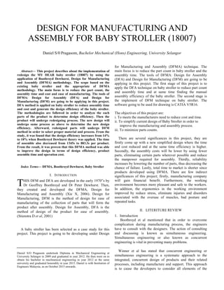
2. Time-to-market
improvements
39%
Improvements
in quality and
reliability
22%
Reduction in
manufacturing
cycle time
17%
Reduction in
assembly time
13%
Reduction in
part
counts/costs
9%
product life cycle which includes quality, cost, schedule, and
customer requirements and disposal. Furthermore, the main
objective of this concurrent engineering is to achieve
improved product development performance.
O’Grady et al said that Design For X (DFX) is actually
design decision support tool, such as Design for Assembly,
Design for Manufacture, Design for Environment, Design for
Disassembly, Design for Service, or Design for Six. These
design decision support tools are consider as importance
manufacturing and assembly processes of a product lifecycle.
This tools leads to benefits in increased reliability, quality,
shorter manufacturing time and overall efficiency in the
assembly process, which is responsible for more than 50% of
total manufacturing cost and 40% to 60% of total production
time.
Hermnann et al mentioned that DFX tools recognize design
considerations occurring throughout a product development
cycle, for instance manufacturing, assembly, quality,
production, and environmental impact.
Michel, K discussed that DFX tool is used for the design of
manufacturing and assembly it descript as Design for
Manufacturing (DFM) and Design for Assembly (DFA)
respectively. DFM and DFA is the most common DFX tools
as they allow better assessment to the manufacturing
industries.
Xie X thought that DFM is actually begins before the
Second World War, where the FORD and CHRYSLER was
used the DFM philosophy to design and manufacture their
weapons, tanks and other military equipment. DFM and DFA
are commencing in the early 1970’s. Dr Geoffrey Boothroyd
and Dr Peter Dewhurst are researcher of this technologies
Curtis, M.S proved that it was possible to measure the
efficiency and cost of various assembly and manufacturing
processes through their research. Boothroyd and Dewhurst
were able to develop a wide-ranging database that is now
available as a software toolkit or in traditional handbook form.
2. Advantages of DFMA
Figure 1: Survey on importance of reductions produced by
DFMA. (Reader poll, Computer-Aided Engineering, 1993)
DFMA cut down assembly time by using of standard
assemblies such as vertical assembly and self-aligning parts.
DFMA also enhance the reliability by minimize the number of
parts, as a result decreasing the chance of failure. As products
developed using DFMA, the products make the fastest and
smooth move into the production phase; the time for a product
to reach the consumer is reduced. (Boothroyd, G, et al 2002)
3. Designs for assembly (DFA)
Design for Assembly (DFA) is introduced by Boothroyd-
Dewhurst (USA), Lucas-Hull (UK) and Hitachi (Japan). All of
these three have been used in industry. Among these three
methods, Boothroyd-Dewhurst is the most widely used.
Design for Assembly (DFA) is describe as an approach to
reduce the cost and time of assembly by simplifying the
product. In the original design, assembly is done by using the
common fasteners and then it undergoes DFA method, the
product become as one-piece base with elimination of
fasteners. At the final stage of design using the DFA, the
product become more efficient in assembly by applies just a
push and snap assembly which is really easy to assemble.
3. Design for manufacturing (DFM)
The term of Design for Manufacturing (DFM) according to
(Boothroyd G et al, 2002), is a method used for ease the
manufacturing process of a product. The goal of DFM is to
design a product which can simply and economically
manufacture. DFM adapt the products design to
manufacturing conditions in order to make the manufacturing
process more efficient. At the same time DFM also
minimizing the production cost and time of the product to
market and also maintain the quality of the product
III. METHODLOGY
1. DFA objectives
The primary objective of DFA is to minimize part counts.
This leads to fewer parts that must be manufactured and
assembled, fewer parts that can fail, and fewer interfaces
between parts. DFA's second objective is to have remaining
parts of a nature that they are easily assembled together. These
objectives lead to the primary expected DFA results for the
assembly: (Tatikonda M. V, 1994)
i. Reduced material cost
ii. Reduced labor and/or automatic assembly cost
iii. Reduced assembly cycle times
iv. Higher product quality and reliability.
3. 2. Flow Chart
3. Product to be studied
Figure 2: MY DEAR Baby stroller 18007
4. Disassemble product parts
Figure 2 shows the baby stroller 18007. The parts are
having been disassembled and labeled.
5. Identification of part functions
To improve the product, the information about the product
and its assembly is important. To collect the information
correctly, the each and every part of the product need to be
disassemble. The disassembling process is done in Workshop
Mechanical 1 in UNISEL. The grinder is used to disassemble
all the parts because the parts are fixed with the rivets. The
rivets used for this assembly are solid rivets. After the parts
are disassembled, it will undergo a process to obtaining the
dimensions of each part. The dimensions are obtained by
using the rulers and measuring tape. Then the function of each
part is needed to be defined. To know the complexity of the
part, the part should be viewed in 3D. Afterward, each parts is
need to define the axis of symmetry in degree (α + β) to
identify the relative motion of assemble. The collected details
are tabulated and referred as the part critique. Then, form
Product Tree Structure to identify the sub-assemblies of the
product.
Table 1: Example of Part Critique
Figure 3: Product tree structure (PTS)
6. DFA worksheet
In this stage, a table is generated and referred as the
Classification of Each Part for Original Design (DFA
worksheet) .This table is actually to find the assembly time,
assembly cost and assembly efficiency.
Part
No.
Part
Name
Function Material Size(mm) Rotational
SymmetryThickness Length
1 Front
Wheel
Easy to move,
provide mobility
Plastic 25 150 α – 360 +
β – 360
2 Front
Wheel
pin
To hold the wheel
with the body.
Steel 8 101 α – 360 +
β – 0
3 Swive
l axle
Provides 360-
degree of freedom
for front wheels
Plastic 15 122 α – 360+
β – 360
Start
Title Selection and Proposal
Study and research journals, books and articles
Literature Review
Analyze the design of the product
Redesign the product and DFA analysis
Result
Report Writing
End
Calculate and measure the
improvise parts are efficient for
production benefit
DFM analysis
If efficiency low
Sub Assembly 2
(Main body upper beam)
Sub Assembly 1
(Main body rear bottom beam)
Sub Sub
Assembl
y
Front and
rear bottom
beam
connector
Sub Sub
Assembly
Main body
front bottom
beam
Sub Sub
Assembly
Sub Sub
Assembly
Sub Sub
Assembly
Holder
rod of
tray
Back wheel
holder
with body
Seat
Basement
Product Tree Structure of ‘Baby Stroller’
4. Table 2: Example Classification of Each Part for Original
Design (DFA worksheet)
Then, the theoretical minimum number of parts needs to be
estimate and tabulate. The theoretical minimum number of
parts represents a situation where separate parts are combined
into a single part unless, as each part is added to the assembly,
one of the following criteria is met.
Table 3: Example of theoretical minimum number of parts
7. Analysis
From the information gathered the assembly design
efficiency can be calculated by using the formula:
Design Efficiency = (3 ×NM) ÷TM
NM: Theoretical minimum number of parts
TM: Total manual assembly time
8. Propose for improvement
The improvement must be done for assembly design
efficiency by reducing part count by combining or eliminating
certain parts of the product. Possibilities of eliminate the
unnecessary parts by applying the theoretical minimum
number of parts. Major improvement and minor improvement
must be done by identify the highest assembly time.
(Boothroyd, G, 2002). After the reduction of part count, the
product will undergo redesign. After the redesign, the new
products will undergo same process as above to determine the
assembly design efficiency.
9. DFM methodology
Design for Manufacturing can reduce many costs, as the
products can be quickly assembled. Therefore, products are
easier to assemble, in fewer times and with better quality.
DFM process can be classified into three stages such as define,
analyze and justify. In the every stages of the DFM process,
there is a problem solving method on methodology. The three
stages briefly discussed below.
i. Define
In this stage, DFM analysis starts with the first step
which is part selection from the product after
improvement. There are seven improvement parts
which can select to perform DFM analysis.
The parts specification is prepared in order to define
the seven selected parts.
ii. Analyze
In this stage material and process selection method will
be carried out. In order to select the proper material and
process, the shape geometry of the part also known as
the 8 shape attributes must be identify. Shape attributes
is the consideration of size, shape, and cross-section of
the part. Afterward, the selection of process used to
manufacture the part can be done by using the pattern-
matching rules. The proper materials to produce the
part can be select by based on the theory of materials
selection
iii. Justification
As the final stage, the elimination process will be
carried out, as a result it will show the remaining
process which can be used to manufacture parts. The
process will be selected based on the material, cost and
amount of production of the part.
IV. RESULT
1. The Original Design
The descriptions of the original design of the product have
been already shown in previous Chapter 3. This chapter will
be discussing about the details descriptions of the original
product parts and the function of each product.
2. Efficiency of the original design
By using Design Efficiency formula as discussed in Chapter 2
the efficiency of original design is calculated:
Design Efficiency = (3 ×NM) ÷TM
= (3 ×63) ÷1345
=14 %
NM= theoretical minimum number of parts
TM= total time manual assembly parts
Estimated theoretical value of assembly time = 1800 seconds
3. Description of Part Improvements
Table below (Table 4) shows the parts which are
undergoing the improvement process.
Table 4: Example of Part Improvement Description
C1 C2 C3 C4 C5 C6 C7 C8 C9 C10
Nameofpart
Partidnumber
Nooftimestheoperation
iscarriedout
i
Two-digitmanual
handling
Manualhandlingtime
perpart
Two-digitmanual
insertioncode
Manualinsertiontime
perpart
Operationtime(sec)
(2)x[(4)+(6)]
Operationcost(cents)
[0.0011(MAS)x7]
Estimationoftheoretical
minimumnumberofpart
Front Wheel 1 4 30 1.95 06 5.5 29.8 0.03576 1
Front wheel pin 2 2 10 1.5 35 7 17 0.0204 1
Swivel axle 3 2 30 1.95 06 5.5 14.9 0.01788 1
Rear Wheel 4 4 30 1.95 О6 5.5 29.8 0.03576 1
Name of part Description Theoretical minimum parts assessment
Relative
Motion
Different materials Separate for
assembly
●Front wheel
●Front wheel
pin
●Swivel axle
●Front wheel
holder with
body
●Pin 1
By using a bigger size
wheel and a basic
design of the swivel
axle, the two front
wheel and old swivel
axle can be eliminate.
Yes
Yes
Yes
No
No
Yes
Yes
Yes
Yes
No
Yes
Yes
Yes
Yes
Yes
5. Example of Part Improvement: Front Wheel
Category: Major improvement
Reduce time: 31.2 sec
Justification: A bigger size wheel and a basic design of the
swivel axle replaced with the two front wheel and old swivel
axle where it can improve the assembly time and
manufacturing cost.
4. Efficiency of the new design
By following the same step as mentioned in Chapter 3, new
part critique, new product tree structure, new DFA worksheet,
new theoretical minimum number of parts are prepared for
new design. Finally, by using Design Efficiency formula as
discussed in Chapter 2 the efficiency of new design is
calculated:
Design Efficiency = (3 ×NM) ÷TM
= (3 ×51) ÷843
=18 %
NM= theoretical minimum number of parts
TM= total time manual assembly parts
Estimated theoretical value of assembly time = 1200 seconds
5. New Design Description and Drawing
New design of the product is designed by using the
CATIA software as shown in Figure below.
Figure 3: Assemble drawing for new design
6. Design for manufacturing (DFM)
The improved parts are going to be analyzed for DFM
process except the main seat because the main seat
manufactured by the Fabric manufacturers.
Table 5: Example of selected DFM parts specification
7. DFM Process
As mentioned in Chapter 3, DFM process can be classify
into three stages such as define, analyze and justify. Each part
is defined by its name, analyzed based on shape attributes and
process elimination based on eight geometric attributes.
Finally it will be justified according to the data to choose the
proper process.
Parts
Id No
Name of
Part
Operation
Time (sec)
α+β
1 Front
wheel
29.8 720
2 Front
wheel
holding
pin
17 360
3 Swivel
axle
14.9 720
7 Front
wheel
holder
with body
17.9 720
62 Pin 1 35.8 720
Total time 115.4
Parts
Id No
Name of Part Operation
Time (sec)
α+β
07 Front wheel 6.9 720
09 Front wheel
pin
17 360
3 Swivel axle 6.9 720
7 Front wheel
holder with
body
17.9 720
62 Pin 1 35.8 720
Total time 84.2
No Part
ID
No.
Part Specification
1. 07
&
08 Part name:
Wheel spoke.
Dimension: Øin = 140mm;
Øout =159mm
Thickness: 40mm
Material:
Thermoplastic or Thermosets
Function: To provide mobility
and easy to move.
Before After
6. 8. Comparison of New Design and Old Design
Table 6 shows the data comparison between the original
and new design. The comparison is done in order to obtain the
percentage change from the original and new design.
Table 6: Comparison Quantitative value for new design and
old design
Figure below (Figure 4) shows the bar chart of percentage
change.
Figure 4: Percentage change Bar Chart
9. Discussion
The DFMA analyses have confirmed that improved
designs are much effective than the original design by
referring the Table 6 and Figure 4. The total product assembly
time is 1345 sec (22.4 min) and total operation cost is RM
1.479. The efficiency of the original design is 14%. The
product tree structure consist four levels of assemblies. From
this analysis data, the product is able to improve and redesign
in order to improve its efficiency and performance. By
redesigning the product, the original efficiency, product
assembly time and operation cost will improve. Once the
product is redesigned by using similar methods as original
design, the total assembly time of new design is 883.3 sec and
operation cost is RM 0.929. The efficiency of new design
improved up to 18%. Still the product tree structure consist
four levels of assemblies but total number of parts has reduced
without changing the product’s function and new design parts
are introduced which are simplify the process of assembly.
Once the DFA process is completely done, the new design
will undergo DFM process in order to reduce the cost of
manufacturing. By implementing DFM process, MY DEAR
Company able to improve fabrication process and minimize
the cost.
The DFM process can be done by referring the guidelines
as discussed in Chapter 2. By the way, the selection of the
manufacturing process will be determined by the elimination
of processes based on the characteristics of the parts and the
materials properties of the part. From the analysis, it is
necessary to select the process according to the characteristic
of product parts. Most of the baby stroller’s parts are plastic
material which can easy produce by one single process which
can lead to reduction of manufacturing cost.
V. CONCLUSIONS AND RECOMMENDATIONS
1. Recommendations
Through this research, MY DEAR Company is
recommended to implement the DFMA techniques in their
products in order to increase their productivity, reduce
manufacturing and assembly cost and time and enhance the
demand from customer. MY DEAR is one of the leading
companies for baby care product. Application of DFMA on
MY DEAR Company will lead to produce their product with
unique design by simplifying the parts. Consequently, the
assembly time and labor cost will reduce. In addition, product
development process will improve. As result MY DEAR can
sustain its place and become fore-runners in the market.
Among the other method, Boothroyd and Dewhurst
DFMA method mostly recommended. Boothroyd and
Dewhurst created and developed the DFMA concept which is
used in developing the products of their company (DFMA
software system). The Boothroyd-Dewhurst methods provide
a quantitative measure known as the design efficiency based
on analysis of a product. (Boothroyd. G, 1987). Moreover,
Boothroyd and Dewhurst DFMA method doesn’t demand for
higher design efficiency for improved product
Further improvement can carried out on the product if
more time is provided. Further improvement includes reducing
the number fasteners (rivet) or replacing new type of fastener
and some design improvement. By reducing the number of
fastener, the efficiency of product will improve. Possibly in
future the fasteners (rivet) are able to replace with other
fastener to improve the assembly time and design efficiency as
well.
2. Conclusion
DFMA is successfully applied on MY DEAR baby stroller
18007. The three objectives of the study were achieved.
DFMA analysis has reduced the operation cost and assembly
time of product. The total operation cost of new design has
reduced from RM 1.479 to RM 0.929 and the percentage
change is 37.19%. Meanwhile, the total assembly time also
reduced from 1345 seconds to 883.3 seconds and the
percentage change is 34.32%. The design efficiency has
improved from 14% to 18% after the successful DFMA
analysis. The increment of efficiency is only 4% and it’s
acceptable in Boothroyd and Dewhurst DFMA method as
mentioned in recommendation. The efficiency can be
improved if the product is undergoing further improvement by
using same DFMA method.
-40.00%
-20.00%
0.00%
20.00%
% change
Total Part
Unique Part
Total Operation Cost
(RM)
Total Assembly Time
(second)
Design Efficiency (%)
Original Design Improved Design % change
Total Part 167 127 23.95%
(decrease)
Unique Part 69 52 24.63%
(decrease)
Total Operation
Cost (RM)
1.479 0.929 37.19%
(decrease)
Total Assembly
Time (second)
1345 883.3 34.32%
(decrease)
Design Efficiency
(%)
14% 18% 4% (increase)
7. REFERENCES
Boothroyd, G. (1980). Design Project: Design for Assembly
Handbook. Amherst, United States: University of
Massachusetts
Boothroyd, G., (2010). DFMA Design For Manufactuirng
and assembly. Executive White Paper: Design for
Manufacture & Assembly Reduce Costs Increase Profit.
Page 5 of 28
Boothroyd, G (1987). International Journal: Advanced
Manufacturing Technology, Bedford. U.K: IFS
Publications Ltd.
Boothroyd G, Peter Dewhurst and Winston Knight (2002).
Product design for manufacturing and assembly. (2nd
ed).
Switzerland: Marcel Dekker AG. Curtis, M.S, (1992)
Product Development. Boothroyd Dewhurst's DFMA(R)
and JCB excavators’ New York City: The Institute of
Electrical and Electronics Engineers.
Herrmann, J. W., Cooper, J., Gupta, S. K., Hayes, C. C., Ishii,
K., Kazmer, D., Sandborn, P. A. & Wood, W. H. (2004)
Proceedings of the ASME Design Engineering
Technical Conferences and Computers and Information
in Engineering Conference. New directions in design for
manufacturing. United States: University of Utah.
Michel, K., Tezera Wodajo (2012). Application of a Design
Method for Manufacture and Assembly. Flexible
Assembly Methods and their Evaluation for the
Construction of Bridges. Sweden: Chalmers University Of
Technology. Retrieved from
http://publications.lib.chalmers.se/records/fulltext/164233
O'Grady and Wu, (1999) A Concurrent Design Method Based
on DFMA-FEA Integrated Approach. Catania, Italy:
University of Catania. Retrieved from
http://cer.sagepub.com/content/17/3/183.abstract
Reader poll (1993). Computer Aided Engineering. Survey on
importance of reductions produced by DFMA.
Stienstra, D. (n.d.). Introduction to Design for (Cost
Effective) Assembly and Manufacturing.
Tatikonda, M. V. (1994). Production and Inventory
Management Journal: Design- For-Assembly: A
Critical Methodology for Product Reengineering and New
Product Development. Chapel Hill, Carolina: University
of North Carolina.
Winner, Robert, I., Pennell, James, P., Bertrand,
Harold E., and Slusarczuk, Marko M. G. (1991). The Role
of Concurrent Engineering in Weapons System
Acquisition. Alexandria, Virginia: Institute for Defense
Analysis.
Xie, X. (2006). Design for Manufacture and Assembly. United
States: University of Utah. Retrieved
fromhttp://www.cc.utah.edu/~u0324774/pdf/DFMA.pdf