1. 1
FACULTY OF ENGINEERING AND APPLIED SCIENCE
ENGR3930U-HEAT TRANSFER
DESIGN PROJECT REPORT
Improving Home Insulation and Reducing Energy
Consumption
Instructors: Prof. Dr. Ibrahim Dincer
TA: Rami El-Emam
LAB GROUP No.
Date
performed
Date
Submitted
Date
received
No.
of pages
Grade
LAB GROUP MEMBERS
Surname Name Signature ID
1 Tuan Nguyen 100344743
2 Daniel Bondarenko 100363648
Remarks:
• If one in group cheats, the entire group will be responsible for it.
• Plagiarism and dishonesty will not be tolerated.
• The group member(s), who don’t sign the report, will be considered “not contributed” and given “zero” for the report.
• This cover sheet should be fully completed.
• All reports should be submitted in two weeks time to the TAs during the lab session.
2
2. 2
Table of Contents
Page #
Summary…………………………………………………………………………………………………………………………………………… 3
Introduction……………………………………………………………………………………………………………………………………… 3
Theory………………………………………………………………………………………………………………………………………………… 4
Energy Saving Tips and Government Subsidy Information………………………………………………………4
Weather Information For Oshawa…………………………………………………………………………………………………5
Air Properties For Weather Data………………………………………………………………………………………………… 6
Basement Floor Plan and Analysis……………………………………………………………………………………………………7
Basement Floor Optimization…………………………………………………………………………………………………………12
1st
Floor Plan and Analysis……………………………………………………………………………………………………………… 16
1st
Floor Optimization………………………………………………………………………………………………………………………34
2nd
Floor Plan and Analysis…………………………………………………………………………………………………………… 38
2nd
Floor Optimization…………………………………………………………………………………………………………………… 48
Conclusion………………………………………………………………………………………………………………………………………… 50
References……………………………………………………………………………………………………………………………………… 50
3. 3
SUMMARY
Essentially, this lab report contains our attempts and results in reducing the total energy
losses within a house by at least 25 percent. Initially, we decided to map out a floor plan for a 2
storey approximately 3000 square foot house. Afterwards, we decided to calculate the energy
and heat losses for the house in its initial state without any improvements. Afterwards, we
decided to redesign the windows and insulation and recalculate the energy losses to see if the
minimum improvement objective of 25 percent was accomplished. Once that was completed,
we decided to look for various government subsidies that were provided by the Canadian
Government, if one choose to make improvements towards their house based on our design and
specifications.
INTRODUCTION
The purpose of our Heat Transfer design project was to reduce the average energy
consumption of an average house by at least 25 percent. This was done by redesigning various
sections of the house so that there could be less heat transfer losses, which in turn would
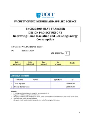
reduce the amount of energy needed to cool/heat the house. According to Natural Resources
Canada, it was shown statistically that Ontarians living in a single detached house consume
roughly 118.7 PJ (peta joule) and 252.5 PJ of electricity and gas in a year, respectively.
Therefore, it was important for us to accomplish the objective of the project because not only
would it save money, but it would also improve the environment by lowering the carbon
footprint and green house gases of the average Canadian. Also, by using the recycled materials
such as mineral fiber insulation and environmentally friendly plastics like PLA, the carbon
footprint would be reduced not only in energy consumption but also by the damage caused by
unused or disposed building materials.
Figure 1: Table from Natural Resources Canada showing the annual energy consumption of
single detached houses within Ontario.
4. 4
THEORY
In regards to the theory of our design project, it can be said that it was mostly based on
thermal conductivity. This is because since we were designing the house to minimize heat loss,
it can be said that selection of material to insulate the house was of utter most importance.
Therefore thermal conductivity played a majored role in our design because it is one of the
most important properties of a material that determines how much heat the material is able to
conduct/insulate. As such, it can be said that materials with a high thermal conductivity are
good heat conductors and materials of low thermal conductivity are good insulators. However,
in regards to our project, we mostly selected material of low thermal conductivity because we
were looking for good insulators that minimized heat loss.
We also used the theory of thermal resistance network for the walls and insulations of
the house. This is because the walls of our house consists of many layers being the brick and
motor, then the wood and insulation, then the plywood, and lastly the dry wall. Therefore, the
theory of thermal resistance network was vital towards our project because it was mainly used
to see the heat transfer losses that occur through the layers of the wall for our house.
In order to choose the proper temperature for the analysis the gas and energy bills were
found highest during the month of January for winter period, with a gas bill valuing at $235.75
per month. It was further found what date had the lowest temperature and how low was it.
ENERGY SAVING TIPS AND GOVERNMENT SUBSIDY INFORMATION
If one decided that the improvements to reduce energy use and heat transfer losses by our
method and design were too expensive or not practical, then here are some energy saving tips
that are more cost effective and practical that can be used as an alternative.
Try setting the thermostat at 20 degrees Celsius during the day and 17 degrees Celsius
during the night. Lowering a house’s temperature regularly during the night for 8 hours
a day can reduce gas usage by 6%.
Install your thermostat in an air neutral zone. This will inhibit your furnace from
running too often due to drafts or etc.
During cold months, windows will lose a significant amount of heat. Therefore, try to
seal cracks and drafts with caulking or any alternative method to reduce the loss
Check your attic, make sure there is enough insulation and that the attic is well vented
towards the outdoors.
If one were to redesign their homes based on our design and specification, then there are some
subsidies provided by the Ontarian Government that will help financially. There is a list below
of various rebates and incentives provided by the Ontario Government.
- Ontario home owners can get rebates for various insulations improvement from the
following:
• Attic or roof insulation rebate of up to $750.00
• Exterior Wall Insulation of up to $1875.00
• Windows and Doors rebate of $40.00 dollars for each replacement unit
5. 5
- Ontario home owners can get a Eco Energy Home Retrofit Grant of up to $5000.00 if
they do the following:
I. Have an accredited energy advisor do an energy evaluation on your home
II. Do your home improvements
III. Have your advisor do another energy evaluation to see how much more energy
efficient your house is
IV. The advisor will send your final evaluation to Natural Resources Canada, who
will then send you a rebate check
Weather Data for the Coldest Day in January for Oshawa, Ontario [1]
6. 6
Minimum Temperature of the Day Data (Considering the wind speed effects on the heat transfer
coefficient)
Tout= -24.0 [o
C]
Dew Point Temperature = -26.5 [o
C]
Relative Humidity = 80%
Wind direction 20 degrees from North
Wind Speed =11[km/h]=3.056[m/s]
Pressure = 101[kPa]
Air Properties (Found in Table A-15):
Coldest Day:
T = -24[o
C]
Vwind=11[km/h]=3.056[m/s]
ρ=[1.451+(1.394-1.451)*(-24+30)/(-20+30)][kg/m3
]=1.4168[kg/m3
]
k=[0.02134+(0.02211-0.02134)*(-24+30)/(-20+30)][W/mK]=0.021802[W/mK]
α=[1.465/105
+(1.578-1.465)/105
*(-24+30)/(-20+30)][m2
/s2
]=1.5328/105
[m2
/s2
]
μ=[1.579/105
+(1.630-1.579)/105
*(-24+30)/(-20+30)][kg/ms]=1.6096/105
[kg/ms]
ν=[1.087/105
+(1.169-1.087)/105
*(-24+30)/(-20+30)][m2
/s]=1.1362/105
[m2
/s]
Pr=[0.7425+(0.7408-0.7425)*(-24+30)/(-20+30)]=0.74148
Hottest Day:
T = 34[o
C]
Vwind=21[km/h]=7.222[m/s]
ρ=[1.164+(1.145-1.164)*(34-30)/(35-30)][kg/m3
]=1.1488[kg/m3
]
k=[0.02588+(0.02625-0.02588)*(34-30)/(35-30)][W/mK]=0.026176[W/mK]
α=[2.208/105
+(2.277-2.208)/105
*(34-30)/(35-30)][m2
/s2
]=2,2632/105
[m2
/s2
]
μ=[1.872/105
+(1.895-1.872)/105
*(34-30)/(35-30)][kg/ms]=1.8904/105
[kg/ms]
ν=[1.608/105
+(1.655-1.608)/105
*(34-30)/(35-30)][m2
/s]=1.6456/105
[m2
/s]
Pr=[0.7282+(0.7268-0.7282)* (34-30)/(35-30)]=0.72708
7. 7
Basement Floor Plan
Basement Window Sill-Box Dimensions
Width [m] Height [m] Length [m]
Window 1 0.79 0.36 0.46
Window 2 0.79 0.26 0.52
Window Parameters:
Double-Pane, Double Glazing, one side Low-e Coated Windows, air filled, tightly sealed, vinyl framed,
with metal spacer type.
Thickness of space inside the window Δxair=0.010[m];
Thickness of the acrylic of the window Δxw=0.0025[m]; kacrylic= kacr=0.19[W/(mK)] (From the ending
article of chapter 9)
Frame thickness Δxw=0.041[m]
The basement wall is solidly composed of bricks and rocks, the approximate coefficient of conduction
for this composite is chosen from Table A5 to be equivalent to the coefficient of conduction of dense
fired clay bricks or kbasement wall= kbw= 1.34[W/(mK)]. The basement floor is concrete and from Table A5
can be approximated by the value kconcrete= kconc= 1.1[W/(mK)]
8. 8
Basement Heat Loss Analysis
Frost Penetration depth is about 1.2[m] deep in the area of Oshawa, that is at the depth of 1.2[m] the
soil temperature is 0[o
C]. [2]
Note: The basement outer wall temperature is in contact with soil. The basement does not have air
conditioning nor is it heated. Basement windows are blocked from wind interaction by a concrete
barrier and a non-insulating transparency.
Assumptions:
Steady state conditions are applicable under extreme conditions (i.e. the coldest and the hottest
temperatures) in order for the optimization process to yield stable results regardless of transient effects
spanning over a year. That is the analysis of heat conduction of a given house considers peace time
conditions and no immediate threat, such as local power station anomaly, or extreme weather such as
hurricane.
Assume ideal and incompressible gas conditions.
The soil is dry and compact in the vicinity of the basement which allows for soil heat conduction
coefficient to be ksoil=0.5[W/(Km)].
The surface temperature of soil is the same as the air temperature on either the hottest or the coldest day
due to applied steady state conditions.
Take a 100X100[m2
] patch of land to approximate for heat losses from the ground to the atmosphere at
a given penetration depth
The average temperature of outer basement wall:
For winter:
Tsoil surface= Tss = -24[o
C], Tfrost penetration depth= Tfpd = 0[o
C]
dx=1.2[m], ksoil = 0.5[W/(Km)], A=104
[m]
Q’soil = - ksoil*A*[Tss – Tfpd ]/dx = - 0.5*104
*(-24-0)/1.2 [W] = 105
[W]
At a depth of around 2 meters the soil temperature given the above conditions would be:
(105
*2)/(0.5*10’000)-24[o
C]=16[o
C]
For analysis purposes let the outer wall and the basement floor be at an average temperature of 5[o
C] in
order to compensate for any extreme weather conditions and be within a reasonable temperature range.
9. 9
Heat losses in the basement during winter:
Heat Losses by Walls 1 & 3:
Wall dimensions:
L=4.30[m]; H=2.14[m]; A=4.30*2.14[m2
]= 9.202 [m2
]; Δx=0.60[m]
kbw=1.34[W/(mK)]
Heat lost from one wall:
Qcond= -kbw*A*(ΔT /Δx) = -1.34[W/(mK)]* 9.202 [m2
]*((5-15)[K] /0.60[m])= 205.51[W]
Heat lost from both walls:
Q1&3 = 2*Qcond = 2*205.51[W]= 411.02[W]
Convective heat coefficient computation:
205.51/(9.202*(17-15))[W/(m2
K)]=11.167[W/(m2
K)]
This coefficient is within a reasonable range compared to the value given in the book (8.29[W/(m2
K)]).
The calculated value is higher for the reasons that the warm air moves from the basement to the upper
floors.
The amount of heat lost by the two walls is 411.02[W].
Heat Losses by Wall 2:
Wall dimensions:
L=9.44[m]; H=2.14[m];
A=(9.44*2.14)-(window area)[m2
]= (9.44*2.14-0.79*0.26) [m2
] = 19.996[m2
]; Δx=0.60[m];
kbw=1.34[W/(mK)]
Heat lost from the wall:
Q2= -kbw *A*(ΔT /Δx) = -1.34[W/(mK)]* 19.996 [m2
]*((5-15)[K] /0.60[m])=446.577[W]
Convective heat coefficient computation:
446.577/(19.996*(17-15))[W/(m2
K)]=11.167[W/(m2
K)]
This coefficient is within a reasonable range compared to the value given in the book (8.29[W/(m2
K)]).
The calculated value is higher for the reasons that the warm air moves from the basement to the upper
floors. It is also the same as the value calculated previously.
The amount of heat lost by the wall is 446.577 [W].
Heat Losses by Wall 4:
Wall dimensions:
L=9.44[m]; H=2.14[m];
A=(9.44*2.14)-(window area)[m2
]= (9.44*2.14-0.79*0.36) [m2
] = 19.917[m2
]; Δx=0.60[m];
kbw=1.34[W/(mK)]
Heat lost from the wall:
Q4= -kbw *A*(ΔT /Δx) = -1.34[W/(mK)]* 19.917 [m2
]*((5-15)[K] /0.60[m])= 444.813[W]
Convective heat coefficient computation:
444.813/(19.712*(17-15))[W/(m2
K)]=11.283[W/(m2
K)]
10. 10
This coefficient is within a reasonable range compared to the value given in the book (8.29[W/(m2
K)]).
The calculated value is higher for the reasons that the warm air moves from the basement to the upper
floors. It is also the same as the value calculated previously.
The amount of heat lost by the wall is 444.813[W].
Heat Losses by Window 1:
Window Parameters:
Double-Pane, Double Glazing, one side Low-e Coated Windows, air filled, tightly sealed, vinyl framed,
with metal spacer type.
L=0.79[m]; H=0.26[m];
A= 0.79*0.26 [m2
] = 0.2054[m2
]; Thickness of space inside the window Δxair=0.010[m];
Thickness of the acrylic of the window Δxw=0.0025[m]; kacrylic= kacr=0.19[W/(mK)]
Frame thickness Δxw=0.041[m]
From table 9-3: At Tavg=0[o
C], ΔT=30[o
C] for single glazed window h=2.6[W/(m2
K)]
In complement to the ending article of chapter 9, the convective heat transfer coefficient can be
neglected if the air space thickness inside the windows is less than 0.013[m] and the conductive
coefficient for air can be used instead. For such scenario the conductive coefficient is taken from Table
A-15 to be 0.02364[W/(mK)] at 0 o
C. The two cases will be analyzed during the calculations and a
suitable one will be chosen for further analysis.
According to Table 9-6, the given basement window can have a U-factor of about:
2.59+(2.06-2.59)*(10-6.4)/(12.7-6.4)[W/(m2
K)]= 2.287[W/(m2
K)]
The analysis of the window will be performed based on the overall U-factor and on the thermal
resistances of full window pane with and without convective heat transfer coefficients. The most
relevant method will be chosen for further analysis for other windows.
Note: The areas near the basement windows are isolated from the interaction with the wind and the
wind speeds during the coldest day are not 24[km/h]. However, the convective heat transfer coefficient
for the window is taken from Table 3-9 to approximate the possible conditions at the outer surface of
the window. The conditions are taken to be that the heat flows away from the vertical window in a
horizontal direction and the surface emittance of the window is 0.9, hence the convective heat transfer
coefficient is at around 8.29[W/(m2
K)]. However, according to the book this value is equivalent to the
value of convective heat transfer coefficient inside the house. Since the calculated heat transfer
coefficient inside the house is 11.167[W/(m2
K)], assume that in the still air near the basement window
this coefficient also applies.
hbasement= hout =11.167[W/(m2
K)] ; Tbasement air= Tba = 17[o
C]; Tout = -24[o
C]
Heat lost from the window:
Rin=1/(11.167[W/(m2
K)]*0.2054[m2
])=0.436[K/W]=Rout (By the conditions given above)
Racr=0.0025[m]/(0.19[W/(mK)]*0.2054[m2
])=0.064[K/W]
Window with convective heat transfer coefficient
Rah=1/(2.6[W/(m2
K)]*0.2054[m2
])=1.8725[K/W]
Qw1= (ΔT /∑R) = (17-(-24))[K] /(0.436*2+0.064*2+1.8725)[K/W])=14.273[W]
Window with conductive heat transfer coefficient
Rak=0.01[m]/(0.02364[W/(mK)]*0.2054[m2
])=2.059[K/W]
Qw1= (ΔT /∑R) = (17-(-24))[K] /(0.436*2+0.064*2+2.059)[K/W])=13.403[W]
11. 11
Window with an overall U-factor coefficient
RU=1/(2.287[W/(m2
K)]*0.2054[m2
])= 2.1288[K/W]
Qw1= (ΔT /∑R) = (17-(-24))[K] /(0.436*2+0.064*2+2.1288)[K/W])=13.104[W]
It is apparent that the values for heat losses are approximately in the same ball-park. For the reasons
mentioned in the Cengel’s book, the convective heat transfer coefficient for the air spaces thinner than
13 millimeters can be avoided. Hence, the case of window with convective heat transfer coefficient can
be neglected. Also, as it can be seen for the case of a full pane window with conductive heat transfer
coefficient and the window with an overall U-factor coefficient the heat losses are nearly the same.
Therefore, for the convenience of further analysis the tabulated values will be used to compute the heat
losses from the windows with frames and the conductive heat transfer coefficient method will be used
for full pane windows.
The average temperature of the indoors window 1 surface is: 17[o
C]-13.104[W]*0.436[K/W]
=11.287[o
C]
To conclude for the amount of heat lost by this window the value of 13.104[W] is taken.
Heat Losses by Window 2:
Window Parameters:
Similar to Window 1
L=0.79[m]; H=0.36[m];
A= 0.79*0.36 [m2
] = 0.2844[m2
]; Thickness of space inside the window Δxair=0.010[m];
Thickness of the acrylic of the window Δxw=0.0025[m]; kacrylic= kacr=0.19[W/(mK)]
Frame thickness Δxw=0.041[m]
Conditions are the same as in the case of window 1, except the area of the window is different.
According to Table 9-6, the given basement window can have a U-factor of about:
2.59+(2.06-2.59)*(10-6.4)/(12.7-6.4)[W/(m2
K)]= 2.287[W/(m2
K)]
hbasement= hout =11.167[W/(m2
K)] ;Tbasement air= Tba = 17[o
C]; Tout = -24[o
C]
Heat lost from the window:
Rin=1/(11.167[W/(m2
K)]*0.2844[m2
])=0.3149[K/W]=Rout (By the conditions given above)
Racr=0.0025[m]/(0.19[W/(mK)]*0.2844[m2
])=0.0463[K/W]
RU=1/(2.287[W/(m2
K)]*0.2844[m2
])=1.537[K/W]
Qw2= (ΔT /∑R) = (17-(-24))[K] /(0.3149*2+0.0463*2+2.1288)[K/W])=14.380[W]
The average temperature of the indoors window 2 surface is: 17[o
C]-14.380[W]*0.3149[K/W]
=12.472[o
C]
The amount of heat lost by this window is 14.380[W].
12. 12
Heat Losses by Basement Floor:
Floor dimensions:
L=9.44[m]; W=4.30[m];
A=(9.44*4.30)[m2
] = 40.592[m2
]; Δx=0.20[m];
kconcrete= kconc=1.1[W/(mK)]
The convective heat transfer coefficient is calculated above and is taken to be h=11.167[W/(m2
K)]
Heat lost to the floor:
Rair near floor= Ranf= 1/(11.167[W/(m2
K)]* 40.592[m2
])=0.00221[K/W]
Rconduction floor= Rcf= 0.2[m]/(1.1[W/(mK)]* 40.592[m2
])=0.00448[K/W]
Qfloor= -(ΔT /∑R) = -((5-17)[K] /(0.00221+0.00448)[K/W])=1’793.722[W]
Qfloor =1.793722[kW]
The temperature of the floor is 17[o
C]-1’793.722[W]*0.00221[K/W]=13.04[o
C]
The amount of heat lost by the floor is 1’793.722[W].
The total heat loss from the basement is the sum of all the losses:
Qtotal=Qfloor+ Q1&3 + Q2 + Q4 + Qw1 +Qw2 =(1’793.722+411.02+446.577+444.813+13.104+14.380)[W]
Qtotal=3’123.616[W]
Minimizing Basement Heat Losses:
The heat losses by the walls can be minimized by covering them with mineral fiber blanket (From
Table A-5 for a 50[mm] thick blanket R=1.23[(m2
K)/W]) and a plaster board (From Table A-5 for a
13[mm] thick board R=0.055[(m2
K)/W]). Suppose that the surface and air temperatures of the basement
remained the same as in the case without minimization.
Heat Losses by Walls 1 & 3:
Wall dimensions:
L=4.30[m]; H=2.14[m]; A=4.30*2.14[m2
]= 9.202 [m2
]; Δx=0.60[m]
kbw=1.34[W/(mK)]
Heat lost from one wall:
Rtotal=[0.6[m]/(1.34[W/(mK)]* 9.202 [m2
])+1/(1.23[W/(m2
K)]* 9.202 [m2
]) +1/(0.055[W/(m2
K)]*
9.202 [m2
])]
Rtotal= 2.113[K/W]
Qcond= - ΔT /Rtotal = -((5-15)[K] /2.113[K/W])=4.733[W]
Heat lost from both walls:
Q1&3 = 2*Qcond = 2*4.733 [W]= 9.466[W]
The amount of heat lost by the two walls is 9.466[W] which is 43 times less than the original value
411.02[W].
13. 13
Heat Losses by Wall 2:
Wall dimensions:
L=9.44[m]; H=2.14[m];
A=(9.44*2.14)-(window area)[m2
]= (9.44*2.14-0.79*0.26) [m2
] = 19.996[m2
]; Δx=0.60[m];
kbw=1.34[W/(mK)]
Heat lost from the wall:
Rtotal=[0.6[m]/(1.34[W/(mK)]* 19.996[m2
])+1/(1.23[W/(m2
K)]* 19.996 [m2
]) +1/(0.055[W/(m2
K)]*
19.996 [m2
])]
Rtotal= 0.9723[K/W]
Q2 = - ΔT /Rtotal = -((5-15)[K] /0.9723[K/W])=10.285[W]
The amount of heat lost by the wall is 10.285[W] which is about 45 times less than the original value of
446.577 [W].
Heat Losses by Wall 4:
Wall dimensions:
L=9.44[m]; H=2.14[m];
A=(9.44*2.14)-(window area)[m2
]= (9.44*2.14-0.79*0.36) [m2
] = 19.917[m2
]; Δx=0.60[m];
kbw=1.34[W/(mK)]
Heat lost from the wall:
Rtotal=[0.6[m]/(1.34[W/(mK)]* 19.917[m2
])+1/(1.23[W/(m2
K)]* 19.917 [m2
]) +1/(0.055[W/(m2
K)]*
19.917 [m2
])]
Rtotal= 0.976[K/W]
Q4 = - ΔT /Rtotal = -((5-15)[K] /0.976[K/W])=10.244[W]
The amount of heat lost by the wall is 10.244[W] which is again about 45 times greater than the original
value of 444.813[W].
The heat losses by the windows can be minimized by covering the window sill boxes with a transparent
PLA film (Poly-Lactic Acid is biodegradable and is made from corn starch [3]
) (From Table A-5 an
approximate value can be found similar to the R-value of vapor-permeable felt, that is
RPLA=0.011[(m2
K)/W]) and an isolated space of air. Assume that the PLA film is at the same
temperature as the basement air or 17[o
C].
The gravitational acceleration is approximately g=9.81[m/s2
].
Take the average temperature of the air inside the isolated sill space. Since in the previous calculations
the average indoor window surface temperature was about 12[o
C], the average temperature would most
likely be around (17+12)/2[o
C] or approximately 15[o
C]
Tavg=15[o
C]
Therefore from Table A-15:
ρ=1.225[kg/m3
]
k=0.02476[W/mK]
14. 14
α=2.009/105
[m2
/s2
]
μ=1.802/105
[kg/ms]
ν=1.470/105
[m2
/s]
Pr=0.7323
β=1/(273+15)[1/K]=0.00347[1/K]
Heat Losses by Window 1:
Window Parameters:
Double-Pane, Double Glazing, one side Low-e Coated Windows, air filled, tightly sealed, vinyl framed,
with metal spacer type.
L=0.79[m]; H=0.26[m];
A= 0.79*0.26 [m2
] = 0.2054[m2
]; Thickness of space inside the window Δxair=0.010[m];
Thickness of the acrylic of the window Δxw=0.0025[m]; kacrylic= kacr=0.19[W/(mK)]
Frame thickness Δxw=0.041[m]
The characteristic length is the length of the isolated air space or Lc=0.46[m]
Tbasement air= Tba = TPLA= 17[o
C]; Tout = -24[o
C], Tindoor window surface= Tiws=12[o
C]
Rayleigh value for the isolated window sill space:
RaL=(g*β*(TPLA-Tiws)* Lc
3
*Pr)/(ν)= (9.81*0.00347*(17-12)*(0.46)3
*0.7323)/(1.470/105
)=825.303
The aspect ratio geometry is H/Lc =0.26/0.46=0.565 which is crudely close to around 1
The Nusselt number can be found by Catton-Berkovsky-Polevikov equation (equation 9-52 in the
reference book)
Nu=0.18((Pr* RaL)/(0.2+Pr))0.29
=1.177 (a very crude approximation)
Q’=k*Nu*A*(TPLA-Tiws)/Lc =0.02476[W/(mK)]*1.177*0.2054[m2
]*(17-12)[o
C]/0.46[m]=0.065[W]
h=Q’/( A*(TPLA-Tiws))=0.065[W]/(0.2054[m2
]*(17-12)[o
C])= 0.063[W/(m2 o
C)]
Because the approximation is fairly crude take a loss of 0.1[W] as a more compatible value.
The amount of heat lost by sill isolated window is about 0.1[W] which is much less than the value of
13.104[W] that was calculated without the thin PLA membrane.
Heat Losses by Window 2:
Window Parameters:
Similar to Window 1
L=0.79[m]; H=0.36[m];
A= 0.79*0.36 [m2
] = 0.2844[m2
]; Thickness of space inside the window Δxair=0.010[m];
Thickness of the acrylic of the window Δxw=0.0025[m]; kacrylic= kacr=0.19[W/(mK)]
Frame thickness Δxw=0.041[m]
The characteristic length is the length of the isolated air space or Lc=0.52[m]
Tbasement air= Tba = TPLA= 17[o
C]; Tout = -24[o
C], Tindoor window surface= Tiws=12[o
C]
Rayleigh value for the isolated window sill space:
RaL=(g*β*(TPLA-Tiws)* Lc
3
*Pr)/(ν)= (9.81*0.00347*(17-12)*(0.52)3
*0.7323)/(1.470/105
)=1192.203
The aspect ratio geometry is H/Lc =0.36/0.46=0.7826 which is crudely close to around 1
The Nusselt number can be found by Catton-Berkovsky-Polevikov equation (equation 9-52 in the
reference book)
15. 15
Nu=0.18((Pr* RaL)/(0.2+Pr))0.29
=1.309 (a very crude approximation)
Q’=k*Nu*A*(TPLA-Tiws)/Lc =0.02476[W/(mK)]*1.309*0.2844[m2
]*(17-12)[o
C]/0.52[m]=0.0886[W]
h=Q’/( A*(TPLA-Tiws))= 0.0886[W]/(0.2844[m2
]*(17-12)[o
C])= 0.062[W/(m2 o
C)]
Because the approximation is fairly crude take a loss of 0.1[W] as a more compatible value.
The amount of heat lost by sill isolated window is about 0.1[W] which is much less than the value of
14.380[W] that was calculated without the thin PLA membrane.
To prevent the heat losses through the basement floor a carpet and fibrous pad can be applied (nothing
else would be suitable enough because a tall person may begin to hit the ceiling and feel uncomfortable
to enter the basement), from Table A-15 Rcarpet=0.367[(m2
K)/W]
Heat Losses by Basement Floor:
Floor dimensions:
L=9.44[m]; W=4.30[m];
A=(9.44*4.30)[m2
] = 40.592[m2
]; Δx=0.20[m];
kconcrete= kconc=1.1[W/(mK)]
The convective heat transfer coefficient is assumed to be a conventional value given in the book
h=8.29[W/(m2
K)]
Heat lost to the floor:
Rair near floor= Ranf= 1/(8.29[W/(m2
K)]*40.592[m2
])=0.00297[K/W]
Rconduction floor= Rcf= 0.2[m]/(1.1[W/(mK)]* 40.592[m2
])=0.00448[K/W]
Rcarpet=0.367[(m2
K)/W]* 40.592[m2
]=14.897[K/W]
Qfloor= -(ΔT /∑R) = -((5-17)[K] /(0.00297+0.00448+14.897)[K/W])=0.8051[W]
The temperature of the floor is 17[o
C]-0.8051[W]*0.00297[K/W]=16.998[o
C]
Simply by putting a carpet on the floor the amount of heat lost by the floor is 0.8051[W], which is
almost two thousand times less than the original value 1’793.722[W]!
The minimized total heat loss from the basement is the sum of all the losses:
Qtotal=Qfloor+ Q1&3 + Q2 + Q4 + Qw1 +Qw2 =(0.8051+9.466+10.285+10.244+0.1+0.1)[W]
Qtotal=31[W]
As a conclusion the minimized heat losses for the basement (31[W]) is a small fraction of un-insulated
basement (3’123.616[W]) in fact it is approximately only 1% of that value!
17. 17
1st
Floor Window Sill-Box Dimensions
Width [m] Height [m] Length [m]
Window 1 0.87 1.7 0.22
Window 2 0.47 1.8 0.25
Window 3 0.88 1.71 0.24
Window 4 0.72 1.8 0.19
Window 5 0.72 1.8 0.16
Window 6 0.72 1.8 0.17
Window 7 0.88 1.7 0.17
Window 8 0.88 1.7 0.22
Window Parameters (Door windows included):
Double-Pane, Double Glazing, one side Low-e Coated Windows, air filled, tightly sealed, vinyl framed,
with metal spacer type.
Thickness of space inside the window Δxair=0.010[m];
All windows are glass, therefore from Table 1-1 kglass= kg= 0.78[W/(mK)]
Thickness of the glass of the window Δxw=0.0025[m];
All the windows on the first floor have full pane windows, that is, they do not have frame.
The first floor wall is composed of bricks, the approximate coefficient of conduction for bricks is
chosen from Table A5 to be equivalent to the coefficient of conduction of dense fired clay bricks or
kwall= kw= 1.34[W/(mK)]. The total thickness of the wall is 0.44[m]. The bricks are 0.12[m] thick and
there is an air gap of 0.10[m] in the inter-space of the masonry. There is also a 0.087[m] air space
between the bricks and the inside 0.013[mm] blaster board
The floor of the first floor is 0.03[m] thick and is made of hard wood.
From Table A-5 kwood = 0.159 [W/(mK)]
1st
floor Door Data
Door Length
[m]
Height
[m]
Windows? Door Window
Dimensions
Length
[m]
Height
[m]
1 0.87 2.07 Yes 0.55 0.93
2 1.80 2.07 Yes 1.80 2.07
3 0.87 2.07 Yes 0.55 0.93
18. 18
1st
Floor Heat Loss Analysis
Assumptions:
Steady state conditions are applicable under extreme conditions (i.e. the coldest and the hottest
temperatures) in order for the optimization process to yield stable results regardless of transient effects
spanning over a year. That is the analysis of heat conduction of a given house considers peace time
conditions and no immediate threat, such as local power station anomaly, or extreme weather such as
hurricane.
Assume ideal and incompressible gas conditions.
The convective heat transfer coefficient inside the house is taken to be the conventional value given in
the book or hin= 8.29 [W/(m2
K)].
Winter Conditions:
Tout= -24.0 [o
C]
Wind direction 20 degrees from North, but assume that the wind blows in the direction parallel to the
all the walls for the maximum heat transfer.
Wind Speed =11[km/h]=3.056[m/s]
The space between the bricks inside the wall is assumed to be at around 0[o
C].
For the air space between the bricks:
Tavg=0[o
C]
Therefore from Table A-15:
ρ=1.292[kg/m3
]
kinterspace= kinter=0.02364[W/mK]
α=1.818/105
[m2
/s2
]
μ=1.729/105
[kg/ms]
ν=1.338/105
[m2
/s]
Pr=0.7362
β=1/(273)[1/K]=0.00366[1/K]
Also assume that due to the low temperature of the air between the bricks its conductive heat transfer
coefficient prevails over the convective heat transfer coefficient.
The space between the bricks and the plaster board is assumed to be at around 15[o
C].
For the air space between the bricks and the plaster board:
Tavg=15[o
C]
Therefore from Table A-15:
ρ=1.225[kg/m3
]
kinterspace2= kinter2=0.02476[W/mK]
α=2.009/105
[m2
/s2
]
μ=1.802/105
[kg/ms]
ν=1.470/105
[m2
/s]
Pr=0.7323
β=1/(273+15)[1/K]=0.0035[1/K]
19. 19
Also assume that due to the steady state conditions of the air between the bricks and the plaster board,
its conductive heat transfer coefficient prevails over the convective heat transfer coefficient.
Heat losses on the 1st
floor during winter:
Heat Loss by Wall 1:
Wall dimensions:
Lc=10[m]; H=2.85[m]; A=(10*2.85-(areas of the windows))[m2
]= (28.5-(0.87*1.7+0.88*1.7))[m2
]
A= 25.525[m2
]; Δx=0.44[m]; kbw=1.34[W/(mK)]
From Table A-5 Rplaster=0.055[W/(m2
K)]
Re=(V*L)/ν=(3.056*10)/(1.1362/105
)=2’689’667.31>105
Hence the flow is turbulent
Nu=0.0296*Re0.8
Pr1/3
=0.0296*(2’689’667.31)0.8
(0.74148)1/3
=3’730.3568
Nu=(h[W/(m2
K)]*10[m])/0.021802[W/(mK)]
hout= (3’730.3568*0.021802)/10 [W/(m2
K)]= 8.1329[W/(m2
K)]
hin= 8.29 [W/(m2
K)]
Heat lost from one wall:
Rout=1/(8.1329 [W/(m2
K)]*25.525 [m2
])=0.00482[K/W]
Rin=1/( 8.29[W/(m2
K)]* 25.525 [m2
])=0.00473[K/W]
Rbrick=0.12[m]/(1.34[W/(mK)]* 25.525 [m2
])= 0.0035[K/W]
Rinter=0.10[m]/(0.02364[W/mK]* 25.525 [m2
])= 0.1657[K/W]
Rinter2=0.087[m]/( 0.02476 [W/mK]* 25.525 [m2
])=0.1377[K/W]
Rplaster=1/( 0.055[W/(m2
K)]* 25.525 [m2
])=0.7123[K/W]
Qw1= (ΔT /∑R) = (19-(-24))[K] /(0.00482+0.00473+0.0035*2+0.1657+0.1377+0.7123)[K/W])
Qw1= 41.6566[W]
The amount of heat lost by the wall is 41.6566[W].
Heat Loss by Wall 2:
Wall dimensions:
Lc=4.5[m]; H=2.85[m]; A=(4.5*2.85)[m2
]= 12.825[m2
]
A= 12.825 [m2
]; Δx=0.44[m]; kbw=1.34[W/(mK)]
Re=(V*L)/ν=(3.056*4.5)/(1.1362/105
)=1’210’350.29>105
Hence the flow is turbulent
Nu=0.0296*Re0.8
Pr1/3
=0.0296*(1’210’350.29)0.8
(0.74148)1/3
=1’969.339
Nu=(h[W/(m2
K)]*4.5[m])/0.021802[W/(mK)]
hout= (1’969.339*0.021802)/4.5 [W/(m2
K)]= 9.5412[W/(m2
K)]
hin= 8.29 [W/(m2
K)]
20. 20
Heat lost from one wall:
Rout=1/(9.5412 [W/(m2
K)]*12.825 [m2
])=0.00817[K/W]
Rin=1/( 8.29[W/(m2
K)]*12.825 [m2
])=0.00941[K/W]
Rbrick=0.12[m]/(1.34[W/(mK)]* 12.825[m2
])= 0.007[K/W]
Rinter=0.1[m]/(0.02364[W/mK]*12.825[m2
])= 0.3298[K/W]
Rinter2=0.087[m]/( 0.02476[W/mK]* 12.825[m2
])=0.274 [K/W]
Rplaster=1/( 0.055[W/(m2
K)]* 12.825[m2
])=1.4177[K/W]
Qw2= (ΔT /∑R) = (19-(-24))[K] /(0.00817+0.00941+0.007*2+0.3298+0.274+1.4177)[K/W])
Qw2=20.9441[W]
The amount of heat lost by the wall is 20.9441[W].
Heat Loss by Wall 3:
Wall dimensions:
Lc=4.5[m]; H=2.85[m]; A=(4.5*2.85-(areas of the windows))[m2
]= (12.825-(0.47*1.8))[m2
]
A= 11.979[m2
]; Δx=0.44[m]; kbw=1.34[W/(mK)]
Re=(V*L)/ν=(3.056*4.5)/(1.1362/105
)=1’210’350.29>105
Hence the flow is turbulent
Nu=0.0296*Re0.8
Pr1/3
=0.0296*(1’210’350.29)0.8
(0.74148)1/3
=1’969.339
Nu=(h[W/(m2
K)]*4.5[m])/0.021802[W/(mK)]
hout= (1’969.339*0.021802)/4.5 [W/(m2
K)]= 9.5412 [W/(m2
K)]
hin= 8.29 [W/(m2
K)]
Heat lost from one wall:
Rout=1/(9.5412 [W/(m2
K)]*11.979[m2
])=0.00875[K/W]
Rin=1/( 8.29[W/(m2
K)]* 11.979[m2
])=0.01[K/W]
Rbrick=0.12[m]/(1.34[W/(mK)]* 11.979[m2
])=0.0075[K/W]
Rinter=0.1[m]/(0.02364[W/mK]* 11.979[m2
])= 0.3531[K/W]
Rinter2=0.087[m]/(0.02476 [W/mK]* 11.979 [m2
])= 0.2933[K/W]
Rplaster=1/( 0.055[W/(m2
K)]* 11.979[m2
])=1.5178[K/W]
Qw3= (ΔT /∑R) = (19-(-24))[K] /(0.00875+0.01+0.0075*2+0.3531+0.2933+1.5178)[K/W])
Qw3= 19.5637[W]
The amount of heat lost by the wall is 19.5637[W].
Heat Loss by Wall 4:
Wall dimensions:
Lc=4.22[m]; H=2.85[m]; A=(4.22*2.85-(areas of the windows))[m2
]
A= (12.027-(1.8*2.07))[m2
] = 8.301[m2
];
Δx=0.44[m]; kbw=1.34[W/(mK)]
Re=(V*L)/ν=(3.056*4.22)/(1.1362/105
)=1’135’039.61>105
Hence the flow is turbulent
21. 21
Nu=0.0296*Re0.8
Pr1/3
=0.0296*(1’135’039.61)0.8
(0.74148)1/3
=1’870.684
Nu=(h[W/(m2
K)]*4.22[m])/0.021802[W/(mK)]
hout= (1’870.684*0.021802)/4.22 [W/(m2
K)]= 9.665[W/(m2
K)]
hin= 8.29 [W/(m2
K)]
Heat lost from one wall:
Rout=1/(9.665[W/(m2
K)]* 8.301[m2
])=0.01246[K/W]
Rin=1/( 8.29[W/(m2
K)]* 8.301[m2
])=0.0145[K/W]
Rbrick=0.12[m]/(1.34[W/(mK)]*8.301[m2
])= 0.0108[K/W]
Rinter=0.1[m]/(0.02364[W/mK]* 8.301[m2
])= 0.5096[K/W]
Rinter2=0.087[m]/(0.02476 [W/mK]* 8.301 [m2
])=0.4233[K/W]
Rplaster=1/( 0.055[W/(m2
K)]* 8.301 [m2
])=2.1903[K/W]
Qw4= (ΔT /∑R) = (19-(-24))[K] /(0.01246+0.0145+0.0108*2+0.5096+0.4233+2.1903)[K/W])
Qw4= 13.5571[W]
The amount of heat lost by the wall is 13.5571[W].
Heat Loss by Wall 5:
Wall dimensions:
Lc=7.05[m]; H=2.85[m]; A=(7.05*2.85-(areas of the windows))[m2
]= (20.0925-(0.88*1.7))[m2
]
A= 18.5965[m2
]; Δx=0.44[m]; kbw=1.34[W/(mK)]
Re=(V*L)/ν=(3.056*7.05)/(1.1362/105
)=1’896’215.455>105
Hence the flow is turbulent
Nu=0.0296*Re0.8
Pr1/3
=0.0296*(1’896’215.455)0.8
(0.74148)1/3
=2’820.341
Nu=(h[W/(m2
K)]*7.05[m])/0.021802[W/(mK)]
hout= (2’820.341*0.021802)/7.05 [W/(m2
K)]= 8.722[W/(m2
K)]
hin= 8.29 [W/(m2
K)]
Heat lost from one wall:
Rout=1/(8.722[W/(m2
K)]* 18.5965 [m2
])= 0.00617[K/W]
Rin=1/( 8.29[W/(m2
K)]*18.5965 [m2
])=0.00649[K/W]
Rbrick=0.12[m]/(1.34[W/(mK)]* 18.5965 [m2
])= 0.0048[K/W]
Rinter=0.1[m]/(0.02364[W/mK]*18.5965 [m2
])= 0.2275[K/W]
Rinter2=0.087[m]/(0.02476[W/mK]* 18.5965[m2
])=0.1889[K/W]
Rplaster=1/( 0.055[W/(m2
K)]* 18.5965[m2
])=0.9777[K/W]
Qw5= (ΔT /∑R) = (19-(-24))[K] /(0.00617+0.00649+0.0048*2+0.2275+0.1889+0.9777)[K/W])
Qw5= 30.3595[W]
The amount of heat lost by the wall is 30.3595[W].
22. 22
Heat Losses by Wall 6 and Wall 12:
Wall dimensions:
Lc=0.8605[m]; H=2.85[m]; A=(0.8605*2.85 [m2
]= 2.452[m2
]; Δx=0.44[m]; kbw=1.34[W/(mK)]
Re=(V*L)/ν=(3.056*0.8605)/(1.1362/105
)=231’445.872>105
Hence the flow is turbulent
Nu=0.0296*Re0.8
Pr1/3
=0.0296*(231’445.872)0.8
(0.74148)1/3
=524.265
Nu=(h[W/(m2
K)]* 0.8605 [m])/0.021802[W/(mK)]
hout= (524.265*0.021802)/ 0.8605 [W/(m2
K)]= 13.283[W/(m2
K)]
hin= 8.29 [W/(m2
K)]
Heat lost from one wall:
Rout=1/(13.283[W/(m2
K)]* 2.452[m2
])= 0.0307[K/W]
Rin=1/( 8.29[W/(m2
K)]* 2.452[m2
])=0.0492[K/W]
Rbrick=0.12[m]/(1.34[W/(mK)]* 2.452[m2
])=0.0365[K/W]
Rinter=0.1[m]/(0.02364[W/mK]* 2.452[m2
])=1.7252[K/W]
Rinter2=0.087[m]/(0.02476[W/mK]* 2.452[m2
])=1.433[K/W]
Rplaster=1/( 0.055[W/(m2
K)]* 2.452[m2
])=7.4151[K/W]
Qw6= (ΔT /∑R) = (19-(-24))[K] /(0.0307+0.0492+0.0365*2+1.7252+1.433+7.4151)[K/W])
Qw6= 4.0089[W]
Qw6 &w12=2* Qw6= 2*4.0089 [W]=8.0178[W]
The amount of heat lost by two walls is 8.0178[W].
Heat Loss by Wall 7:
Wall dimensions:
Lc=0.55[m]; H=2.85[m]; A=(0.55*2.85 =1.5675[m2
]; Δx=0.44[m]; kbw=1.34[W/(mK)]
Re=(V*L)/ν=(3.056*0.55)/(1.1362/105
)=147’931.702>105
Hence the flow is turbulent
Nu=0.0296*Re0.8
Pr1/3
=0.0296*(147’931.702)0.8
(0.74148)1/3
=366.472
Nu=(h[W/(m2
K)]* 0.55[m])/0.021802[W/(mK)]
hout= (366.472*0.021802)/ 0.55[W/(m2
K)]=14.527[W/(m2
K)]
hin= 8.29 [W/(m2
K)]
Heat lost from one wall:
Rout=1/(14.527[W/(m2
K)]* 1.5675[m2
])=0.0439[K/W]
Rin=1/( 8.29[W/(m2
K)]* 1.5675[m2
])=0.077[K/W]
Rbrick=0.12[m]/(1.34[W/(mK)]* 1.5675[m2
])= 0.0571[K/W]
Rinter=0.1[m]/(0.02364[W/mK]* 1.5675[m2
])=2.6986[K/W]
23. 23
Rinter2=0.087[m]/(0.02476[W/mK]* 1.5675[m2
])=2.2416[K/W]
Rplaster=1/( 0.055[W/(m2
K)]* 1.5675[m2
])=11.5992 [K/W]
Qw7= (ΔT /∑R) = (19-(-24))[K] /(0.0439+0.077+0.0571*2+2.6986+2.2416+11.5992)[K/W])=2.563[W]
The amount of heat lost by the wall is 2.563[W].
Heat Loss by Wall 8:
Wall dimensions:
Lc=1.06[m]; H=2.85[m]; A=(1.06*2.85-(areas of the windows))[m2
]= (3.021-(0.72*1.8))[m2
]
A =1.725[m2
]; Δx=0.44[m]; kbw=1.34[W/(mK)]
Re=(V*L)/ν=(3.056*1.06)/(1.1362/105
)=285’104.735>105
Hence the flow is turbulent
Nu=0.0296*Re0.8
Pr1/3
=0.0296*(285’104.735)0.8
(0.74148)1/3
=619.434
Nu=(h[W/(m2
K)]*1.06 [m])/0.021802[W/(mK)]
hout= (619.434*0.021802)/ 1.06[W/(m2
K)]= 12.741[W/(m2
K)]
hin= 8.29 [W/(m2
K)]
Heat lost from one wall:
Rout=1/(12.741[W/(m2
K)]* 1.725[m2
])=0.0455[K/W]
Rin=1/( 8.29[W/(m2
K)]* 1.725[m2
])=0.07[K/W]
Rbrick=0.12[m]/(1.34[W/(mK)]* 1.725[m2
])=0.0519[K/W]
Rinter=0.1[m]/(0.02364[W/mK]*1.725[m2
])= 2.4522[K/W]
Rinter2=0.087[m]/(0.02476 [W/mK]* 1.725[m2
])= 2.0369[K/W]
Rplaster=1/( 0.055[W/(m2
K)]* 1.725[m2
])= 10.5402[K/W]
Qw8= (ΔT /∑R) = (19-(-24))[K] /(0.0455+0.07+0.0519*2+2.4522+2.0369+10.5402)[K/W])
Qw8= 2.8199[W]
The amount of heat lost by the wall is 2.8199[W].
Heat Loss by Wall 9:
Wall dimensions:
Lc=1.00[m]; H=2.85[m]; A=(1.00*2.85-(areas of the windows))[m2
]= (2.85-(0.72*1.8))[m2
]
A= 1.554[m2
]; Δx=0.44[m]; kbw=1.34[W/(mK)]
Re=(V*L)/ν=(3.056*1.00)/(1.1362/105
)=268’966.731>105
Hence the flow is turbulent
Nu=0.0296*Re0.8
Pr1/3
=0.0296*(268’966.731)0.8
(0.74148)1/3
=591.222
Nu=(h[W/(m2
K)]* 1.00 [m])/0.021802[W/(mK)]
hout= (591.222*0.021802)/ 1.00[W/(m2
K)]= 12.890[W/(m2
K)]
hin= 8.29 [W/(m2
K)]
24. 24
Heat lost from one wall:
Rout=1/(12.890 [W/(m2
K)]* 1.554 [m2
])=0.0499[K/W]
Rin=1/( 8.29[W/(m2
K)]* 1.554[m2
])=0.0776[K/W]
Rbrick=0.12[m]/(1.34[W/(mK)]* 1.554[m2
])=0.0576[K/W]
Rinter=0.1[m]/(0.02364[W/mK]*1.554[m2
])=2.7221[K/W]
Rinter2=0.087[m]/(0.02476[W/mK]* 1.554[m2
])=2.2611[K/W]
Rplaster=1/( 0.055[W/(m2
K)]* 1.554[m2
])=11.7 [K/W]
Qw9= (ΔT /∑R) = (19-(-24))[K] /(0.0499+0.0776+0.0576*2+2.7221+2.2611+11.7)[K/W])
Qw9= 2.5405[W]
The amount of heat lost by the wall is 2.5405[W].
Heat Loss by Wall 10:
Wall dimensions:
Lc=1.06[m]; H=2.85[m]; A=(1.06*2.85-(areas of the windows))[m2
]= (3.021-(0.72*1.8))[m2
]
A= 1.725[m2
]; Δx=0.44[m]; kbw=1.34[W/(mK)]
Re=(V*L)/ν=(3.056*1.06)/(1.1362/105
)=285’104.735>105
Hence the flow is turbulent
Nu=0.0296*Re0.8
Pr1/3
=0.0296*(285’104.735)0.8
(0.74148)1/3
=619.434
Nu=(h[W/(m2
K)]* 1.06 [m])/0.021802[W/(mK)]
hout= (619.434*0.021802)/1.06 [W/(m2
K)]= 12.741[W/(m2
K)]
hin= 8.29 [W/(m2
K)]
Heat lost from one wall:
Rout=1/(12.741[W/(m2
K)]*1.725[m2
])=0.0455[K/W]
Rin=1/( 8.29[W/(m2
K)]* 1.725[m2
])=0.0699K/W]
Rbrick=0.12[m]/(1.34[W/(mK)]*1.725[m2
])=0.0519[K/W]
Rinter=0.10[m]/(0.02364[W/mK]*1.725[m2
])=2.4522[K/W]
Rinter2=0.087[m]/(0.02476[W/mK]* 1.725[m2
])=2.0369[K/W]
Rplaster=1/( 0.055[W/(m2
K)]* 1.725[m2
])= 10.5402[K/W]
Qw10= (ΔT /∑R) = (19-(-24))[K] /(0.0455+0.0699+0.0519*2+2.4522+2.0369 +10.5402)[K/W])
Qw10=2.8199[W]
The amount of heat lost by the wall is 2.8199[W].
Heat Loss by Wall 11:
Wall dimensions:
Lc=0.55[m]; H=2.85[m]; A=(0.55*2.85)[m2
]=1.5675 [m2
]; Δx=0.44[m]; kbw=1.34[W/(mK)]
Re=(V*L)/ν=(3.056*0.55)/(1.1362/105
)=147’931.702>105
Hence the flow is turbulent
Nu=0.0296*Re0.8
Pr1/3
=0.0296*(147’931.702)0.8
(0.74148)1/3
=366.472
25. 25
Nu=(h[W/(m2
K)]* 0.55 [m])/0.021802[W/(mK)]
hout= (366.472*0.021802)/ 0.55 [W/(m2
K)]= 14.527[W/(m2
K)]
hin= 8.29 [W/(m2
K)]
Heat lost from one wall:
Rout=1/(14.527[W/(m2
K)]*1.5675[m2
])=0.0439[K/W]
Rin=1/( 8.29[W/(m2
K)]* 1.5675[m2
])=0.07696[K/W]
Rbrick=0.12[m]/(1.34[W/(mK)]* 1.5675[m2
])=0.0571[K/W]
Rinter=0.10[m]/(0.02364[W/mK]* 1.5675[m2
])=2.6986[K/W]
Rinter2=0.087[m]/(0.02476[W/mK]* 1.5675 [m2
])=2.2416[K/W]
Rplaster=1/( 0.055[W/(m2
K)]* 1.5675 [m2
])=11.5992 [K/W]
Qw11= (ΔT /∑R) = (19-(-24))[K] /(0.0439+0.07696+0.0571*2+2.6986+2.2416+11.5992)[K/W])
Qw11= 2.5634[W]
The amount of heat lost by the wall is 2.5634[W].
Heat Loss by Wall 13:
Wall dimensions:
Lc=1.55[m]; H=2.85[m]; A=(1.55*2.85)[m2
] =4.4175[m2
]; Δx=0.44[m]; kbw=1.34[W/(mK)]
Re=(V*L)/ν=(3.056*1.55)/(1.1362/105
)=416’898.433>105
Hence the flow is turbulent
Nu=0.0296*Re0.8
Pr1/3
=0.0296*(416’898.433)0.8
(0.74148)1/3
=839.490
Nu=(h[W/(m2
K)]* 1.55 [m])/0.021802[W/(mK)]
hout= (839.490*0.021802)/ 1.55[W/(m2
K)]= 11.808[W/(m2
K)]
hin= 8.29 [W/(m2
K)]
Heat lost from one wall:
Rout=1/(11.808[W/(m2
K)]* 4.4175[m2
])=0.0192[K/W]
Rin=1/( 8.29[W/(m2
K)]* 4.4175[m2
])=0.0273[K/W]
Rbrick=0.12[m]/(1.34[W/(mK)]* 4.4175[m2
])=0.0203[K/W]
Rinter=0.10[m]/(0.02364[W/mK]* 4.4175[m2
])=0.9576[K/W]
Rinter2=0.087[m]/(0.02476[W/mK]* 4.4175 [m2
])=0.7954[K/W]
Rplaster=1/( 0.055[W/(m2
K)]* 4.4175 [m2
])=4.1159[K/W]
Qw13= (ΔT /∑R) = (19-(-24))[K] /(0.0192+0.0273+0.0203*2+0.9576+0.7954+4.1159)[K/W])
Qw13=7.2196[W]
The amount of heat lost by the wall is 7.2196[W].
26. 26
Heat Loss by Wall 14:
Wall dimensions:
Lc=4.5[m]; H=2.85[m]; A=( 4.5*2.85-(areas of the windows+ areas of the doors))[m2
]
A= (12.825-(0.88*1.7+0.87*2.07))[m2
]=9.5281 [m2
];
Δx=0.44[m]; kbw=1.34[W/(mK)]
Re=(V*L)/ν=(3.056*4.5)/(1.1362/105
)=1’210’350.29>105
Hence the flow is turbulent
Nu=0.0296*Re0.8
Pr1/3
=0.0296*(1’210’350.29)0.8
(0.74148)1/3
=1’969.339
Nu=(h[W/(m2
K)]* 4.5[m])/0.021802[W/(mK)]
hout= (1’969.339*0.021802)/ 4.5[W/(m2
K)]= 9.541[W/(m2
K)]
hin= 8.29 [W/(m2
K)]
Heat lost from one wall:
Rout=1/(9.541[W/(m2
K)]* 9.5281[m2
])=0.011[K/W]
Rin=1/( 8.29[W/(m2
K)]* 9.5281[m2
])=0.0127 [K/W]
Rbrick=0.12[m]/(1.34[W/(mK)]* 9.5281[m2
])=0.0094[K/W]
Rinter=0.10[m]/(0.02364[W/mK]* 9.5281[m2
])=0.444[K/W]
Rinter2=0.087[m]/(0.02476[W/mK]* 9.5281[m2
])=0.3688[K/W]
Rplaster=1/( 0.055[W/(m2
K)]* 9.5281[m2
])=1.9082[K/W]
Qw14= (ΔT /∑R) = (19-(-24))[K] /(0.011+0.0127+0.0094*2+0.444+0.3688+1.9082)[K/W])=15.56[W]
The amount of heat lost by the wall is 15.56[W].
The net heat loss by the walls of the 1st
floor is about 170.185[W]
Heat Losses by Window 1:
Window Parameters:
Double-Pane, Double Glazing, one side Low-e Coated Windows, air filled, tightly sealed, vinyl framed,
with metal spacer type.
L=0.87[m]; H=1.70[m];
A= 0.87*1.70 [m2
] = 1.479[m2
]; Thickness of space inside the window Δxair=0.010[m];
Thickness of the glass of the window Δxw=0.0025[m]; kglass= kg=0.78 [W/(mK)]
In complement to the ending article of chapter 9, the convective heat transfer coefficient can be
neglected if the air space thickness inside the windows is less than 0.013[m] and the conductive
coefficient for air can be used instead. For such scenario the conductive coefficient is taken from Table
A-15 to be 0.02364[W/(mK)] at 0 o
C.
The convective heat transfer coefficient inside the house is taken to be the conventional value given in
the book or hin= 8.29 [W/(m2
K)].
The outside convective heat transfer coefficient is assumed to be the same as the one calculated for the
wall where window 1 is positioned (wall 1)
hout = 8.1329[W/(m2
K)] ; Tinside air= Tia = 19[o
C]; Tout = -24[o
C]
27. 27
Heat lost from the window:
Rin=1/(8.29 [W/(m2
K)]* 1.479[m2
])= 0.08156[K/W]
Rout=1/(8.1329 [W/(m2
K)]* 1.479[m2
])= 0.0831[K/W]
Rg=0.0025[m]/(0.78[W/(mK)]* 1.479[m2
])=0.00217[K/W]
Rak=0.01[m]/(0.02364[W/(mK)]* 1.479[m2
])=0.286[K/W]
Qw1= (ΔT /∑R) = (19-(-24))[K] /(0.08156+0.0831+2*0.00217+0.286)[K/W])= 94.506[W]
The amount of heat lost by this window is 94.506[W].
The average temperature of the indoors window 1 surface is: 19[o
C]- 94.506 [W]*0.08156[K/W] =
11.2911[o
C]
Heat Losses by Window 2:
Window Parameters:
Double-Pane, Double Glazing, one side Low-e Coated Windows, air filled, tightly sealed, vinyl framed,
with metal spacer type.
L=0.47[m]; H=1.80[m];
A= 0.47*1.80[m2
] =0.846[m2
]; Thickness of space inside the window Δxair=0.010[m];
Thickness of the glass of the window Δxw=0.0025[m]; kglass= kg=0.78 [W/(mK)]
In complement to the ending article of chapter 9, the convective heat transfer coefficient can be
neglected if the air space thickness inside the windows is less than 0.013[m] and the conductive
coefficient for air can be used instead. For such scenario the conductive coefficient is taken from Table
A-15 to be 0.02364[W/(mK)] at 0 o
C.
The convective heat transfer coefficient inside the house is taken to be the conventional value given in
the book or hin= 8.29 [W/(m2
K)].
The outside convective heat transfer coefficient is assumed to be the same as the one calculated for the
wall where window 2 is positioned (wall 3)
hout = 9.665[W/(m2
K)] ; Tinside air= Tia = 19[o
C]; Tout = -24[o
C]
Heat lost from the window:
Rin=1/(8.29 [W/(m2
K)]* 0.846 [m2
])= 0.143[K/W]
Rout=1/(9.665[W/(m2
K)]* 0.846 [m2
])=0.122[K/W]
Rg=0.0025[m]/(0.78[W/(mK)]*0.846 [m2
])= 0.00379[K/W]
Rak=0.01[m]/(0.02364[W/(mK)]* 0.846 [m2
])= 0.5[K/W]
Qw2= (ΔT /∑R) = (19-(-24))[K] /(0.143+0.122+2*0.00379+0.5)[K/W])= 55.658[W]
The amount of heat lost by this window is 55.658[W].
The average temperature of the indoors window 2 surface is: 19[o
C]- 97.36 [W]*0.143 [K/W] =
5.0775[o
C]
28. 28
Heat Losses by Window 3:
Window Parameters:
Double-Pane, Double Glazing, one side Low-e Coated Windows, air filled, tightly sealed, vinyl framed,
with metal spacer type.
L=0.88[m]; H=1.71[m];
A= 0.88*1.71[m2
] = 1.505[m2
]; Thickness of space inside the window Δxair=0.010[m];
Thickness of the glass of the window Δxw=0.0025[m]; kglass= kg=0.78 [W/(mK)]
In complement to the ending article of chapter 9, the convective heat transfer coefficient can be
neglected if the air space thickness inside the windows is less than 0.013[m] and the conductive
coefficient for air can be used instead. For such scenario the conductive coefficient is taken from Table
A-15 to be 0.02364[W/(mK)] at 0 o
C.
The convective heat transfer coefficient inside the house is taken to be the conventional value given in
the book or hin= 8.29 [W/(m2
K)].
The outside convective heat transfer coefficient is assumed to be the same as the one calculated for the
wall where window 3 is positioned (wall 5)
hout = 8.722[W/(m2
K)] ; Tinside air= Tia = 19[o
C]; Tout = -24[o
C]
Heat lost from the window:
Rin=1/(8.29 [W/(m2
K)]* 1.505[m2
])= 0.0802[K/W]
Rout=1/(8.722 [W/(m2
K)]* 1.505[m2
])= 0.0762[K/W]
Rg=0.0025[m]/(0.78[W/(mK)]* 1.505[m2
])= 0.00213[K/W]
Rak=0.01[m]/(0.02364[W/(mK)]* 1.505[m2
])= 0.281[K/W]
Qw3= (ΔT /∑R) = (19-(-24))[K] /(0.0802+0.0762+2*0.00213+0.281)[K/W])= 97.36[W]
The amount of heat lost by this window is 97.36[W].
The average temperature of the indoors window 3 surface is: 19[o
C]- 97.36 [W]*0.0802 [K/W] =
11.1917[o
C]
Heat Losses by Window 4:
Window Parameters:
Double-Pane, Double Glazing, one side Low-e Coated Windows, air filled, tightly sealed, vinyl framed,
with metal spacer type.
L=0.72[m]; H=1.80[m];
A= 0.72*1.80[m2
] = 1.296[m2
]; Thickness of space inside the window Δxair=0.010[m];
Thickness of the glass of the window Δxw=0.0025[m]; kglass= kg=0.78 [W/(mK)]
In complement to the ending article of chapter 9, the convective heat transfer coefficient can be
neglected if the air space thickness inside the windows is less than 0.013[m] and the conductive
coefficient for air can be used instead. For such scenario the conductive coefficient is taken from Table
A-15 to be 0.02364[W/(mK)] at 0 o
C.
The convective heat transfer coefficient inside the house is taken to be the conventional value given in
the book or hin= 8.29 [W/(m2
K)].
29. 29
The outside convective heat transfer coefficient is assumed to be the same as the one calculated for the
wall where window 4 is positioned (wall 8)
hout = 12.741[W/(m2
K)] ; Tinside air= Tia = 19[o
C]; Tout = -24[o
C]
Heat lost from the window:
Rin=1/(8.29 [W/(m2
K)]* 1.296[m2
])= 0.0931[K/W]
Rout=1/(12.741 [W/(m2
K)]* 1.296[m2
])=0.0606[K/W]
Rg=0.0025[m]/(0.78[W/(mK)]* 1.296[m2
])= 0.00247 [K/W]
Rak=0.01[m]/(0.02364[W/(mK)]* 1.296 [m2
])= 0.326[K/W]
Qw5= (ΔT /∑R) = (19-(-24))[K] /(0.0931+0.0606+2*0.00247+0.326)[K/W])=88.726[W]
The amount of heat lost by this window is 88.726[W].
The average temperature of the indoors window 4 surface is: 19[o
C]- 88.726 [W]*0.0931 [K/W] =
10.7396[o
C]
Heat Losses by Window 5:
Window Parameters:
Double-Pane, Double Glazing, one side Low-e Coated Windows, air filled, tightly sealed, vinyl framed,
with metal spacer type.
L=0.72[m]; H=1.80[m];
A= 0.72*1.80[m2
] = 1.296[m2
]; Thickness of space inside the window Δxair=0.010[m];
Thickness of the glass of the window Δxw=0.0025[m]; kglass= kg=0.78 [W/(mK)]
In complement to the ending article of chapter 9, the convective heat transfer coefficient can be
neglected if the air space thickness inside the windows is less than 0.013[m] and the conductive
coefficient for air can be used instead. For such scenario the conductive coefficient is taken from Table
A-15 to be 0.02364[W/(mK)] at 0 o
C.
The convective heat transfer coefficient inside the house is taken to be the conventional value given in
the book or hin= 8.29 [W/(m2
K)].
The outside convective heat transfer coefficient is assumed to be the same as the one calculated for the
wall where window 5 is positioned (wall 9)
hout = 12.890[W/(m2
K)] ; Tinside air= Tia = 19[o
C]; Tout = -24[o
C]
Heat lost from the window:
Rin=1/(8.29 [W/(m2
K)]* 1.296 [m2
])= 0.0931[K/W]
Rout=1/(12.89 [W/(m2
K)]* 1.296 [m2
])= 0.0599[K/W]
Rg=0.0025[m]/(0.78[W/(mK)]* 1.296 [m2
])=0.00247 [K/W]
Rak=0.01[m]/(0.02364[W/(mK)]* 1.296 [m2
])= 0.326[K/W]
Qw5= (ΔT /∑R) = (19-(-24))[K] /(0.0931+0.0599+2*0.00247+0.326)[K/W])=88.854[W]
The amount of heat lost by this window is 88.854[W].
The average temperature of the indoors window 5 surface is: 19[o
C]- 88.854 [W]*0.0931 [K/W] =
10.7277[o
C]
30. 30
Heat Losses by Window 6:
Window Parameters:
Double-Pane, Double Glazing, one side Low-e Coated Windows, air filled, tightly sealed, vinyl framed,
with metal spacer type.
L=0.72[m]; H=1.80[m];
A= 0.72*1.80[m2
] = 1.296[m2
]; Thickness of space inside the window Δxair=0.010[m];
Thickness of the glass of the window Δxw=0.0025[m]; kglass= kg=0.78 [W/(mK)]
In complement to the ending article of chapter 9, the convective heat transfer coefficient can be
neglected if the air space thickness inside the windows is less than 0.013[m] and the conductive
coefficient for air can be used instead. For such scenario the conductive coefficient is taken from Table
A-15 to be 0.02364[W/(mK)] at 0 o
C.
The convective heat transfer coefficient inside the house is taken to be the conventional value given in
the book or hin= 8.29 [W/(m2
K)].
The outside convective heat transfer coefficient is assumed to be the same as the one calculated for the
wall where window 6 is positioned (wall 10)
hout = 12.741[W/(m2
K)] ; Tinside air= Tia = 19[o
C]; Tout = -24[o
C]
Heat lost from the window:
Rin=1/(8.29 [W/(m2
K)]* 1.296[m2
])= 0.0931[K/W]
Rout=1/(12.741 [W/(m2
K)]* 1.296[m2
])= 0.0606[K/W]
Rg=0.0025[m]/(0.78[W/(mK)]* 1.296[m2
])= 0.00247[K/W]
Rak=0.01[m]/(0.02364[W/(mK)]* 1.296[m2
])= 0.326[K/W]
Qw6= (ΔT /∑R) = (19-(-24))[K] /(0.0931+0.0606+2*0.00247+0.326)[K/W])= 88.726[W]
The amount of heat lost by this window is 88.726[W].
The average temperature of the indoors window 6 surface is: 19[o
C]- 88.726 [W]*0.0931 [K/W] =
10.7396 [o
C]
Heat Losses by Window 7:
Window Parameters:
Double-Pane, Double Glazing, one side Low-e Coated Windows, air filled, tightly sealed, vinyl framed,
with metal spacer type.
L=0.88[m]; H=1.70[m];
A= 0.88*1.70 [m2
] =1.496[m2
]; Thickness of space inside the window Δxair=0.010[m];
Thickness of the glass of the window Δxw=0.0025[m]; kglass= kg=0.78 [W/(mK)]
In complement to the ending article of chapter 9, the convective heat transfer coefficient can be
neglected if the air space thickness inside the windows is less than 0.013[m] and the conductive
coefficient for air can be used instead. For such scenario the conductive coefficient is taken from Table
A-15 to be 0.02364[W/(mK)] at 0 o
C.
The convective heat transfer coefficient inside the house is taken to be the conventional value given in
the book or hin= 8.29 [W/(m2
K)].
31. 31
The outside convective heat transfer coefficient is assumed to be the same as the one calculated for the
wall where window 7 is positioned (wall 14)
hout = 9.541[W/(m2
K)] ; Tinside air= Tia = 19[o
C]; Tout = -24[o
C]
Heat lost from the window:
Rin=1/(8.29 [W/(m2
K)]*1.496 [m2
])= 0.0806[K/W]
Rout=1/(9.541 [W/(m2
K)]*1.496 [m2
])=0.07[K/W]
Rg=0.0025[m]/(0.78[W/(mK)]* 1.496[m2
])= 0.00214[K/W]
Rak=0.01[m]/(0.02364[W/(mK)]*1.496[m2
])= 0.283[K/W]
Qw7= (ΔT /∑R) = (19-(-24))[K] /(0.0806+0.07+2*0.00214+0.283)[K/W])= 98.2[W]
The amount of heat lost by this window is 98.2[W].
The average temperature of the indoors window 7 surface is: 19[o
C]- 98.2[W]*0.0806 [K/W] =
11.0851[o
C]
Heat Losses by Window 8:
Window Parameters:
Double-Pane, Double Glazing, one side Low-e Coated Windows, air filled, tightly sealed, vinyl framed,
with metal spacer type.
L=0.88[m]; H=1.70[m];
A= 0.88*1.70 [m2
] =1.496[m2
]; Thickness of space inside the window Δxair=0.010[m];
Thickness of the glass of the window Δxw=0.0025[m]; kglass= kg=0.78 [W/(mK)]
In complement to the ending article of chapter 9, the convective heat transfer coefficient can be
neglected if the air space thickness inside the windows is less than 0.013[m] and the conductive
coefficient for air can be used instead. For such scenario the conductive coefficient is taken from Table
A-15 to be 0.02364[W/(mK)] at 0 o
C.
The convective heat transfer coefficient inside the house is taken to be the conventional value given in
the book or hin= 8.29 [W/(m2
K)].
The outside convective heat transfer coefficient is assumed to be the same as the one calculated for the
wall where window 8 is positioned (wall 1)
hout = 8.1329[W/(m2
K)] ; Tinside air= Tia = 19[o
C]; Tout = -24[o
C]
Heat lost from the window:
Rin=1/(8.29 [W/(m2
K)]*1.496[m2
])= 0.0806[K/W]
Rout=1/(8.1329 [W/(m2
K)]*1.496[m2
])= 0.0822[K/W]
Rg=0.0025[m]/(0.78[W/(mK)]* 1.496 [m2
])= 0.00214[K/W]
Rak=0.01[m]/(0.02364[W/(mK)]* 1.496 [m2
])= 0.283[K/W]
Qw8= (ΔT /∑R) = (19-(-24))[K] /(0.0806+0.0822+2*0.00214+0.283)[K/W])=95.539[W]
The amount of heat lost by this window is 95.539[W].
The average temperature of the indoors window 8 surface is: 19[o
C]- 95.539 [W]*0.0806 [K/W] =
11.2996[o
C]
32. 32
Heat Losses by Doors 1 & 3:
Door Dimensions
Ld1=0.87[m]; Hd1=2.07[m];
Ad1= (0.87*2.07)-(area of the window) [m2
] =1.801-0.5115=1.2895[m2
];
Δxd=0.045[m]
The door is made from hardwood, therefore, from table A-15 kdoor=0.159[W/(mK)]
Heat lost from the door:
Rin=1/(8.29 [W/(m2
K)]* 1.2895[m2
])=0.0935 [K/W]
Rout=1/(9.665 [W/(m2
K)]* 1.2895[m2
])= 0.0802[K/W]
Rd=0.045[m]/(0.78[W/(mK)]* 1.2895[m2
])= 0.00361[K/W]
Qd1= (ΔT /∑R) = (19-(-24))[K] /(0.0935+0.0802+0.00361)[K/W])=242.513[W]
Door Window Parameters:
Double-Pane, Double Glazing, one side Low-e Coated Windows, air filled, tightly sealed, vinyl framed,
with metal spacer type.
Lwd1=0.55[m]; Hwd1=0.93[m];
Awd1= 0.55*0.93[m2
] = 0.5115[m2
]; Thickness of space inside the window Δxair=0.010[m];
Thickness of the glass of the window Δxw=0.0025[m]; kglass= kg=0.78 [W/(mK)]
In complement to the ending article of chapter 9, the convective heat transfer coefficient can be
neglected if the air space thickness inside the windows is less than 0.013[m] and the conductive
coefficient for air can be used instead. For such scenario the conductive coefficient is taken from Table
A-15 to be 0.02364[W/(mK)] at 0 o
C.
The convective heat transfer coefficient inside the house is taken to be the conventional value given in
the book or hin= 8.29 [W/(m2
K)].
The outside convective heat transfer coefficient is assumed to be the same as the one calculated for the
wall where door 1 is positioned (wall 3) and it can also be assumed to approximate the convective heat
transfer coefficient of wall 14 (the value is fairly close to 9.541[W/(m2
K)] )
hout = 9.665[W/(m2
K)] ; Tinside air= Tia = 19[o
C]; Tout = -24[o
C]
Heat lost from the door’s window:
Rin=1/(8.29 [W/(m2
K)]* 0.5115 [m2
])=0.236[K/W]
Rout=1/(9.665 [W/(m2
K)]* 0.5115 [m2
])= 0.202[K/W]
Rg=0.0025[m]/(0.78[W/(mK)]* 0.5115 [m2
])= 0.00627[K/W]
Rak=0.01[m]/(0.02364[W/(mK)]* 0.5115[m2
])= 0.827[K/W]
Qwd1= (ΔT /∑R) = (19-(-24))[K] /(0.236+ 0.202+2*0.00627+0.827)[K/W])= 33.658[W]
Qnetdoor1= Qwd1+ Qd1=(242.513+33.658)[W]=276.171[W]
Qtotaldoors= 2*Q netdoor1=2*276.171[W]=552.343[W]
The net amount of heat lost by these doors is 552.343[W].
33. 33
Heat Losses by Door 2:
Door Dimensions
The door is a sliding glass type door (or French-door) or a Double Door.
This door has Double Glazing, one side Low-e Coated Windows, air filled, tightly sealed, vinyl framed,
frame width is 0.088[m], with metal spacer type.
Lwd1=1.80[m]; Hwd1=2.07[m];
Awd1= 1.80*2.07[m2
] =3.726[m2
]; Thickness of space inside the window Δxair=0.0064[m];
From Table 9-6:
The U-factor for such configuration is given as U=2.59[W/(mK)]
The convective heat transfer coefficient inside the house is taken to be the conventional value given in
the book or hin= 8.29 [W/(m2
K)].
The outside convective heat transfer coefficient is assumed to be the same as the one calculated for the
wall where door 2 is positioned (wall 4)
hout = 9.665[W/(m2
K)] ; Tinside air= Tia = 19[o
C]; Tout = -24[o
C]
Heat lost from the door:
Rin=1/(8.29 [W/(m2
K)]* 3.726[m2
])=0.0324[K/W]
Rout=1/(9.665 [W/(m2
K)]* 3.726[m2
])= 0.0278[K/W]
RU=1/(2.59[W/(m2
K)]* 3.726[m2
])= 0.1036[K/W]
Qwd2= (ΔT /∑R) = (19-(-24))[K] /(0.0324+0.0278+0.1036)[K/W])= 262.515[W]
The net amount of heat lost by this door is 262.515[W].
Heat Losses by the Floor of the 1st
floor:
Floor dimensions:
L=10 and 7.05 and 2.499 and 1.7495[m]; W=4.5 and 4.22 and 0.55 and 0.7495 [m];
A=(10*4.5+7.05*4.22+2.499*0.55+1.7495*0.7495)[m2
] = 77.312[m2
]; Δx=0.03[m];
From Table A-5
khardwood=0.159[W/(mK)]
The convective heat transfer coefficient inside the house is taken to be the conventional value given in
the book or hin= 8.29 [W/(m2
K)].
Heat lost to the floor:
Rair near floor= Ranf= 1/(8.29[W/(m2
K)]*77.312[m2
])= 0.00156[K/W]
Rconduction floor= Rcf= 0.03[m]/(0.159[W/(mK)]*77.312 [m2
])= 0.00244[K/W]
Rbasement air = Rba= 1/(11.167 [W/(m2
K)]*77.312[m2
])= 0.00116[K/W]
Qfloor= -(ΔT /∑R) = ((19-17)[K] /( 0.00156+0.00244+0.00116)[K/W])= 387.599[W]
The amount of heat lost by the floor is 387.599[W].
34. 34
Heat Losses by the Floor of the 1st
floor:
Floor dimensions:
L=10 and 7.05 and 2.499 and 1.7495[m]; W=4.5 and 4.22 and 0.55 and 0.7495 [m];
A=(10*4.5+7.05*4.22+2.499*0.55+1.7495*0.7495)[m2
] = 77.312[m2
]; Δx=0.03[m];
From Table A-5
khardwood=0.159[W/(mK)]
The convective heat transfer coefficient inside the house is taken to be the conventional value given in
the book or hin= 8.29 [W/(m2
K)].
Heat lost to the floor:
Rair near floor= Ranf= 1/(8.29[W/(m2
K)]*77.312[m2
])= 0.00156[K/W]
Rconduction floor= Rcf= 0.03[m]/(0.159[W/(mK)]*77.312 [m2
])= 0.00244[K/W]
Rbasement air = Rba= 1/(11.167 [W/(m2
K)]*77.312[m2
])= 0.00116[K/W]
Qfloor= -(ΔT /∑R) = ((19-17)[K] /( 0.00156+0.00244+0.00116)[K/W])= 387.599[W]
The total heat loss from the 1st
floor is the sum of all the losses:
Qtotal= (170.185+94.506+55.658+97.36+88.726+88.854+88.726+98.2+95.539+552.343 +262.515
+387.599)[W]=2080.2[W]
Minimizing 1st
Floor Heat Losses:
The heat losses by the walls are fairly small and any further implementing of insulation may create an
uncanny look of the house, and if the air spaces are filled the house may actually loose heat more than
without fillings. Hence, the losses through the windows, the floor and the ceiling can be altered to
reduce the heat losses.
The heat losses by the windows can be minimized by covering the window sill boxes with a transparent
PLA film (Poly-Lactic Acid is biodegradable and is made from corn starch [3]
) (From Table A-5 an
approximate value can be found similar to the R-value of vapor-permeable felt, that is
RPLA=0.011[(m2
K)/W]) and an isolated space of air. Assume that the PLA film is at the same
temperature as the 1st
floor air or 19[o
C].
The gravitational acceleration is approximately g=9.81[m/s2
].
Take the average temperature of the air inside the isolated sill space. Since in the previous calculations
for the first floor window yielded a result at around 10[o
C] for most of the windows (except for window
2 in its case the inside surface temperature was closer to 5[o
C]). The average temperature for most
windows would most likely be around (19+11)/2[o
C] or 15[o
C] and for window 2 the average
temperature is around (19+5)/2[o
C] or closer to 10[o
C].
35. 35
For most windows:
Tavg=15[o
C]
Therefore from Table A-15:
ρ=1.225[kg/m3
]
k=0.02476[W/mK]
α=2.009/105
[m2
/s2
]
μ=1.802/105
[kg/ms]
ν=1.470/105
[m2
/s]
Pr=0.7323
β=1/(273+15)[1/K]=0.00347[1/K]
Heat Losses by Window 1:
The characteristic length is the length of the isolated air space or Lc=0.22[m]
T1stair= T1s1 = TPLA= 19[o
C]; Tout = -24[o
C], Tindoor window surface= Tiws=11[o
C]
Rayleigh value for the isolated window sill space:
RaL=(g*β*(TPLA-Tiws)* Lc
3
*Pr)/(ν)= (9.81*0.00347*(19-11)*(0.22)3
*0.7323)/(1.470/105
)=144.4535
The aspect ratio geometry is H/Lc =1.7/0.22= 7.727
The Nusselt number can be found by Catton-Berkovsky-Polevikov equation (equation 9-53 in the
reference book)
Nu=0.22((Pr* RaL)/(0.2+Pr))0.28
*(H/L)-1/4
=0.22((0.7323*144.4535)/(0.2+0.7323))0.28
*(7.727)-1/4
Nu=0.4963
Q’=k*Nu*A*(TPLA-Tiws)/Lc =0.02476[W/(mK)]* 0.4963*1.479[m2
]*(19-11)[o
C]/0.22[m]=0.661[W]
Because the approximation is fairly crude take a loss of 1[W] as a more compatible value.
The amount of heat lost by sill isolated window is about 1[W] which is much less than the value of
94.506 [W] that was calculated without the thin PLA membrane.
In fact if the dimensions and parameters for the windows 3 through 8 are compared with window 1 then
it will be noticed that in most cases the heat lost as a result of installing a PLA film over the window sill
would be around 1[W].
Width [m] Height [m] Length [m]
Window 1 0.87 1.7 0.22
Window 3 0.88 1.71 0.24
Window 4 0.72 1.8 0.19
Window 5 0.72 1.8 0.16
Window 6 0.72 1.8 0.17
Window 7 0.88 1.7 0.17
Window 8 0.88 1.7 0.22
Hence, take a rough value of 1[W] of heat lost through all the listed windows as a result of PLA use.
36. 36
For window 2:
Tavg=10[o
C]
Therefore from Table A-15:
ρ=1.246[kg/m3
]
k=0.02439[W/mK]
α=1.944/105
[m2
/s2
]
μ=1.778/105
[kg/ms]
ν=1.426/105
[m2
/s]
Pr=0.7336
β=1/(273+10)[1/K]=0.0035[1/K]
Heat Losses by Window 2:
The characteristic length is the length of the isolated air space or Lc=0.25[m]
Tbasement air= Tba = TPLA= 19[o
C]; Tout = -24[o
C], Tindoor window surface= Tiws= 5[o
C]
Rayleigh value for the isolated window sill space:
RaL=(g*β*(TPLA-Tiws)* Lc
3
*Pr)/(ν)= (9.81*0.0035*(19-5)*(0.25)3
*0.7336)/(1.426/105
)=386.3891
The aspect ratio geometry is H/Lc =1.8/0.25=7.2
The Nusselt number can be found by Catton-Berkovsky-Polevikov equation (equation 9-53 in the
reference book)
Nu=0.22((Pr* RaL)/(0.2+Pr))0.28
*(H/L)-1/4
=0.22((0.7336*386.3891)/(0.2+0.7336))0.28
*(7.2)-1/4
Nu=0.6655
Q’=k*Nu*A*(TPLA-Tiws)/Lc =0.02439[W/(mK)]* 0.6655*0.846[m2
]*(19-5)[o
C]/0.25[m]=0.7690[W]
Because the approximation is fairly crude take a loss of 1[W] as a more compatible value.
The amount of heat lost by sill isolated window is about 1[W] which is much less than the value of
55.658 [W] that was calculated without the thin PLA membrane.
To prevent the heat losses through the floor a carpet and fibrous pad can be applied, from Table A-15
Rcarpet=0.367[(m2
K)/W]
Heat Losses by the Floor of the 1st
floor:
Floor dimensions:
L=10 and 7.05 and 2.499 and 1.7495[m]; W=4.5 and 4.22 and 0.55 and 0.7495 [m];
A=(10*4.5+7.05*4.22+2.499*0.55+1.7495*0.7495)[m2
] = 77.312[m2
]; Δx=0.03[m];
From Table A-5
khardwood=0.159[W/(mK)]
The convective heat transfer coefficient inside the house is taken to be the conventional value given in
the book or hin= 8.29 [W/(m2
K)].
Heat lost to the floor:
Rair near floor= Ranf= 1/(8.29[W/(m2
K)]*77.312[m2
])= 0.00156[K/W]
Rconduction floor= Rcf= 0.03[m]/(0.159[W/(mK)]*77.312 [m2
])= 0.00244[K/W]
37. 37
Rbasement air = Rba= 1/(11.167 [W/(m2
K)]*77.312[m2
])= 0.00116[K/W]
Rcarpet=0.367[(m2
K)/W]*77.312 [m2
]= 28.3735[K/W]
Qfloor= -(ΔT /∑R) = ((19-17)[K] /( 0.00156+0.00244+0.00116+28.3735)[K/W])= 0.0705 [W]
Simply by putting a full carpet over the floor the amount of heat lost by the floor is now 0.0705[W].
The minimized total heat loss from the basement is the sum of all the losses:
The total heat loss from the 1st
floor is the sum of all the losses:
Qtotal= (170.185+1+1+1+1+1+1+1+1+552.343 +262.515 +0.0705)[W]=993.1135[W]
Qtotal= (170.185+94.506+55.658+97.36+88.726+88.854+88.726+98.2+95.539+552.343 +262.515
+387.599)[W]=2080.2[W]
As a conclusion the minimized heat losses for the first floor (993.1135 [W]) almost a half less than the
original value (2080.2 [W]) in fact it is only about 47.7% of that value!
39. 39
Window Parameters:
Double-Pane, Double Glazing, one side Low-e Coated Windows, air filled, tightly sealed, vinyl framed,
with metal spacer type.
Thickness of space inside the window Δxair=0.010[m];
All windows are glass, therefore from Table 1-1 kglass= kg= 0.78[W/(mK)]
Thickness of the glass of the window Δxw=0.0025[m];
All the windows on the second floor have a 0.041[m] thick frame.
The window overall U-factoe is therefore:
3.26+(2.88-3.26)*(10-6.4)/(12.7-6.4)[W/(m2
K)]= 3.043[W/(m2
K)]
The floor of the second floor is 0.343[m] thick. 0.03[m] is made of hard wood, 0.013[m] is plaster
board and there is an air gap of 0.3[m] between them. The wood and the plaster board are separated by
a 0.04[m] by 0.2[m] hardwood board.
From Table A-5 kwood = 0.159 [W/(mK)], Rplaster board= Rpb=0.055[(m2
K)/W]
The air inside the floor is taken to be at a temperature of about 20[o
C]
The ceiling and the roof of the second floor is 0.313[m] thick. 0.3[m] is made of mostly mineral fiber,
0.013[m]. From Table A-5 Rplaster board= Rpb=0.055[(m2
K)/W], Rmineralfiber =3.32[W/(m2
K)]
The convective heat transfer coefficient inside the house is taken to be the conventional value given in
the book or hin= 8.29 [W/(m2
K)].The convective heat transfer coefficient outside the house and near the
ventilated roof is taken to be the conventional value given in the book for winter conditions or hout= 34
[W/(m2
K)]. The temperature of the roof is assumed to be close to -20[o
C] on that day.
2nd
Floor Heat Loss Analysis
Assumptions:
Steady state conditions are applicable under extreme conditions (i.e. the coldest and the hottest
temperatures) in order for the optimization process to yield stable results regardless of transient effects
spanning over a year. That is the analysis of heat conduction of a given house considers peace time
conditions and no immediate threat, such as local power station anomaly, or extreme weather such as
hurricane.
Assume ideal and incompressible gas conditions.
The convective heat transfer coefficient inside the house is taken to be the conventional value given in
the book or hin= 8.29 [W/(m2
K)].
Winter Conditions:
Tout= -24.0 [o
C]
Wind direction 20 degrees from North, but assume that the wind blows in the direction parallel to the
all the walls for the maximum heat transfer.
Wind Speed =11[km/h]=3.056[m/s]
The space between the bricks inside the wall is assumed to be at around 0[o
C].
40. 40
For the air space between the bricks:
Tavg=0[o
C]
Therefore from Table A-15:
ρ=1.292[kg/m3
]
kinterspace= kinter=0.02364[W/mK]
α=1.818/105
[m2
/s2
]
μ=1.729/105
[kg/ms]
ν=1.338/105
[m2
/s]
Pr=0.7362
β=1/(273)[1/K]=0.00366[1/K]
Also assume that due to the low temperature of the air between the bricks its conductive heat transfer
coefficient prevails over the convective heat transfer coefficient.
The space between the bricks and the plaster board is assumed to be at around 15[o
C].
For the air space between the bricks and the plaster board:
Tavg=15[o
C]
Therefore from Table A-15:
ρ=1.225[kg/m3
]
kinterspace2= kinter2=0.02476[W/mK]
α=2.009/105
[m2
/s2
]
μ=1.802/105
[kg/ms]
ν=1.470/105
[m2
/s]
Pr=0.7323
β=1/(273+15)[1/K]=0.0035[1/K]
Also assume that due to the steady state conditions of the air between the bricks and the plaster board,
its conductive heat transfer coefficient prevails over the convective heat transfer coefficient.
Heat losses on the 2nd
floor during winter:
Heat Loss by Wall 1:
Wall dimensions:
Lc=10[m]; H=2.85[m]; A=(10*2.85-(areas of the windows))[m2
]= (28.5-(0.47*1.4*2))[m2
]
A= 27.184[m2
]; Δx=0.44[m]; kbw=1.34[W/(mK)]
From Table A-5 Rplaster=0.055[W/(m2
K)]
Re=(V*L)/ν=(3.056*10)/(1.1362/105
)=2’689’667.31>105
Hence the flow is turbulent
Nu=0.0296*Re0.8
Pr1/3
=0.0296*(2’689’667.31)0.8
(0.74148)1/3
=3’730.3568
Nu=(h[W/(m2
K)]*10[m])/0.021802[W/(mK)]
hout= (3’730.3568*0.021802)/10 [W/(m2
K)]= 8.1329[W/(m2
K)]
hin= 8.29 [W/(m2
K)]
41. 41
Heat lost from one wall:
Rout=1/(8.1329 [W/(m2
K)]*27.184[m2
])=0.0045[K/W]
Rin=1/( 8.29[W/(m2
K)]* 27.184[m2
])=0.0044[K/W]
Rbrick=0.12[m]/(1.34[W/(mK)]* 27.184[m2
])=0.0033[K/W]
Rinter=0.10[m]/(0.02364[W/mK]* 27.184[m2
])=0.1556[K/W]
Rinter2=0.087[m]/( 0.02476 [W/mK]* 27.184[m2
])=0.1293[K/W]
Rplaster=1/( 0.055[W/(m2
K)]* 27.184[m2
])=0.6688[K/W]
Qw1= (ΔT /∑R) = (21-(-24))[K] /(0.0045+0.0044+0.0033*2+0.1556+0.1293+0.6688)[K/W])
Qw1= 46.43[W]
The amount of heat lost by the wall is 46.43[W].
Heat Loss by Wall 2:
Wall dimensions:
Lc=4.5[m]; H=2.85[m]; A=(4.5*2.85)-(0.82*1.57)[m2
]= 11.5376[m2
]
Δx=0.44[m]; kbw=1.34[W/(mK)]
Re=(V*L)/ν=(3.056*4.5)/(1.1362/105
)=1’210’350.29>105
Hence the flow is turbulent
Nu=0.0296*Re0.8
Pr1/3
=0.0296*(1’210’350.29)0.8
(0.74148)1/3
=1’969.339
Nu=(h[W/(m2
K)]*4.5[m])/0.021802[W/(mK)]
hout= (1’969.339*0.021802)/4.5 [W/(m2
K)]= 9.5412[W/(m2
K)]
hin= 8.29 [W/(m2
K)]
Heat lost from one wall:
Rout=1/(9.5412 [W/(m2
K)]* 11.5376[m2
])=0.0091[K/W]
Rin=1/( 8.29[W/(m2
K)]* 11.5376[m2
])=0.105[K/W]
Rbrick=0.12[m]/(1.34[W/(mK)]* 11.5376[m2
])=0.0078[K/W]
Rinter=0.1[m]/(0.02364[W/mK]* 11.5376[m2
])=0.3666[K/W]
Rinter2=0.087[m]/( 0.02476[W/mK]* 11.5376[m2
])=0.3045[K/W]
Rplaster=1/( 0.055[W/(m2
K)]* 11.5376[m2
])=1.5759[K/W]
Qw2= (ΔT /∑R) = (21-(-24))[K] /(0.0091+0.105+0.0078*2+0.3666+0.3045+1.5759)[K/W])
Qw2=18.934[W]
The amount of heat lost by the wall is 18.934[W].
42. 42
Heat Loss by Wall 3:
Wall dimensions:
Lc=4.5[m]; H=2.85[m]; A=(4.5*2.85) [m2
]= 12.825[m2
]
Δx=0.44[m]; kbw=1.34[W/(mK)]
Re=(V*L)/ν=(3.056*4.5)/(1.1362/105
)=1’210’350.29>105
Hence the flow is turbulent
Nu=0.0296*Re0.8
Pr1/3
=0.0296*(1’210’350.29)0.8
(0.74148)1/3
=1’969.339
Nu=(h[W/(m2
K)]*4.5[m])/0.021802[W/(mK)]
hout= (1’969.339*0.021802)/4.5 [W/(m2
K)]= 9.5412 [W/(m2
K)]
hin= 8.29 [W/(m2
K)]
Heat lost from one wall:
Rout=1/(9.5412 [W/(m2
K)]* 12.825[m2
])=0.0082[K/W]
Rin=1/( 8.29[W/(m2
K)]* 12.825[m2
])=0.0094[K/W]
Rbrick=0.12[m]/(1.34[W/(mK)]* 12.825[m2
])=0.007[K/W]
Rinter=0.1[m]/(0.02364[W/mK]* 12.825[m2
])=0.3298[K/W]
Rinter2=0.087[m]/(0.02476 [W/mK]* 12.825[m2
])=0.274[K/W]
Rplaster=1/( 0.055[W/(m2
K)]* 12.825[m2
])=1.4177 [K/W]
Qw3= (ΔT /∑R) = (21-(-24))[K] /(0.0082+0.0094+0.007*2+0.3298+0.274+1.4177)[K/W])
Qw3= 21.9181[W]
The amount of heat lost by the wall is 21.9181[W].
Heat Loss by Wall 4:
Wall dimensions:
Lc=4.22[m]; H=2.85[m]; A=(4.22*2.85-(areas of the windows))[m2
]
A= (12.027-(1.57*0.82))[m2
] = 10.7396[m2
];
Δx=0.44[m]; kbw=1.34[W/(mK)]
Re=(V*L)/ν=(3.056*4.22)/(1.1362/105
)=1’135’039.61>105
Hence the flow is turbulent
Nu=0.0296*Re0.8
Pr1/3
=0.0296*(1’135’039.61)0.8
(0.74148)1/3
=1’870.684
Nu=(h[W/(m2
K)]*4.22[m])/0.021802[W/(mK)]
hout= (1’870.684*0.021802)/4.22 [W/(m2
K)]= 9.665[W/(m2
K)]
hin= 8.29 [W/(m2
K)]
Heat lost from one wall:
Rout=1/(9.665[W/(m2
K)]* 10.7396[m2
])=0.0096[K/W]
Rin=1/( 8.29[W/(m2
K)]* 10.7396[m2
])=0.0112[K/W]
43. 43
Rbrick=0.12[m]/(1.34[W/(mK)]* 10.7396[m2
])=0.0083[K/W]
Rinter=0.1[m]/(0.02364[W/mK]* 10.7396[m2
])=0.3939[K/W]
Rinter2=0.087[m]/(0.02476 [W/mK]* 10.7396[m2
])=0.3272[K/W]
Rplaster=1/( 0.055[W/(m2
K)]* 10.7396[m2
])=1.693[K/W]
Qw4= (ΔT /∑R) = (21-(-24))[K] /(0.0096+0.0112+0.0083*2+0.3939+0.3272+1.693)[K/W])
Qw4= 18.3561[W]
The amount of heat lost by the wall is 18.3561[W].
Heat Loss by Wall 5:
Wall dimensions:
Lc=7.05[m]; H=2.85[m]; A=(7.05*2.85)[m2
]= 20.0925 [m2
]
Δx=0.44[m]; kbw=1.34[W/(mK)]
Re=(V*L)/ν=(3.056*7.05)/(1.1362/105
)=1’896’215.455>105
Hence the flow is turbulent
Nu=0.0296*Re0.8
Pr1/3
=0.0296*(1’896’215.455)0.8
(0.74148)1/3
=2’820.341
Nu=(h[W/(m2
K)]*7.05[m])/0.021802[W/(mK)]
hout= (2’820.341*0.021802)/7.05 [W/(m2
K)]= 8.722[W/(m2
K)]
hin= 8.29 [W/(m2
K)]
Heat lost from one wall:
Rout=1/(8.722[W/(m2
K)]* 20.0925[m2
])= 0.0057[K/W]
Rin=1/( 8.29[W/(m2
K)]* 20.0925[m2
])=0.006[K/W]
Rbrick=0.12[m]/(1.34[W/(mK)]* 20.0925[m2
])=0.0045 [K/W]
Rinter=0.1[m]/(0.02364[W/mK]* 20.0925[m2
])=0.2105 [K/W]
Rinter2=0.087[m]/(0.02476[W/mK]* 20.0925[m2
])=0.1749 [K/W]
Rplaster=1/( 0.055[W/(m2
K)]* 20.0925[m2
])=0.9049[K/W]
Qw5= (ΔT /∑R) = (21-(-24))[K] /( 0.0057+0.006+0.0045*2+0.2105+0.1749+0.9049)[K/W])
Qw5= 34.3249[W]
The amount of heat lost by the wall is 34.3249[W].
Heat Losses by Wall 6:
Wall dimensions:
Lc=4.22[m]; H=2.85[m]; A=(4.22*2.85)-(window areas) [m2
]= 12.027-2*(0.47*1.4) [m2
]= 10.711[m2
];
Δx=0.44[m]; kbw=1.34[W/(mK)]
Re=(V*L)/ν=(3.056*4.22)/(1.1362/105
)=1’135’039.61>105
Hence the flow is turbulent
Nu=0.0296*Re0.8
Pr1/3
=0.0296*(1’135’039.61)0.8
(0.74148)1/3
=1’870.684
Nu=(h[W/(m2
K)]*4.22[m])/0.021802[W/(mK)]
hout= (1’870.684*0.021802)/4.22 [W/(m2
K)]= 9.665[W/(m2
K)]
44. 44
hin= 8.29 [W/(m2
K)]
Heat lost from one wall:
Rout=1/(9.665[W/(m2
K)]* 10.711[m2
])=0.0097[K/W]
Rin=1/( 8.29[W/(m2
K)]* 10.711[m2
])=0.0113[K/W]
Rbrick=0.12[m]/(1.34[W/(mK)]* 10.711[m2
])=0.0084[K/W]
Rinter=0.1[m]/(0.02364[W/mK]* 10.711[m2
])=0.3949[K/W]
Rinter2=0.087[m]/(0.02476 [W/mK]* 10.711[m2
])=0.328[K/W]
Rplaster=1/( 0.055[W/(m2
K)]* 10.711[m2
])=1.6975[K/W]
Qw4= (ΔT /∑R) = (21-(-24))[K] /(0.0097+0.0113+0.0084*2+0.3949+0.328+1.6975)[K/W])
Qw4= 18.306[W]
The amount of heat lost by the wall is 18.306[W].
Heat Loss by Wall 7:
Wall dimensions:
Lc=1.55[m]; H=2.85[m]; A=(1.55*2.85)[m2
] =4.4175[m2
]; Δx=0.44[m]; kbw=1.34[W/(mK)]
Re=(V*L)/ν=(3.056*1.55)/(1.1362/105
)=416’898.433>105
Hence the flow is turbulent
Nu=0.0296*Re0.8
Pr1/3
=0.0296*(416’898.433)0.8
(0.74148)1/3
=839.490
Nu=(h[W/(m2
K)]* 1.55 [m])/0.021802[W/(mK)]
hout= (839.490*0.021802)/ 1.55[W/(m2
K)]= 11.808[W/(m2
K)]
hin= 8.29 [W/(m2
K)]
Heat lost from one wall:
Rout=1/(11.808[W/(m2
K)]* 4.4175[m2
])=0.0192[K/W]
Rin=1/( 8.29[W/(m2
K)]* 4.4175[m2
])=0.0273[K/W]
Rbrick=0.12[m]/(1.34[W/(mK)]* 4.4175[m2
])=0.0203[K/W]
Rinter=0.10[m]/(0.02364[W/mK]* 4.4175[m2
])=0.9576[K/W]
Rinter2=0.087[m]/(0.02476[W/mK]* 4.4175 [m2
])=0.7954[K/W]
Rplaster=1/( 0.055[W/(m2
K)]* 4.4175 [m2
])=4.1159[K/W]
Qw13= (ΔT /∑R) = (21-(-24))[K] /(0.0192+0.0273+0.0203*2+0.9576+0.7954+4.1159)[K/W])
Qw13=7.5554[W]
The amount of heat lost by the wall is 7.5554[W].
45. 45
Heat Loss by Wall 8:
Wall dimensions:
Lc=4.5[m]; H=2.85[m]; A=( 4.5*2.85-(areas of the windows))[m2
]
A= (12.825-(0.82*1.44))[m2
]=11.6442 [m2
];
Δx=0.44[m]; kbw=1.34[W/(mK)]
Re=(V*L)/ν=(3.056*4.5)/(1.1362/105
)=1’210’350.29>105
Hence the flow is turbulent
Nu=0.0296*Re0.8
Pr1/3
=0.0296*(1’210’350.29)0.8
(0.74148)1/3
=1’969.339
Nu=(h[W/(m2
K)]* 4.5[m])/0.021802[W/(mK)]
hout= (1’969.339*0.021802)/ 4.5[W/(m2
K)]= 9.541[W/(m2
K)]
hin= 8.29 [W/(m2
K)]
Heat lost from one wall:
Rout=1/(9.541[W/(m2
K)]*11.6442 [m2
])=0.009[K/W]
Rin=1/( 8.29[W/(m2
K)]* 11.6442[m2
])= 0.0104[K/W]
Rbrick=0.12[m]/(1.34[W/(mK)]* 11.6442[m2
])=0.0077 [K/W]
Rinter=0.10[m]/(0.02364[W/mK]* 11.6442[m2
])=0.3633 [K/W]
Rinter2=0.087[m]/(0.02476[W/mK]* 11.6442[m2
])=0.3018 [K/W]
Rplaster=1/( 0.055[W/(m2
K)]* 11.6442[m2
])=1.5614[K/W]
Qw14= (ΔT /∑R) = (21-(-24))[K] /(0.009+0.0104+0.0077*2+0.3633+0.3018+1.5614)[K/W])=19.9[W]
The amount of heat lost by the wall is 19.9[W].
The net heat loss by the walls of the 2nd
floor is about 185.725[W]
Heat Losses by Window 1 & 2:
Window Parameters:
Double-Pane, Double Glazing, one side Low-e Coated Windows, air filled, tightly sealed, vinyl framed,
with metal spacer type.
L=0.82[m]; H=1.57[m];
A= 0.82*1.57 [m2
] = 1.2874[m2
];
Frame thickness Δxw=0.041[m]
The convective heat transfer coefficient inside the house is taken to be the conventional value given in
the book or hin= 8.29 [W/(m2
K)].
The outside convective heat transfer coefficient is assumed to be the same as the one calculated for the
wall where window 1 is positioned (wall 2)
hout = 11.808 [W/(m2
K)] ; Tinside air= Tia =21[o
C]; Tout = -24[o
C]
Heat lost from the window:
Rin=1/(8.29 [W/(m2
K)]* 1.2874 [m2
])=0.0937[K/W]
46. 46
Rout=1/(11.808[W/(m2
K)]* 1.2874[m2
])=0.0658[K/W]
RU=1/(3.04[W/(m2
K)]* 1.2874[m2
])=0.2555[K/W]
Qw1= (ΔT /∑R) = (21-(-24))[K] /(0.0937+0.0658+0.2555)[K/W])=108.4337[W]
The amount of heat lost by this window is 108.4337[W] and by two windows it is 216.8674[W].
The average temperature of the indoors window 1 surface is: 21[o
C]- 108.4337[W]*0.0658 [K/W] =
13.865[o
C]
Heat Losses by Window 3, 4,6 &7:
Window Parameters:
Double-Pane, Double Glazing, one side Low-e Coated Windows, air filled, tightly sealed, vinyl framed,
with metal spacer type.
L=0.47[m]; H=1.4[m];
A= 0.87*1.4 [m2
] = 1.218[m2
];
Frame thickness Δxw=0.041[m]
The convective heat transfer coefficient inside the house is taken to be the conventional value given in
the book or hin= 8.29 [W/(m2
K)].
The outside convective heat transfer coefficient is assumed to be the highest calculated for the wall of
the house
hout = 11.808 [W/(m2
K)] ; Tinside air= Tia =21[o
C]; Tout = -24[o
C]
Heat lost from the window:
Rin=1/(8.29 [W/(m2
K)]* 1.218 [m2
])=0.099[K/W]
Rout=1/(11.808[W/(m2
K)]* 1.218[m2
])=0.0695[K/W]
RU=1/(3.04[W/(m2
K)]* 1.218[m2
])=0.2701 [K/W]
Qw1= (ΔT /∑R) = (21-(-24))[K] /(0.099+0.0695+0.2701)[K/W])=102.5992[W]
The amount of heat lost by this window is 102.5992[W] and by four such windows it is 410.3968[W].
The average temperature of the indoors window 1 surface is: 21[o
C]-102.5992[W]*0.0695[K/W] [K/W]
= 13.869[o
C]
Heat Losses by Window 5:
Window Parameters:
Double-Pane, Double Glazing, one side Low-e Coated Windows, air filled, tightly sealed, vinyl framed,
with metal spacer type.
L=0.82[m]; H=1.44[m];
A= 0.82*1.44 [m2
] = 1.1808[m2
];
Frame thickness Δxw=0.041[m]
The convective heat transfer coefficient inside the house is taken to be the conventional value given in
the book or hin= 8.29 [W/(m2
K)].
The outside convective heat transfer coefficient is assumed to be the highest calculated for the wall of
the house
hout = 11.808[W/(m2
K)] ; Tinside air= Tia =21[o
C]; Tout = -24[o
C]
47. 47
Heat lost from the window:
Rin=1/(8.29 [W/(m2
K)]* 1.1808 [m2
])=0.1022[K/W]
Rout=1/(11.808[W/(m2
K)]* 1.1808[m2
])=0.0717[K/W]
RU=1/(3.04[W/(m2
K)]* 1.1808[m2
])= 0.2786[K/W]
Qw1= (ΔT /∑R) = (21-(-24))[K] /(0.1022+0.0717+0.2786)[K/W])= 99.448[W]
The amount of heat lost by this window is 99.448[W].
The average temperature of the indoors window 1 surface is: 21[o
C]- 99.448 [W]*0.0717 [K/W] =
13.87[o
C]
Heat Losses by the Roof of the 2nd
floor:
Roof dimensions:
L=10 and 7.05 and 2.499 and 1.7495[m]; W=4.5 and 4.22 and 0.55 and 0.7495 [m];
A=(10*4.5+7.05*4.22+2.499*0.55+1.7495*0.7495)[m2
] = 77.312[m2
]; Δx=0.313[m];
Insulated with plaster and mineral fiber.
From Table A-5 and A-6
Rplaster =0.055[W/(m2
K)]
Rmineralfiber =3.32[W/(m2
K)]
The convective heat transfer coefficient inside the house is taken to be the conventional value given in
the book or hin= 8.29 [W/(m2
K)].
The convective heat transfer coefficient outside the house is taken to be the conventional value given in
the book for winter conditions or hout= 34 [W/(m2
K)].
Heat lost to the ceiling:
Rout=1/(34[W/(m2
K)]* 77.312 [m2
])= 0.0038[K/W]
Rin=1/( 8.29[W/(m2
K)]* 77.312[m2
])=0.0016 [K/W]
Rplaster =1/(0.055 [W/(m2
K)]*77.312 [m2
])=0.2352[K/W]
Rmineralfiber =1/(3.32[W/(m2
K)]* 77.312[m2
])= 0.0039[K/W]
Qceileing= -(ΔT /∑R) = ((19-(-24))[K] /(0.0038+0.0016+0.2352+0.0039)[K/W])= 175.869 [W]
The amount of heat lost by the ceiling is 175.869[W].
48. 48
Heat Losses by the Floor of the 2nd
floor:
The floor of the second floor is 0.343[m] thick. 0.03[m] is made of hard wood, 0.013[m] is plaster
board and there is an air gap of 0.3[m] between them. The wood and the plaster board are separated by
a 0.04[m] by 0.2[m] hardwood board.
From Table A-5 kwood = 0.159 [W/(mK)], Rplaster board= Rpb=0.055[(m2
K)/W]
The air inside the floor is taken to be at a temperature of about 20[o
C]
For the air space between the floors:
Tavg=20[o
C]
Therefore from Table A-15:
ρ=1.204[kg/m3
]
kinterspace= kinter=0.02514[W/mK]
α=2.074/105
[m2
/s2
]
μ=1.825/105
[kg/ms]
ν=1.516/105
[m2
/s]
Pr=0.7309
Assume that the conduction by air prevails over convection and conduction by the wood studs.
Floor dimensions:
L=10 and 7.05 and 2.499 and 1.7495[m]; W=4.5 and 4.22 and 0.55 and 0.7495 [m];
A=(10*4.5+7.05*4.22+2.499*0.55+1.7495*0.7495)[m2
] = 77.312[m2
]; Δx=0.03[m];
From Table A-5
khardwood=0.159[W/(mK)]
The convective heat transfer coefficient inside the house is taken to be the conventional value given in
the book or hin= 8.29 [W/(m2
K)].
Heat lost to the floor:
Rair near floor= Ranf= 1/(8.29[W/(m2
K)]*77.312[m2
])= 0.0016[K/W]= Rair 1st floor
Rfloor=0.03[m]/( 0.159[W/mK]*77.312[m2
])=0.0024[K/W]
Rinter=0.3[m]/(0.02476[W/mK]* 77.312[m2
])=0.1567[K/W]
Rplaster=1/( 0.055[W/(m2
K)]*77.312[m2
])=0.2352[K/W]
Qfloor= -(ΔT /∑R) = ((21-19)[K] /( 0.0024+0.1567+0.2352)[K/W])= 5.0723[W]
The total heat loss from the 2nd
floor is the sum of all the losses:
Qtotal= (185.725+216.8674+410.3968+99.448+175.869+5.0723)[W]=1093.4[W]
Minimizing 2nd
Floor Heat Losses:
The heat losses by the walls, the floor and ceiling are fairly small comparing to the losses through the
windows and any further implementing of insulation may create an uncanny look of the house. Hence,
the losses through the windows can be altered to reduce the heat losses.
The heat losses by the windows can be minimized by covering the window sill boxes with a transparent
PLA film (Poly-Lactic Acid is biodegradable and is made from corn starch [3]
) (From Table A-5 an
approximate value can be found similar to the R-value of vapor-permeable felt, that is
RPLA=0.011[(m2
K)/W]) and an isolated space of air. Assume that the PLA film is at the same
temperature as the 1st
floor air or 19[o
C]. As was estimated in the case for the 1st
floor the approximate
49. 49
heat loss for the PLA covered sills is about 1[W]. Therefore, simply by covering the windows with the
PLA covering the total heat loss becomes approximately:
Qtotal= (185.725+2+4+1+175.869+5.0723)[W]=373.6663[W]
This alternation in heat transfer parameter is only 34.17% of the original heat loss value and it saves
nearly 65.83% of energy.
CONCLUSION
As a result of optimization procedures performed above the give house could save up above
70% of its original energy consumption. Technically this type of saving should mean that for
this particular house the savings would be in a range of $165 to $170 dollars. That is if the
insulating materials were bought for $750 the return on investment would be fulfilled within
about three and a bit winter periods costing $235 of un-insulated energy waste.
REFERENCES
HomePerformance, Choosing A. "Ontario Home Energy Savings Program - Ontario Home
Energy Rebate." Home Energy Audit - Government Grants Rebates - Ontario BC Canada.
Web. 28 Mar. 2011. <http://www.homeperformance.com/ontario-rebate-grants-ontario-
government-energy-rebates>.
"Residential Sector Ontario Table 34: Single Detached Secondary Energy Use and
GHG Emissions by Energy Source." Office of Energy Efficiency | L'Office De
L'efficacité énergétique. Web. 028 Mar. 2011.
<http://oee.nrcan.gc.ca/corporate/statistics/neud/dpa/tablestrends2/res_on_34_e_4.cf
m?attr=0>.
The Reference Book and Tables:
Y.A. Cengel, Heat Transfer, a Practical Approach, 3rd
edition, McGraw-Hill, New York (2007)
[1] Weather Data:
http://www.climate.weatheroffice.gc.ca/climateData/hourlydata_e.html?Prov=XX&timeframe
=1&StationID=48649&Month=1&Day=17&Year=2011&cmdB1=Go
[2] Frost Penetration File
http://www.raqsa.mto.gov.on.ca/techpubs/ops.nsf/fee5d2d0c518bc6c85257172004af2c6/a48e4
02f1bf0b57c852570c9006cfae6/$FILE/OPSD3090.101%20Rev%231%20Nov2010.pdf
[3] PLA and environmentally friendly plastics
http://www.fpintl.com/resources/wp_biodegradable_plastics.htm