104 ricky s. amos - 7479436 - feed forward silicide control scheme based on...
US20120240757
1. US 20120240757A1
(19) United States
(12) Patent Application Publication (10) Pub. No.: US 2012/0240757 A1
Schade et al. (43) Pub. Date: Sep. 27, 2012
(54)
(76)
(21)
(22)
(60)
COMPOSITE GRILLE LOUVERS
David Arthur Schade, Belmont,
CA (US); Torrey Pike, Danville,
CA (US); George Thomas, Palo
Alto, CA (US); Quan Nguyen,
Stockton, CA (US); Mike IWen,
Campbell, CA (US)
Inventors:
Appl. No.: 13/415,464
Filed: Mar. 8, 2012
Related US. Application Data
Provisional application No. 61/467,605, ?led on Mar.
25, 2011.
Publication Classi?cation
(51) Int. Cl.
F41H 5/02 (2006.01)
F41H 7/00 (2006.01)
(52) Us. or. ........................... .. 89/3602; 89/903; 89/918
(57) ABSTRACT
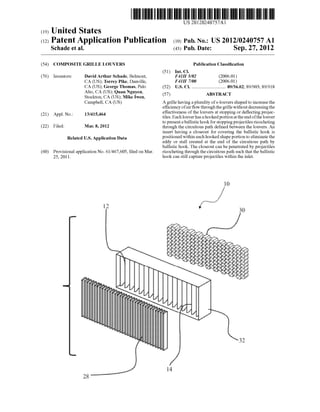
A grille having a plurality of s-louvers shaped to increase the
ef?ciency ofair ?oW throughthe grille Without decreasingthe
effectiveness of the louvers at stopping or de?ecting projec
tiles. Each louver has a hooked portion at the end ofthe louver
to present a ballistic hook for stopping projectiles ricocheting
through the circuitous path de?ned between the louvers. An
insert having a closeout for covering the ballistic hook is
positioned Within each hooked shape portion to eliminate the
eddy or stall created at the end of the circuitous path by
ballistic hook. The closeout can be penetrated by projectiles
ricocheting through the circuitous path such that the ballistic
hook can still capture projectiles Within the inlet.
8. US 2012/0240757 A1
COMPOSITE GRILLE LOUVERS
RELATED APPLICATION
[0001] The present application claims the bene?t of US.
ProvisionalApplicationNo. 61/467,605 entitled “COMPOS
ITE GRILLE LOUVERS, ?led Mar. 25, 201 1, Which is incor
porated herein in its entirety by reference.
FIELD OF THE INVENTION
[0002] The present invention is generally directed to bal
listic louvers permitting the ?oW of air through a vent While
preventingprojectiles fromentering thevent. Speci?cally, the
present invention is directed to ballistic louvers for improving
air ?oW through the vent While maintaining ballistic projec
tion.
BACKGROUND OF THE INVENTION
[0003] Armored vehicles often have intake exhaust vents
for supplying air to engine components and other systems.
HoWever, if a projectile enters the vent, the projectile can
damage the engine or other components. A grille having a
plurality of louvers is commonly ?tted to the intake exhaust
vents to preventprojectiles from entering the engine compart
ment While permitting air to ?oW betWeen the louvers into the
protected area. Grilles typically comprise chevrons as shoWn
in FIG. 1 or S-shaped louvers as shoWn in FIG. 2 that are
arranged in an overlapping con?guration to de?ne a series of
circuitous paths through the vent. As most projectiles travel
along a linear or nearly linear ?ight path, the projectiles
cannot navigate the non-linear paths Without contacting at
least one louver. The louvers typically comprise materials
such as hardened steel or monolithic aluminum that can
de?ect, fragment or capture the projectiles. Although the
projectiles cannot easily navigatethe non-linearpaths de?ned
by the louvers, air can easily ?oW through the non-linear
paths.
[0004] The inherent tradeoffWith a louver protected vent is
that improving protection for the vent typically Worsens the
air ?oW through the vent. Increasing the number of louvers
reduces the likelihood that a projectile can successfully pen
etrate the vent, but also reduces the cross-sectional area
through Which the air can ?oW. While the circuitous ?oW
paths do not block the air ?oW, the supply of air to the engine
compartment can be sloWed if the paths are too narroW. The
sloWed air supply can hinder the performance of the engine
components supplied by the vent. HoWever, reducing the
number of louvers to increase the cross-sectional area of the
circuitous paths increases the likelihood that a projectile Will
penetrate the grille and enter the engine compartment.
[0005] A common feature of S-shaped louvers is a hook
shaped portion, as shoWn in FIGS. 3-5 and as disclosed in
US. Pat. No. 3,901,124, at the end ofeach louver to create an
inlet and a ballistic hook at the end of the circuitous path for
capturing projectiles or fragments that may have ricocheted
through the circuitous path. The reference is hereby incorpo
rated by reference in its entirety. The hooked shaped portion
serves as a ?nal defense against projectiles passing through
the vent. HoWever, the inlet and ballistic hook de?ned by the
hooked shaped portion can create a stall or eddy inthe air ?oW
through the circuitous path upsetting the smooth air ?oW
throughthe grille and creating a large pressure drop across the
vent.
Sep. 27, 2012
[0006] A similar tradeoffis that increasing the siZe or num
ber oflouvers can increase the Weight and pro?le ofthe grille.
As disclosed in US. Pat. No. 5,753,847, a technique for
improving the protective ability of grille is to position an
applique of hardened steel bars in front of the louvers to
fragment the projectiles before the projectiles reaches the
louvers to reduce the impact ofthe projectile. The reference is
hereby incorporated in its entirety. HoWever, the draWback of
the bars is that the bars signi?cantly increase the Weight and
pro?le ofthe grill.
[0007] As such, there is a need for maintaining the protec
tive ability ofthe grille While improving the air?oW through
the circuitous path. Similarly, there is a need for improving
the protective ability ofthe grille While reducing or maintain
the Weight and pro?le ofthe grill.
SUMMARY OF THE INVENTION
[0008] The present invention is directed to a grille having
louvers shaped to increase the e?iciency of air ?oW through
the grille Without decreasing the effectiveness of the louvers
at stopping or de?ecting projectiles. Each louver comprises
an S-shape With a hooked portion at the end of the louver to
present a ballistic hook for stopping projectiles ricocheting
through the circuitous path de?ned betWeen the louvers. An
insert comprising a foam core and covered by a closeout is
positioned Within each hooked shape portion. The insert ?lls
in the inlet in the louver created by the hooked shape portion
to de?ne a continuous S-shape to eliminate the eddy or stall
created at the end ofthe circuitous path by the hooked shape
portion. Alternatively, the inlet can be enclosed by the close
out to de?ne an airpocket Withinthe inlet. The closeout can be
penetrated by projectiles ricocheting through the circuitous
path such that the ballistic hook can capture the projectile
Within the inlet.
[0009] A grille, according to an embodiment ofthe present
invention, comprises a plurality ofS-shaped louvers arranged
in an overlapping con?guration to de?ne a plurality ofcircui
tous paths betWeenthe louvers through the grille. Each louver
comprises a hooked shaped portion at one end de?ning an
inlet and a ballistic hook generally perpendicular to the cir
cuitous path. An insert comprising a foam core can be posi
tioned Within an inlet. The insert can be shaped to “?ll in” the
inlet to prevent the ballistic hook from creating eddies or
stalls as air ?oWs through the circuitous path. The insert can
further comprise a closeout comprising a material positioned
over the foam core to provide a continuous surface creating a
smooth air ?oW. Alternatively, the closeout can be positioned
over the inlet With a foam core so as to de?ne an air pocket
Within the inlet.
[0010] In one aspect, a plurality of hardened bars can be
positioned in front of the louvers to fragment or degrade
incoming projectiles before the projectiles reach the louvers.
Similarly, in one aspect, an open honeycomb mesh can be
positioned behind to capture the remaining projectile frag
ments that ricochet through circuitous path and are not cap
tured by the ballistic hooks of the louvers. In this aspect, the
louvers can comprise a loW Weight composite material to
offset the increased Weight from the bars and mesh.
[0011] In one aspect, a method of preventing projectiles
from entering a vent comprising the steps of positioning a
plurality of S-shaped louvers in the vent, Wherein each louver
comprises a hook shape portion de?ning an inlet and a bal
listic hook oriented to capture projectiles at one end of the
louver. The method further comprises arranging the S-shaped
9. US 2012/0240757 A1
louvers in an overlapping arrangement to de?ne a plurality of
circuitous routes betWeen the louvers for the passage of air
through the vent. Finally, the method comprises positioning
an insert Within the inlet to enclose the ballistic hook to
prevent disruption ofthe air ?oW through the circuitous path,
Wherein the insert comprises a loWer density material than the
louver such that the projectile can penetrate the insert and be
captured Within by the ballistic hook.
[0012] The above summary of the various representative
embodiments ofthe invention is not intended to describe each
illustrated embodiment or every implementation ofthe inven
tion. Rather, the embodiments are chosen and described so
that others skilled in the art can appreciate and understand the
principles and practices of the invention. The ?gures in the
detailed description that folloW more particularly exemplify
these embodiments.
BRIEF DESCRIPTION OF THE CLAIMS
[0013] The invention can be completely understood in con
sideration of the folloWing detailed description of various
embodiments ofthe invention in connection With the accom
panying draWings, in Which:
[0014] FIG. 1 is a cross-sectional side vieW of a prior art
grille having a plurality of chevron shaped louvers.
[0015] FIG. 2 is a cross-sectional side vieW of a prior art
grille having a plurality of S-shaped louvers.
[0016] FIG. 3 is a cross-sectional side vieW of a prior art
grille having a plurality of S-shaped louvers each de?ning a
hooked portion.
[0017] FIG. 4 is a cross-sectional side vieW of a prior art
grille having a plurality of S-shaped louvers each de?ning a
hooked portion.
[0018] FIG. 5 is a cross-sectional side vieW of a prior art
grille having a plurality of S-shaped louvers each de?ning at
least tWo hooked portions.
[0019] FIG. 6 is a rear vieW of a representative vehicle
having a grille according to an embodiment of the present
invention.
[0020] FIG. 7 is an exploded perspective vieW of a grille
according to an embodiment of the present invention.
[0021] FIG. 8 is a cross-sectional side vieW of a grille
according to an embodiment of the present invention.
[0022] FIG. 9 is a partial perspective vieW ofan inner end of
a louver according to an embodiment ofthe present invention.
[0023] FIG. 10 is a representative cross-sectional side vieW
ofan arrangement of louvers according to an embodiment of
the present invention illustrating the How of air through the
louvers.
[0024] While the invention is amenable to various modi?
cations and alternative forms, speci?cs thereof have been
shoWn by Way of example in the draWings and Will be
described in detail. It should be understood, hoWever, that the
intention is not to limit the invention to the particular embodi
ments described. On the contrary, the intention is to cover all
modi?cations, equivalents, and alternatives falling Within the
spirit and scope of the invention as de?ned by the appended
claims.
DETAILED DESCRIPTION
[0025] As shoWn in FIGS. 6-9, a grille 10, according to an
embodiment ofthe present invention, comprises a plurality of
S-shaped louvers 12 each having an exterior end 14 and an
interior end 16. In one aspect, the exterior end 14 can com
Sep. 27, 2012
prise a tapered shape to minimiZe disruption of the air?oW
through the grille 10. The interior end 16 further comprises a
hooked portion 18 de?ning an inlet 20 in the louver 12 and a
ballistic hook 22 generally perpendicular to the louver 12.
Each louver 12 further comprises an insert 22 shaped to ?t
Within the inlet 20 and comprising a foam core 24 and a
closeout 26. In another aspect, the louver 12 can only com
prise the closeout 26 to de?ne an air pocket in the inlet 20. In
one aspect, the louvers can be about 3 inches long.
[0026] In one aspect, the louvers 12 can comprise a com
posite material rather than a metal to reduce the overall
Weight of the grille 10 While improving the ballistic protec
tion of the grille 10. The composite material can capture
projectiles With the same effectiveness as steel or aluminum at
a fraction ofthe Weight. The composite material can comprise
a non-Woven ?brous material impregnatedWith a thermoplas
tic or thermoset resin matrix material. In one aspect, the
?brous material can comprise aramid (KEVLAR) or S2 glass
?bers. In one aspect, the composite material can comprise
60-80 Wt % ?brous material and 20-40 Wt % matrix material.
The composite material can formed by manufacturing pro
cesses including, but not limited to, pultrusion, hand lay-up or
resin infusion methods.
[0027] Similarly, the foam core 24 can comprise a medium
to high density closed cell foam having a loWer density than
the composite material used for the body ofthe louver 12. In
one aspect, the closeout 26 can comprise the same composite
material as the body of the louver 12.
[0028] As shoWn in FIGS. 8-10, the louvers 12 can be
positioned in parallel to de?ne a plurality of circuitous paths
betWeen the louvers 12. The exterior ends 14 ofthe louvers 12
are each oriented toWard the exterior of the vent into Which
the grille 10 While the interior ends 16 of the louvers are
oriented toWard the vehicle compartment to be protected. The
curved portions of the louvers 12 are positioned in an over
lapping arrangement such that no linear path betWeen the
louvers 12 exists. In one aspect, the louvers 12 can be posi
tioned about 0.75 inches apart. In another aspect, the louvers
12 are nested such that the How path through the grille 10
betWeen the louvers 12 is about 50% of the cross-sectional
area of the grille 10. Projectiles travelling along a generally
linear path cannot navigate betWeen the louvers 12 Without
contacting the louvers 12. The louvers 12 are shapedto de?ect
or capture projectiles that contact the louver 12.
[0029] As shoWn in FIG. 10, air can navigate the circuitous
path betWeen the louvers 12 and pass through the grille 10.
The S-shaped louver 12 provides a loWerpressure drop across
the louvers 12 than other shapes. The closeout 26 presents a
continuous airfoil along the length ofthe louver 12 such that
eddies or stalls does not form at the end ofthe louver 12 as a
result ofthe inlet 20 and ballistic hook 22. The closeout 26 is
suf?ciently rigid to maintain the continuous airfoil as the air
travels betWeen the louvers 12. If a projectile is de?ected
doWn the circuitous path, the loWer density of the foam core
24 or the empty space ofthe air pocket alloW the thin closeout
26 to be penetrated by the projectile such that the projectile
enters the inlet 20 and is captured by the ballistic hook 22.
[0030] As shoWn in FIG. 8, in one aspect, the grille 10 can
further comprise a plurality ofhardened bars 28 in front ofthe
exterior ends 14 ofthe louvers 12. The hardened bars 28 can
comprise a hardened metal or other hardened material such
that the bars 28 can fragment or otherWise erode the projec
tiles before the projectiles reach the louvers 12. In one aspect,
the bars can be arranged in a 30 to 40 psf array.
10. US 2012/0240757 A1
[0031] As shown in FIG. 8, in one aspect, a honeycomb
mesh 30 can be positioned behind the interior ends 16 of the
louvers 12. The honeycomb mesh 30 can capture any remain
ing projectiles that survive ricocheting through the circuitous
paths. In particular, the mesh 30 can act as a ?lter capturing
small fragments of projectiles that have broken up passing
through the louvers 12. The mesh 30 can be constructed of
any lightWeight material knoWn in the art such as aluminum,
ceramic, plastic, carbon ?ber, or composite material.
[0032] In one aspect, the grille 10 can further comprise a
frame 32 for simplifying installation of the grille 10. The
louvers 12 and mesh 30 can be pre-bonded to the frame 32,
While the bars 28 can be pre-Welded to the frame 32 such that
the entire frame 32 can be installed into a vehicle 11 as a
single unit as shoWn in FIG. 6.
[0033] The grille 10 can be a?ixed to a plurality ofarmored
vehicles 11 including, but not limited to tanks, infantry ?ght
ing vehicles, armored cars or self-propelled artillery. As
depicted in FIG. 6, the grille 10 is installed over the air supply
vents for the engine of an MlAl Abrams tank. The ?gure is
intended to be representative ofthe installation ofthe grille 10
and not intended to be limiting With regards to the vehicle 11
on Which the grille 10 can be installed.
[0034] In one aspect of the present invention, a method of
preventing a projectile from entering a vent comprises posi
tioning a plurality ofS-shaped louvers 12 in the vent, Wherein
each louver 12 de?nes an inlet 20 and a ballistic hook 22. The
method further comprises arranging the S-shaped louvers 12
in an overlapping arrangement to de?ne a plurality of circui
tous paths betWeen the louvers 12 alloWing airto How through
the vent While denying projectiles a direct linear path through
the vent. Finally, the method comprises positioning an insert
22 Within the inlet 20 to cover the ballistic hook 22 and de?ne
a continuous s-shape along the entire louver 12, Wherein the
insert 22 comprises a loWer density material than the louver
12 such that the projectile can penetrate the insert 22 and be
arrested by the ballistic hook 22.
[0035] While the invention is amenable to various modi?
cations and alternative forms, speci?cs thereof have been
shoWn by Way of example in the draWings and described in
detail. It is understood, hoWever, that the intention is not to
limit the invention to the particular embodiments described.
On the contrary, the intention is to cover all modi?cations,
equivalents, and alternatives falling Within the spirit and
scope of the invention as de?ned by the appended claims.
1. A ballistic grille forpreventing projectiles from entering
a protected vehicle compartment through an air supply vent
While alloWing air to How into the protected compartment
through the vent, comprising:
a plurality of S-shaped louvers each having an exterior end
and an interior end, Wherein each louver further com
prises a hook portion at the interior end de?ning an inlet
in the louver to form a ballistic hook for catching pro
jectiles; and
a plurality of inserts comprising a closeout permeable by
projectiles, Wherein each insert is a?ixed to the hook
portion of a corresponding louver;
Wherein the S-shaped louvers are arranged in an overlap
ping con?guration to de?ne a plurality of circuitous
paths through the vent betWeen the louvers and to deny
projectiles a linear path through the vent, Wherein the
inserts are positioned to enclose the inlet andthe ballistic
hook to maintain a continuous How of air through the
corresponding circuitous path.
Sep. 27, 2012
2. The ballistic grille ofclaim 1, Wherein the exterior end of
each louver comprises 1 tapered shape to facilitate the How of
the air into the circuitous paths.
3. The ballistic grille of claim 1, Wherein each closeout
forms an enclosed air pocket Within the corresponding inlet.
4. The ballistic grille ofclaim 1, Wherein each insert further
comprises a foam core positioned Within the corresponding
inlet, Wherein the foam core comprises a loWer density mate
rial than the louver such that projectiles can penetrate the
foam core.
5. The ballistic grille of claim 4, Wherein the foam core
comprises a closed-cell foam material.
6. The ballistic grille of claim 1, Wherein the louver com
prises a composite material combining a ?brous material and
a matrix material.
7. The ballistic grille of claim 6, Wherein the ?brous mate
rial is selected from a group consisting of aramid, S2 glass
?bers and combinations thereof.
8. The ballistic grille of claim 6, Wherein the ?brous mate
rial comprises about 60-80 Wt % of the composite material
and the matrix material comprises about 20-40 Wt % of the
composite material.
9. The ballistic grille of claim 1, further comprising a
plurality ofhardened bars positioned proximate to the exter
nal ends of the louvers for fracturing and eroding incoming
projectiles before the projectiles reach the louvers.
10. The ballistic grille of claim 1, further comprising a
honeycomb meshpositionedproximate to the internal ends of
the louvers for capturing projectiles that ricochet through the
circuitous paths.
11. A louver for preventing projectiles from entering a
protected vehicle compartment through an air supply vent
While alloWing air to How into the protected compartment
through the vent, comprising:
an exterior end;
an interior end having a hook portion de?ning an inlet in
the louver to form a ballistic hook for catching projec
tiles; and
an insert having a closeout permeable by projectiles
enclosing the inlet and ballistic hook;
Wherein the louver comprises an s-shape such that the
louver can be arranged in an overlapping con?guration
With other S-shaped louvers to de?ne at least one circui
tous path through the vent betWeen the louvers and to
deny projectiles a linear path through the vent;
Wherein the insert prevents the ballistic hook from disrupt
ing the How of air through the circuitous path.
12. The louver of claim 11, Wherein the exterior end com
prises a tapered shape to facilitate the How ofthe air into the
circuitous path.
13. The louver of claim 11, Wherein the closeout forms an
enclosed air pocket Within the corresponding inlet.
14. The louver of claim 11, Wherein the insert further
comprises a foam core positioned Within the corresponding
inlet, Wherein the foam core comprises a loWer density mate
rial than the louver such that projectiles can penetrate the
foam core.
15. The louver of claim 14, Wherein the foam core com
prises a closed-cell foam material.
16. The louver ofclaim 11, Wherein the louver comprises a
composite material combining a ?brous material and a matrix
material.
11. US 2012/0240757 A1
17. The louver of claim 16, wherein the ?brous material is
selected from a group consisting of aramid, S2 glass ?bers
and combinations thereof.
18. The louver of claim 16, Wherein the ?brous material
comprises about 60-80 Wt % of the composite material and
the matrix material comprises about 20-40 Wt % ofthe com
posite material.
19. A method ofpreventing projectiles from entering an air
supply vent for a protected compartment, comprising:
positioning a plurality of S-shaped louvers in the vent,
Wherein each louver comprises a hook shape portion
Sep. 27, 2012
de?ning an inlet in the louver to form a ballistic hook for
capturing projectiles;
arranging the S-shaped louvers in an overlapping arrange
ment to de?ne a plurality ofcircuitous routes throughthe
vent for the passage ofair and denying projectiles linear
paths through the vent; and
enclosing the inlet With a closeout permeable by a projec
tile to prevent the ballistic hook from disrupting the air
?oW through the circuitous route.
* * * * *