
Recommended
Recommended
More Related Content
Similar to 20-Radiophone-Diagrams.pdf
Similar to 20-Radiophone-Diagrams.pdf (20)
Recently uploaded
Recently uploaded (20)
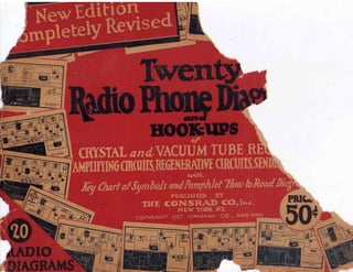
20-Radiophone-Diagrams.pdf
- 1. eni Ile CUUM T GENERATIVE ( with. andPamphk PUBLISHED 11 ONSRAD NEW YORK /927 CONSIZAD ty Dias BE R IRCUITS,SEN k Re CO, lite. CO., NEW YORK I AtAD10 D1A.GRA T[,,,,,,, r WS AL and rt ofSymbo THE COPY/VG grit
- 2. Twenty Radio Phone Diagrams and Hook-ups OF CRYSTAL AND VACUUM TUBE RECEIVERS AMPLIFYING CIRCUITS, REGENERATIVE CIRCUITS AND SENDING CIRCUITS WITH KEY CHART OF RADIO SYMBOLS THE CONSRAD COMPANY, Inc., Publishers 64 CHURCH STREET, NEW YORK, N. Y. HOW TO READ RADIO DIAGRAMS ADupIOs diagramsean be proersewntireidng fnctirwcouiwtsa, yaslsooncealed olfw`h`Hicohokis- in schematic or symbolic drawing, in which each instrument and part is represented by a certain symbol. These symbols have been adopted by radio engineers for convenience sake, as well as for the speed and accuracy with which schematic diagrams can be drawn. However, many people entering the radio field have no knowledge of these symbols, and for them radio diagrams are drawn in perspective drawing, in which each instrument is represented actually as you see it. A Key Chart showing the perspective view of the instru- ment, its name and the schematic symbol representing it, will be found on the back of this instruction leaflet. You will note that there is a certain definite reason for each symbol. A coil of wire is represented by a series of curls as may be seen by referring to the vario-coupler symbol (4) in the schematic diagram. Variable contacts such as provided for by a series of switch points and levers (5) are represented in the schematic diagram by arrows. The plates of condensers, regardless of the number, are represented (7 and 12) by two parallel straight lines. If the condenser is variable, an arrow (2) is drawn through the two lines at an angle. A resistance is always repre- sented by a line resembling the teeth of a saw. If it is fixed, the connections are made to the extreme ends (6). If it is variable, one connection goes to one end and the other to an arrow as will be seen by referring to the rheostat symbol (10) in Fig. 2. The elements of the vacuum tube, namely, the filament, grid and plate, are clearly shown VARIO- COUPLER VARIABLE CONDENSER GRID CONDENSER PHONES FIXED CONDENSER RHEOSTAT "13- BATTERY 13 eta FIG. 1 In our twenty diagrams we have shown all the circuits in picture form, (perspective) as well as in symbolic form, (schematic). It is much simpler to read a schematic circuit as all the paths through the various instruments can be readily traced out. However, when the beginner connects up a set, it is easier for him to consult the perspective diagram, as he can see a picture of the actual instruments which he is using. In order to learn how to read schematic circuits we give an example herewith. In Fig. 1 we show all the connections of a single -circuit regenerative tuner with each instrument pictured thereon. This is a perspective diagram. In Fig. 2, the same circuit is given in schematic form. Copyright 1927, the Consrad Co., Inc., New York in the schematic diagram (8) while in the perspective diagram the binding posts which are connected to the elements are labeled. The derivation of the symbol repre- senting the phones (11) is easily seen. Since each cell of a battery has two elements, they are taken in consideration in the symbol for the battery and since many cells are connected in series, they are represented as shown in the "A" and "B" battery symbols, (9 and 13). By thus referring from Fig. 1 to 2 and to the Key Chart, the reader can very soon accustom himself to reading schematic diagrams. It is advantageous to practice the reading of schematic diagrams as most circuits in news- papers and magazines are represented in this form. Printed in U. S. A.
- 3. (1) Double Slide Tuning Coil With Crystal Detector This circuit is more selective and flexible than one using a single slide coil. The size of the coil depends upon the wave length to be received. This receiver may be used with any type of aerial. To tune the circuit, the slider connected to the ground in the diagram is moved until a station is heard; then the other slider connected to the aerial is moved slowly until the signals are heard at maximum intensity. The secondary circuit is adjusted by moving the other slider to improve the audibility. To reduce interference, the two sliders should be moved together so as to retain the same number of turns forming the primary circuit between them. (2) Loose Coupler With Crystal Detector In this circuit a loose coupler is used, which may be of any size and connected to any form of aerial. The advantage of the loose coupler over the ordinary tuning coil is that two circuits are used which may be coupled together more or less according to the intensity of signals to be received. When interference from another station is experienced, it may be cut out or reduced by loosening the coupling by moving the small coil outside of the primary. (3) Single -Circuit Regenerative Tuner The advantage of the single -circuit tuner are simplicity and ease of adjustment, two important features for the beginner. This circuit with which it is possible to receive telephony, continuous waves, and sparks signals consists of a vario-coupler with the secondary acting as a tickler coil. Such a circuit may be used for the reception of signals on any wave length by increasing the number of turns of the tapped inductance. (4) Honeycomb Coil Receiver For All Wave Lengths This is the standard circuit for a honeycomb coil receiving set with a vacuum tube detector. The coupling between the primary and secondary, and between the secondary and tickler or feed- back coil is variable so that fine tuning is possible as well as sharp adjustment of the regenerative effect obtainable with the tickler coil. By using the proper sizes of coils any wave length can be tuned with this receiver, in which there are no losses in unused part of windings, since the inductances are wound to the proper number or turns to cover a certain range of wave -lengths when shunted by a .001 M.P. variable condenser. By means of the series -parallel switch in the primary circuit, the variable condenser may be short-circuited or used in series or parallel with the primary coil. When it is connected in series. it reduces the wave length of the circuit, while when it is in parallel, that is. connected across the coil, it increases the wave length. The coils used in this circuit are called honeycomb coils on account of the shape of the winding, which instead of being wound in layers, is wound in a special fashion with the turns crossing each other at a certain angle to improve the efficiency. (5) Tuned Plate Regenerative Circuit If the plate circuit of a vacuum tube detector is tuned by means of a variometer. it is possible to bring a vacuum tube to a point where its sensitiveness is very much increased, producing at this point high amplification of tile received energy. By adjusting the plate inductance so that the vacuum tube produces oscillations, it becomes possible to receive continuous wave signals produced by transmitters using vacuum tubes, arcs, or high -frequency alternators. (6) Standard Short Wave Regenerative Set In the standard short wave regenerative circuit, shown in this drawing. the tuning of the grid and plate circuits is done by means of variometers producing a continuous variation of the inductance in both the circuits. For short wave reception this is hest, as under these conditions the vacuum tube detector which is operated by potential. functions at maximum efficiency since there are little losses in any condensers-inductance alone being used. The vario-coupler is exactly the same apparatus as the loose coupler shown in diagrams Nos. 2 and 5, the only difference being that instead of pulling the small coil outside of the primary, it revolves one -quarter of a turn inside of it. When the turns are in the same plane, the inductance between the coils is maximum; while when the secondary or rotor coil is turned at right angles, there is no induction. This provides a means of obtaining a zero value of coupling. (7) The Reinartz Circuit The circuit illustrated does not possess any wonderful advantages for the reception of radio phone signals but when used for receiving C. W. (Continuous Waves). it stands out above all other types. The ease with which a C. W. station is tuned in and held without changing in strength is remarkable and the distance over which such signals can be received is a revelation to the uninitiated. As will be seen from the diagram there are only two coils. Both of them are wound on the same tube; a space of about one -quarter of an inch being left between the two windings. These two coils might also be wound on a single spider web form, the inside diameter being about two inches. Approximately the same number of turns can be used as indicated. It is quite necessary that the moveable plates of the two condensers be connected to the aerial and ground respectively. This aids in the tuning of the set as well as in holding signals. It will be further advantageous to use a vernier attachment on the condenser connected in series with the plate coil. If the builder desires lie may shunt the phones and "B" battery with a mica fixed condenser having a capacity of a .001 mf. (8) Cockaday Four Circuit Tuner The unique feature of this circuit is the single turn inductance connected in series with the antenna and tho stabilizer circuits. The single turn affects the stabilizer circuit which, in turn, affects the secondary. The wave length of the primary circuit is brought up by means of the tapped inductance coil connected in series with the single turn. The stabilizer and secondary circuits are both wound on the same tube within one thirty-second of an inch of each other and the data on them is given in the drawing. The single turn consists of No. 14 bare copper wire and is wound directly over the stabilizer coil and about one-fourth of an inch from the beginning of it. The primary loading inductance is wound on a separate tube three and one-half inches in diameter and tapped as indicated. Greater efficiency is obtained if this coil is bank wound. When the instruments are mounted, this coil should be placed in a non -inductive relation to the other coils. The data given in the diagram is suitable for a wave length range of 150 to 550 meters. This circuit is extremely selective and gives excellent results on spark. continuous wave and radio phone reception. (9) Short -Wave Regenerative Set With Two -Step Amplifier When a two-step amplifier is used in conjunction with a short- wave regenerative receiver, the range is considerably increased because the signals are so amplified that they may be heard in the telephones while they would he barely readable with the detector tube alone. When it is desired to operate a loudspeaker, 60 or more volts should be used in a plate circuit of the vacuum tubes. There are no special connections for the loudspeaker which is merely inserted in place of the telephones. (10) Detector and Two-Stage Amplifier With Automatic Filament Control Jacks The advantage of automatic filament control in an amplifier is that it is not necessary to turn off the filament current of each tube when only the detector or one step of amplification is used. Plugging in the telephones in any of the jacks, opens and closes the proper circuits automatically. This is a great advantage, for the rheostats may be left adjusted in proper position all the time. (11) Push -Pull Amplifier Many radio amateurs desire to get as much volume as possible out of their receiving sets but find that when they carry the amplification to a certain point. great distortion takes place which often renders it practically impossible to understand the music or voice emanating from the loudspeaker. In order to overcome this difficulty, and still preserve the desired volume and in some cases even increase it, engineers have developed what is known as the push-pull audio frequency amplifier. This device uses two ainplif.Ong tubes connected in parallel. To use this amplifier which consists of two tubes, the receiving set itself must contain at least a detector and one stage of audio frequency amplification. The output of the latter is connected directly to the input binding posts of the two tube push-pull amplifier. The current then goes into a transformer where it is stepped up and fed to both of the two tubes. These tubes are so balanced that their energy is combined in the output transformer which connects to the loudspeaker and a maximum volume of sound with a mini, mum of distortion is obtained. The transformers wound on an iron cores having single primarys with two secondaries of an equal size on each transformer. The ratio between the two windings is approximately four to one. On the whole. the push-pull amplifier circuit will usually not give very much louder signals when used as shown in connection with a detector and one stage amplifier than a standard tuner employing a detector and two stages of audio frequency amplification. However. the reproduced sounds will be of such better quality and so free from distortion that the use of the extra tube will be fully justified. (12) Reflex Circuits By using a special hook-up employing a combination of both radio and audio frequency transformers, it is possible to make a single vacuum tube amplify both high and low frequencies In the same circuit. Usually a crystal detector is used for rectification in these circuits. but if desired a vacuum tube can be substituted for the same. However, the crystal detector will give clearer signals and will reduce the internal noises characteristic of some vacuum tube sets to practically a minimum. Careful adjustment of the poten- tiometer will also assist in this case. It is inadvisable to try to use either one of these illustrated circuits without this piece of apparatus. It should have a resistance of from 200 to 400 ohms. In the one and two tube circuits we have indicated a vario- coupler and variable condenser for tuning. Any type of tube may be used in these circuits providing it is an amplifier with as small an internal capacity as possible and will stand a plate voltage of at least 45 volts. Higher voltages will give louder signals up to the paralyzing point of the tube A word as to the transformers. Standard audio frequency and radio frequency tiar.sformers will give good results and those designed for first and second stage work should be used in their respective places. It is quite necessary that the transformers be matched up correctly in order that good results be obtained. (13) The Harkness Reflex The popularity of the reflex circuits described in the above paragraphs has become very great since their introduction to the radio public. Many supposedly new reflex circuits have appeared since then, some of them good and some of them bad. We present herewith a description of one of the best of these
- 4. outgrowths Known as the Harkness Reflex. This circuit, as may be seen by glancing at the diagram, employs two vacuum tubes and a crystal detector. Such a set when properly connected with the correct transformers and other apparatus gives the results of three vacuum tubes and a crystal detector. The first tube is used twice, once to amplify at radio frequency and once at audio frequency. The crystal detector is used for rectification and as the signal passes into the first tube and is amplified at radio frequency, the crystal puts in its good work and sends the signal back to the grid circuit of the first tube. Here it is again amplified at audio frequency and fed directly into the second tube. The second tube is a straight audio frequency amplifier and it renders the signal very loud. This two tube set when constructed properly will furnish ample power to operate a loudspeaker. The unique feature of this set is the construction of the radio frequency transformers. These are labeled F and Fl in the diagram. The first one serves to tune the antenna and secondary circuit and is constructed as follows. On a 2Wh inch tube, wind 60 turns of No. 24 D. S. C. wire. Directly over the center of this winding and separated from it by a layer of waxed paper, wind twenty turns of the same sized wire. This is for the antenna tuning transformer. The transformer between the first tube and the crystal detector, Fl, is constructed in much the same manner and the secondary winding is the same. The primary, however, consists of 32 turns of No. 24 D. S C. wire. Because of the peculiar method of connecting the instruments in this circuit, a stabilizing potenti- ometer is not necessary and without it the set does not generate continuous oscillations and, therefore, cannot radiate and annoy operators using nearby receiving sets. Furthermore, the absence of oscillation makes possible much clearer reception. (14) Loop Aerial Receiver Excellent results may be obtained with a loop or coil aerial when used with this two -tube circuit. The first tube acts as an amplifier, boosting the very weak current received in the loop so as to operate the second tube, which is the detector, at maximum efficiency. For the reception of short wave lengths. the loop, which is on wooden frame 4% feet square, should be wound with four turns of No. 29 insulated wire with the turns spaced one-half an inch apart. The regenerative coupler consists of two coils L and Li, the latter turning inside of the former. Coil L consists of about 14 turns of No. 16 insulated wire, wound on a cardboard tube three inches in diameter. Coil LI, which can rotate half a turn, is wound with GO turns of No. 26 single cotton wire. (15) The Superdyne A unique example of the use of the feed -back principle is found in the Superdyne receiver which has lately made its appearance and which has given excellent results. Instead of using feed -back to produce regeneration and consequently louder signals a tickler coil is used to control the oscillations in a radio frequency amplifier and prevent the usual noises encountered when using this type of receiver. The connections of this set are rather peculiar, that is, in the radio frequency plate circuit. As will be noticed, the leads to the rotor are reversed from the position which would ordinarily cause regeaemtion and instead of being conneet,d directly to the plate, one of the leads goes to the high voltage of the "B" battery and the other to one side of a tuned impedance coil. This coil is tuned by means of a .0005 mf. variable condenser. Wonderful results have been obtained with this type of receiver as a point bordering very closely on oscillation :an he reached in the radio frequency amplifying circuit without causing- the tube to oscillate. Doing this, of course, makes the tube considerably more sensitive and allows much greater amplification. in order to use this receiver, it is necessary to construct the coils very carefully following the specific data given herewith and on the diagram. The best way you can go about constructing the coupler would be to purchase a standard vario-coupler and rewind it to suit the specifications given. After winding and tapping the secondary as indicated, wind directly over the center of four turns of No. 22 D. C. C. wire. Space these turns one-fourth of an inch apart and separate them from the secondary by means of a layer of waxed Paper. The data on the tuned impedance coil is given and it should also be tapped as shown. The purpose of the taps on the impedance coil and the secondary is to allow a variation of wave- length. The approximate wavelength range using the smaller and larger sections of the two coils is from 176 to 358 meters and from 310 to 660 meters. Thus, it will be seen that this receiver can be used both on amateur wavelengths and for ordinary broad- cast reception. Experiments with the Superdyne have shown that unless at least one stage of audio frequency amplification is used, the results are not very good. Therefore, it is advisable to use one and preferably two stages of audio frequency amplification. Thus, a loudspeaker can readily be operated. (16) The Teledyne Since war has been declared on oscillating and radiating receivers, attention has been turned to the addition of radio frequency amplification before the tuner; that is. between the tuner and the aerial and ground. Such an addition acts as a sort of a "muffler" and prevents oscillations which are generated in the detector circuit from reaching the aerial and thus causing inter- ference by causing the set to act as a miniature transmitter. From the experimental work done along this line, the Teledyne has sprung. It is nothing more or less than a single stage of radio frequency amplification added in front of a standard untuned primary regenerative circuit. Because of the fact that the plate circuit cannot readily be brought to resonance with the grid circuit of the radio frequency amplifier, no potentiometer has been found necessary and very good results will be obtained without the use of this instrument. The construction of the coils as out- lined herewith and on the diagram should be followed rather lonely as these have been worked out to give the very best results. however, anyone who has constructed a receiver of the untuned primary type can readily add one stage of radio frequency amplification in the manner suggested. The secondary is first wound on a four inch tube and directly over the first turn of it is wound the first turn of the four which constitute the primary winding. These coils are wound in the same direction and sepa- rated by a layer of thin cardboard approximately 1/32nd of an inch thick. The result of this circuit is that one stage of radio frequency amplification builds up the incoming signals whereupon. they are detected and again built up by regeneration in the detector circuit. The standard two -stage audio frequency amplifier then brings the signals up to a point where they will very satisfactorily operate a loudspeaker. The use of a "C" battery is recommended as shown. (17) The Hazeltine Neutrodyne Receiver Tuned radio frequency amplification has not heretofore been used to a very great extent because of the difficulty encountered in keeping the amplifying tubes from oscillating due to the internal capacity of the tubes. However, Professor L. A. Hazeltine has perfected a method whereby this system of reception may be used with great satisfaction and without the usual distortion due to the oscillation of the amplifiers. This method merely makes use of two very small condensers connected as indicated at Cl and C2 in the diagram. These condensers as shown are nothing more than two pieces of bare copper wire enclosed in an insulating sleeve with their ends about three-quarters of an inch apart. Over the insulating sleeve is placed a copper tube, two and three-quarters of an inch long. The transformer used in connection with this circuit consists of two fixed windings wound on a three inch tube. The primary is wound on top of this secondary and directly in the center of the same. Single layer winding is used for both. When the instruments are connected up as shown in the diagram and a station tuned in, the filament of the first tube is extinguished. If signals still come through, the condenser Cl is adjusted by moving the copper tube, until they are inaudible. The first tube is then lit and the same done with the second. When these ad;ust- ments are made the condenser Cl and C2 are sealed. It is no longer necessary to adjust them until new tubes are used, and if the initial adjustment is made correctly it will be found that this circuit will operate consistently without any danger of oscillation in the radio frequency tubes throughout the entire band of wave- lengths. The condensers used for tuning the secondary of the radio fre- quency transformers may have a capacity of from .0003 to .0005 mf. The antenna and secondary inductances may be honeycomb coils or if desired a variometer may be used with a center tap taken from the connection between the rotor and stator windings. (18) Radio and Audio Frequency Amplifier This amplifier circuit is extremely sensitive, and especially adapted for long distance reception with an outdoor aerial, or for use with an indoor loop. By applying a high plate voltage on the audio frequency amplifier tubes a loudspeaker may be operated with success. The loop aerial which may be used with such an amplifier should be of the same design as the one described in diagram 14. (19) The Super -Heterodyne Great interest has been manifested in the Armstrong Super - Heterodyne. This is by no means a new circuit, having been developed during the war for use in France; but never until of late has it become very popular due to its former complexity and to the fact that it required an expert operator. However, the set has been simplified to such an extent that with six tubes great "DX" reception may be expected using headphones. If desired, a standard audio frequency amplifier may be added so as to use a loud- speaker. It will be noted that one of the tubes is used as an oscillator and coupled to the grid circuit of the first tube which acts as a detector. The frequency of the incoming signal is changed so that it is equivalent to that of a higher wavelength; about 3,000 meters with a set built following the data given herewith. The radio frequency transformers indicated should then be designed to operate efficiently on this wavelength. A signal is thus amplified at radio frequency and again detected. Just before it is detected, a tuned transformer is employed. It will be found that after the two condensers across the coils of this tuned transformer have once been set, they may practically be left in that position and most of the tuning done with the secondary and the oscillator condenser. The grid and plate coils of the oscillating circuit are wound on the same tube and No. 22 D. C. C. wire may be fixed. Six turns are wound on a rotor using the same sized wire and it is mounted within the VA inch tube. The rest of the constructional details and all the connections are shown on the diagram. This set. once it is put into operation and once the last R. F. trans- former is tuned carefully, will give excellent results both as to ease of control and distance reception. The circuit is very sharp in tuning and will give excellent all-around results. (20) Five Watt Radio Phone Transmitter For low power radio phone transmission, this circuit will give very good results, being flexible and easy to adjust. The coil connected in the grid circuit can rotate inside of the inductance and permits a fine adjustment, securing maximum radiation for the power used. The modulation transform:r amplifies the weak variations of current produced in the microphone transmitter so that the vacuum tube transmits the weakest sounds. The high voltage applied on the plate of the tube may be furnished by batteries, high -voltage dynamo, or rectified alternating current. The iron -core choke coil connected in one lead from the high-tension source prevents the high -frequency oscillations from flowing through the battery or dynamo. thus short-circuiting the variable condenser connected in the ground lead. The range of such an outfit when 500 volts are used on the plate, is about 25 to 30 miles.
- 5. iii Allir," KEY-CHART TO RADIO SYMBOLS gm i RESISTANCE ( VF AI LRAI AmBELNET) RHEOSTAT AERIAL A1 Al 150 (HoZ`i-ComB) c.,-,, GAP (QUENCHED) -L j=1, RESISTANCE /k AERIAL (Loop) lr SWITCH GROUND =1-- if_ ALTERNATOR OR 0 ,,-;! ':'wV (SPFDTIFTWE B) 0 _--i4: 1Ciktg ' COIL , (TUNING) (1 08-1W 1 , GRID LEAK wwv z j110 - 4- TRANS- FORMER 1./D10 FREQUENCY, () AMMETER 6 OR 0 FORAM RADIO FREQUENCY) 1 i JACK ARC l ^n 1 CONDENSER (FIXED) .. '1"7 cl c_z,,p @e) 100 TRANS - M ITTER . , KEY __,_ 4_.."1--D1 BAT-pl:ERY i1111_ 14".1,11G1 1 il'f....Aj CONDENSER (VARIABLE) cf- # a U VACUUM TUBE_ 6...sc F F 17 ( /CO LOOSE. COUPLER COILS WITH VARIABLE COUPLING - - - - .- Z. CONNECTION e:1 BATTERY i Ia NTT) a VARIOMETER ''' NO CONNECTION irmi Nana- DETECTOR (CRYSTAL) cil? BUZZER + , °' DYNAMO OR MOTOR POTENTIO- METER 4 t. VARIO- COUPLER fir %iii4i COLE 1 (SRPIK ) to, or t RECEIVER (TELEPHONE) Ccb COIL VOLTMETER 0 I Copyright 1924 Consrad Co. I ac. Nework,N.Y.
- 6. TO AERIAL SI DOUBLE SLIDE /TUNING CO/L TO GROUND CRYSTAL. DETECTOR TELEPHONES TELEPHONE CONDENSER * , .00/ MP -IP-- V fiER/.4 L_ J. O CR Y5 TA L DETECTOR .11111w .11M WEI 4111110 TELEPHONE R41)Ho/vE)_5 .1111110 CONDE/V5ER 411110 . 00 / MF. C04 41M .111110 DOUBLE &WO Alava COIL WITH CRYSTAA alETECTOR (t) LTNE ttle,A5/7"9 M. /NC PRin,rco ?iv
- 7. TO AERIAL LOOSE COUPLER .00/ VAR/ABLE CONDENSER TO GROUND PR/MARY SECONDARY m1aao...a.B.A.01 M /AI, CRYSTAL --- DETECTOR .0005 VAR/ABLE CONDENSER CRYSTAL DE TEC TO/4? PHONES PHONE CONDENSER .001 lir ej LOOSE mama, wierbi CRYSTAL aitia4MR PRIAlreo see 044.o.
- 8. TO AERIAL VAR/ABLE CONDENSER TO "7GROUND', AER/.4 VARIO COUPLER GRID L.E.elh" AND CONDENSER .00025 ',IF: "A" BATTERY RHEOSTAT VAI'? /0 COUPLER 0 0 ,2 -7 GROUND THE CONSRAO CV. ave. 47H/_ e)ST4 7: WVVAAA,1 I- "ABATTER PHONES .0005 /'?.F CONDENSER SINGLE -CIRCUIT 11011111WERAr/VE TUNtif PRINTED USA.
- 9. TO AERIAL 0 SERIES PARALLEL SWITCH 70 GROUND o SEP/ES PARALLEL SW/ T. TAM CON3RAP CD. ANC .0005 /1 f: CONDENSER "8" BATTER)/ VARIABLE CONDENSER GRID LEAK 27-03 MEG. CONDENSER 00025 /yr "A" BATTERY HONEYCOMB WIL RECE/VER FOR ALL W.414111 DNGTHS Pm/tyre° 9,4,
- 10. rio AERIAL V TO GROUND LOOSE COUPLER SEC0i/DARY GPO CiA1,9 VARIABLE CONDENSER .0005 nr GRID LEAK ro 3 MEG. 6R//l LEAK. Ra2 CONDE/v5ER .0005 1-1/-- "r" GRID CONDENSER .00025 CIF R 10 PIE TE 5'L.00ff/NG r/ CONDENSER .00 I PHONES BLOCIONG CONDENSER .00/ Mr -4-- PHONES TUNED PLATE REGENERATIVE C/RCU/T vme conamore co. ,Ac PfieWTED AN Fj. A
- 11. TO AERIAL VAR /0 COUPLER VAR/ABLE CONDENSER TV GROUND TIVS COPV50:40 CO. by a, OR/ D LEA' 2 TO 2 tlEG. GRID CONDENSER . 0002 5 1/ VAR IOP TETER " BATTERY tl) CONDENSER ,000257`9 F:' '13" BATTERY STANDARD SHORT WAVE REGENERATIVE SET #' //v TED try u 5 A
- 12. A 70 AERIAL TAP AT 2,44;.5: 6,7 8,/0, /2 T. 23 PLATE VAR COND. 3"D/A. TUBE N2 20 S. CC WIRE M 20 -ICC WIRE TO GROUND 4 GR/D LEAK' TO 2 ITEGON,15 GR/D CONDENSER .00025 1 -IF 23 PLATE VAR. COND. BAT. 221- 14 ;.! roz riE,:-ofrer15 An 1 .'..)002 5 X' 3 0-- 41.110.. BOTH ,(07, c- WOUND .22/ ":" 5 32.-TyvEL- 4111111b 4 :coos A.10 E 47,[. ATE 5 TO GROUND O. THE Con,50,9,40 a). /NC. -#4- BATTERY ME RE/NARTZ C/RCUIT PRINTED IN 0.1' A.
- 13. 23 PLATE COND. 65r Ng /6 -1"abg. ruse 437: NS Iet cc WIRE TO GROUND G5 Tows °rive .5.econi SAME TUBE AS -5TABIL/ZE 4 34 T or N.2 '18 _5 cc ONE TC11-7),I ^, 3'1" .rueiE /4 BARG 14,11-7E" WOUND b'E- 6/1,11,11NC, CT 5- , 6,/ 4/ 43 TURNS OF /V5 /8 ry TUBE TAPA7f, 0 T / 3 SP 7 711 nte 2/ ANC+ 4,7 5T RIR", 5 7-144- CON.50f14.0 c, IeVC 23 PLATE VAR/ABLE CONDENSER .00025 a TO 2 MEGHOMS 65. CV -1/-1 F?Ht °STA 7 fiA T TER V 111111 4, V. -4- "463- BATTERY 22E V COCKADAY POUR C/Rafir 77.1/V ER /Ivrea IN IAN
- 14. TO AERIAL VAR101'1ETER a VAR/0 COUPLER V4R.1,4CILE, COA/OVER I-33;41 TO ORO UNA., I/AR/01'1E7ER Of.?/12. CO. GRID LEAK neg. .00023 MF CONDENSER VAR/OMETER COAIOENSER .0005MF RI -1E0. B BATTER/ES At-IPZ h. --?-//yo rRA/v3ro".<7,-74-----5 I ../.0C/"." .0005 M. AA/VVA,',, I 1 VAAIV AAA JACM AMPLIFYING TRANSFORMERS 3 k..P111 SHORT-WAVE REGENERATIOE WITH 2 STEP AMPLIFIER'
- 15. TV- TICKLER CO/L OR *PLATE VAR/OMETER GRID LEAK CONDENSER TO SECONDARY OF TUNER TO TICKLER COIL OR' PLATE VAR JOMETER .00025 TO SECONO.QRY OF TUNER riff CON5RAO CO ,WC. 11 I JACK AMPLIFYING TRANSFORMER JAC /-f- , DETECTOR B BAT- 22-h v JACK ADDiriavA, ACTPLIFI EA' 11010 5" rreR/E.5 4.5- 90 V. - /vd-fr-t-v AMPLIFY/NG TRANSFORMER ETECTOR 49- BATTERY 1 ADDITIONAL AMPLIFIER -8 - BATTER/E5 + 0 JACK DETECTOR e a -STAGE AMPL/F/ER WITH AUTOP/AT/C F/ LAMENT CONTROL JACK'S. PR/Nrct) err a SA
- 16. PUSH-PULL TRANSFORMER C' DATTERY RHEOSTAT ...K.1. e 411011111s. ANO ONE Pt, .5 AY f'I LL T N R T,TE" N EC, 5 T.1 T M/1V 7FRNSFr!?7'GF CENTER 7qN C JTPUT TO LOUD SPEAKER PUSH- PULL TRANSFORMER BATTERY 90 TO /20 V. PUSH PULL AMPL./F707 V THE 05INSRAC) CO. INC. PR Nreet IN a SA
- 17. 43 PLATE VAR, COND. OOJSMF .VAR/O COUPLER A.F.T. .001.5" Pie HUH ..4,77,11 02,40140 -004571 A' BAT: --1114111 - I + £: 4.:.;V. 1/24 cr.?, 0 - CO cfc,1_ rvvo 7!)/3E /
- 18. vsto cia.civwci X.7717 rY .7M1 -451 V1-1 .7H_L A212.1.1b`g :21 2000 ' 27NONe -SWleael A314/3/0 -.add oionte 1:12 0111111-.VGL7 A 06 - b. ,Id311bg + II I III I /3 etMQJ S' ce :77Ste.) /.42Y3 /' ' - C) ,. S ) /3 ^// '5' ,Y.7A0 3 ) .. zr = a S.:4211.1 7 O V. :5''G N . 09 .. 5"1 d (Dca tA? ;tidal oa d) 4h. 2/01.72170 7111SAY.7 4- 000 - eFi e/.75W20 Ae0.2 3 7E7 tighlteA !-1 2000 .V2SW3ON0.2 3796'/A/11A
- 19. VARIABLE CONDENSER .0005 TO GROUND F I VAR/ABL E CONDENSER 000 S' CRYSTAL DETECTOR 11, (.0 , 20 TURN 24 05C) t5 = ON TUBES. P_32 i F 0 VE R., 5/N F/ 4, GO ,/ EACH r.4.541: Fi AF' iii III S 5.0T 7E/9 y 45-50V 000 5 PH NE ,5 Fr 'NEI:AS TA T THE COH.9,740 CYd avc e .0005 F AUDIO FRE- QUENCY TRANS. PNONES -A BATTERY THE HARKNE,515 REFLEX PRINTED
- 20. LOOP AERIAL. CUIVUt.IV.SEN THE CCVISPeina CCUNC- REGENERATIVE COUPLER ""1111111.1011P"" CONDENSER .00025 1-1F: GRID LEAK TO 3 /1E -G. PHONES RHEOSTAT -8 "BATTERY 45 - 90 V LOOP AERIAL RECEIVER ~IP/ TED
- 21. k
- 22. 6TURNS OF AA 26 11.5.C.ON.34"TOBE 4TURNS OF Ake 26 D.S.C. A b. 626 P.S.C. ON 22"TUBE It- me coNsAwo co. INC. 45 TURNS OF N-° Z 11.5.0 ON4"TUBE RHEOSTAT .0005 .t9 MEGONMS .00025 4. F. TRANSFORMERS THE TELEDYNE 11 JACK' ,P-v.IV I ,EI.1 11V 4/..7,
- 23. 1111_11., 7707ER7.2"1"1" tti in till NM/LAT/NG SLEEVE COPPER TUBE r/4 DARE COPPER WIRE 'DETAILS orCI AND C-2 6' r *2 -5.0 C rlyv j" 7 UBE ,,,,,,,, GRID LEAK TO.3/1E4 221V. BAT 45-100 V GRID COND.. .00025 nr "A" BATTER Y RHEO. Atoas6 THE /-HAZEL TINE NELITRODME RECE/VER . THE croaRAo co. icor. PRINTED lc A.
- 24. Rpr POTENT/OPIETER r(iAre,L, LOOP ,Ci,-1 /Wit:037A 7 SIVVV RADIO EPEQUENCY IF If I? MC CU, SMA4110 CO //VC R.PT GR/D COND. ,00023711, APT JACK RHE0.5 TA 7 4'0,57A7 PH E 0.5 7/1r 'NNW DE'EE-C7-017 AUDIO FRE-c.f./rile 41121.12/5A? A.fr JACK deb "A" BATTERY JACK zz* "B" BATTERY 4 5 179 90 V. RAD/0 AND ..4440/0 FREQUENCY AMPL/F/ER ifv LI A
- 25. 1,1 TO GROUND %/A PI() COur,LER 0,70.5 6 rctRis/5 N RoroP .0o, / 22 7: On.,' TUBE. 20 T. On, .5.4/.1E 77/BE T/11OONJR.,7G Co. INC. .0005 .0002.5 P. F. 7. -'I- YD .00025 OR/ 45 V R. f:T RRT 13 BATTER)/ THE SUPER HETERODYNE M/WY-EL
- 26. TO AER/AL VAR/0 COUPLER VAR/ABLE CONDENSER TO GROUND, twcRo,ortoivE /10DULAT/ON TRANS. .0005 f: :A BATTERY HEOSTAT ,4ER IA L. VAR /O COUPLER OR OW INDUCTANCE 68/0 COIL .002 MI: IP MICROPHONE MOD UL AT/ON TRANSFORMER JM-Q_OLI II0005 /-1P RHEOSTAT - + VWVV ;4 BATTERY IRON CORE CNOfr E CO/L. 0+ H/GN TENS/ON 0 - THE CONSRAP /NC. - 0 + /RON CORE CHOkE COIL 5 WATT R14D/OPHONE TRANS/V/77a? PRi,v-rra iN 41-J A
- 27. Measurement of Wavelength of Distant Transmitting Station Calibration of a Receiving Set 0-0 0-0 RECEIVING SET -0 A -0G 0- 0 - FIG I. TELEPHONES PRIMAIZY LOAD SECONDARY RECEIVING SET o A DISCONNECT FIG a W-Wavemeter or driver. L-Coupling .:oil of one or two turns. MEASUREMENT OF WAVELENGTH OF DISTANT TRANSMITTING STATION The apparatus required and the circuits employed are shown by figure 1 above. To obtain wave- length, first, using as loose coupling as possible, tune in signal on receiving set, next start buzzer con- nected to wavemeter (W) and adjust wavemeter until the maximum strength of signals is obtained in telephones connected to receiver. The wavelength of the wavemeter (W) is now the same as that used by the distant station. CALIBRATION OF RECEIVING SET First set up wavemeter so it wil. excite secondary (Fig. 2) of receiver. One or two small turns may be connected in series with secondary if wavemeter cannot be conveniently placed to excite it otherwise. Loosen coupling between primary and secondary of receiver as much as possible and set primary switches to shortest wavelength. Next adjust wavemeter to the lowest wavelength the receiver is designed for, and after starting buzzer, tune the secondary of the receiver until the maximum strength of signals is obtained in the telephones, which will be obtained when the receiver secondary is adjusted for the same wavelength as the wavemeter is tuned for. Note adjustment of receiver secondary when this has been accomplished and then increase wavelength setting of wavemeter by about 20 meters. Tune this wavelength in on the secondary and note adjustment. Continue in this way until you have the adjustment for every twenty meters over the entire range of the receiver. When you have accomplished this, plot your results on a piece of cross section paper. When the secondary has been calibrated, the primary can be calibrated by using the circuit shown in Figure 1. From the table previously tabulated adjust secondary for lowest wavelength, and adjust wavemeter for the same wavelength. Now using a loose coupling tune primary until maximum strength of signals is obtained in telephones attached to receiver. Wavemeter, primary of receiver and secon- dary of the receiver are now all adjusted to the same wavelength. Continue in this way, noting setting of primary each time, until you have covered wavelength range of receiver again. A cali- bration curve for the primary can then be drawn similar to the one for the secondary. No. 5. Copyright 1:22 by the Consolidated Radio Call Book Co., Inc. 98 Park Place, New York City
- 28. Measurement of Fundamental Wavelength of Antenna Three Methods TELEPHONE FIG a (a) Buzzer excitation. (b) Buzzer excitation. (c) Spark excitation. 77FIG. 3 WI-Wavemeter used as driver. (Fig. 1.) Ws-Wavemeter used as detector circuit (Fig. 2). Wr-Wavemeter used as detector circuit with detector connected unilaterally (Fig. 3). Li LI-Small loops used for coupling. IA-Small inductance of 1 or 2 turns. (a) BUZZER EXCITATION The apparatus required and the circuits employed are shown by Figure 1. Care must be taken that coils of wavemeter and detector circuits are placed so that no energy is transferred from one to the other except via loops L, and L2 and the antenna circuit. To measure the wavelength of antenna, start the buzzer and then tune wavemeter until maxi- mum signals are obtained in the detector circuit. (b) BUZZER EXCITATION The apparatus required and the circuits employed are shown by Figure 2. A battery and buzzer are connected across a small series inductance of one or two turns L, and the wavemeter is used as a detector circuit to measurc the wavelength. The error due to the inductance IA is small and can be neglected. (c) SPARK EXCITATION Connect antenna and ground to two sides of a plain open gap (Fig. 3) which is supplied with current from secondary of power transformer. Condenser and oscillation transformer must be dis- connected from the circuit. Use wavemeter as a detector circuit to measure wave length. No. 4. Copyright 1922 by the Consolidated Radio Call Book Co., Inc. 98 Park Place, New York City
- 29. C. FIG Measurement of Capacity DETECTOR CIRCUIT Substitution Method TEL a .001 .0009 .0008 ,0007 .0006 .0065 .0004 .0003 .0005 .0001 IIEG EE 5 .0 20 36 40 50 -0 70 b0 0 I 0 I 0 1$0 130 IA Li-Variable inductance. L,-Coupling coil. C.-Standard calibrated variable condenser. C.-Capacity to be measured. G -Galvanometer and thermo element. W-Wavemeter or driver. The apparatus required and the circuits employed are shown by Figures 1 and 2 above. The principle of determining the capacity is the same in both figures, but different methods are employed to determine when the circuits are in resonance. In Figure 1 a detector and telephone receivers are employed; in Figure 2 a thermo element with a galvanometer. To determine capacity of C. start buzzer connected to wavemeter and with switch thrown so as to cut C. in circuit, vary wavelength emitted by wavemeter until maximum strength of signals (Fig. 1) is obtained in telephone receivers, or a maximum deflection (Fig. 2) is obtained on gal- vanometer. When this has been accomplished, without disturbing the rest of the circuit, throw switch so as to disconnect C. and connect C. in circuit. Now vary capacity of C. until maximum strength of signals or maximum deflection is obtained again. The capacity of C. now equals the capacity of C. and as the capacity of C. is known, you have the capacity of C. for this setting. If C. is a variable condenser you desire to calibrate, the capacity for every ten degrees of scale should be obtained by the method just outlined, and the resulst plotted on cross-section paper. An example of a calibration curve is shown above. Note.-In the circuit shown in Figure 1 care must be taken to place the coils far enough apart and in such positions that there will be no direct transfer of energy from the driver to the detector circuit. No. 1. Copyright 1922 by the Consolidated Radio Call Book Co., Inc. 98 Park Place, New York City
- 30. Measurement of Inductance of a Coil or Circuit FIG. I (Two Methods) OETECTOR CIRCUIT W-Wavemeter or driver. L.-Calibrated variable inductance. L.-Inductance to be measured. Lf-Coupling coils. S.-Stopping Condenser. (a) SUBSTITUTION METHOD FIG. The apparatus required and the circuits employed are shown by Fig. 1. To obtain inductance of L. start buzzer and with switch thrown so as to connect L. in circuit tune wavemeter until maximum strength of signals is obtained in telephones connected to detector circuit. Next without disturbing the rest of the circuit throw switch so as to disconnect L. and to connect Ls in circuit. Now vary the inductance of L. until maximum strength of signals is again obtained in telephones. Inductance of L. now equals L. and as the inductance of L. is known you have the inductance of L.. L. is generally a variometer, or a variable inductance consisting of two rollers, one of metal and the other of an insulating material, with means for winding wire from one to the other to obtain a continuous variation of inductance. (b) BY CALCULATION The apparatus required and the circuits employed are shown by Fig. 2. To obtain inductance, start buzzer and tune wavemeter until maximum strength of signals is obtained in telephones. Let k represent the wavelength obtained at this point. The inductance of L. can can now be calculated by the following formula: where: LC L. = LC = Oscillation constant of k. C C = Capacity in microfarads of C, Fig. 2. If no tables giving oscillation constant are available the inductance can be calculated by this formula: where: = k = 59.6 if inductance in centimeters. k' C k = 1882. if inductance in microhenries. No. 2. Copyright 1922 by the Consolidated Radio Call Book Co., Inc. 98 Park Place, New York City
- 31. Measurement of Antenna Inductance and Efficiency Capacity FIG. 1 W-Wavemeter or driver. L, L.-Coupling coils. L.-Known inductance connected in series with antenna. D-Aperiodic detector circuit. The apparatus required and the circuits employed are shown by figures 1 and 2 above. Wave - meter and detector circuit inductances should be placed at right angles to each other to prevent the transfer of energy except through antenna circuit. After connections have been made as shown in Figure 1, start buzzer and tune wavemeter W until maximum strength of signals is obtained in tele- phones. As loose a coupling as possible should be used. When maximum signals are obtained note the wavelength. Next insert a known inductance L. which should be large enough to increase the fundamental wavelength 'four times) in series with the antenna, and obtain the wavelength of the antenna with this inductance inserted in the same way as outlined above. Next by formula (1) below find the LC values for the two wavelengths just obtained. where: X' LC = Oscillation constant. (1) LC = k = 59.6 if inductance in centimeters. k' k = 1882 if inductance in microhenries. The capacity of the antenna can now be obtained by the following formula (2): where: LC. LC. = Oscillation constant of wavelength obtained (2) C. = with L. in series with antenna. L. L, = Value of series inductance. The inductance of the antenna can now be found by dividing the LC constant obtained with no inductance in series with the antenna by the capacity of the antenna. Formula (3). where: (3) L. = LC: C. L. = Inductance of antenna. LOr = Oscillation constant for fundamental wave- length of antenna. C. = Capacity of antenna. No. 7. Copyright 1922 by the Consolidated Radio Call Book Co., Ins. 98 Park Place, New York City
- 32. Measurement of Effective Antenna Capacity L1 LI-Coupling coils. W-Wavemeter or driver. C.-Condenser inserted in series with antenna. METHOD (a) The apparatus required and the circuits employed are shown by figures 1 and 2 above. To obtain the effective capacity of the antenna, vary the wavelength of W (Fig. 1) until maximum strength of signals is obtained in telephones connected to detector circuit. Note wavelength. Next insert a known capacity C. in series with the antenna (Fig. 2) and obtain the wavelength in the same way as outlined above. Note this wavelength. (The condenser inserted in series with the antenna must be of such size that it does not make over ten per cent. difference in the wavelength.) The capacity of the antenna may now be obtained by the following formula: where: C. = C. (X' - X.') C. = Capacity of antenna. C. = Capacity of series condenser (Fig. 2). X = Wavelength without condenser in series with antenna. X. = Wavelength with condenser in series with antenna. METHOD (b) The procedure is exactly the same as with method (a) except that instead of using the wave- length of the driver circuit W, the capacity of the condenser is noted. This allows the effective capacity of an antenna to be measured when a calibrated variable condenser is available by means of the following formula: where: C. (C - C.) C. = Capacity of antenna. C. = C. = Capacity of series condenser (Fig. 2). C. C = Capacity of driver condenser W when driver circuit is in resonance with antenna circuit. (Fig 1.) C. = Capacity of driver condenser W when resonance is obtained with series condenser C. is in circuit. (Fig. 2.) No. 6. Copyright 1922 by the Consolidated Radio Call Book Co., Inc. 98 Park Place, New York City
- 33. Measurement of Antenna Resistance (Method described by Bu. Standards Bul. Vol. 9-L. W. Austin.) Substitution Method ei1015 IC / IS 10 11.1 .! /17 4.. 11*. V".." IS 3 .., 1 *.. C., . . IC IV 1,0, S u 53. TA ''''Otto .....____....... -.6.--.-------4.. 0 Wave Is.gtA too/. 1000 3000 Li -Tuning inductance. C1 -Variable air condenser for obtaining wave lengths below fundamental. Th -Thermo element. G -Galvanometer. C2 -Variable air condenser set at capacity of antenna to be measured. L. -Small inductance to repre.;ent antenna inductance. (This has little influence on results and may be omitted.) R -Resistance inserted in dummy antenna circuit to reduce current in this circuit to same value as obtained with antenna connected. W -Wave meter, or other form of exciting circuit. The apparatus required and circuits employed are shown by above diagram. The method in brief, is the substitution of an air condenser in place of the antenna and ground, keeping the inductance common to both circuits and introducing resistance in the dummy antenna circuit until the current becomes the same as that obtained with the antenna and ground connected. When this is accomplished the antenna resistance at the wave length used is the same as the inserted resistance R. EXAMPLE. Set wave meter or driver (W) to desired wave length and with antenna and ground connected (switch thrown to position "A") tune with L1 until resonance is reached. (This being indicated by maximum deflection of G.) If wave length is below fundamental it will be necessary to open switch shorting C2. Now throw switch to B and vary C2 until resonance is reached. Compare galvanometer deflections with switch thrown to A and B and insert resistance at R until deflection is the same with switch in either position. The resistance of the antenna for the wave length used is the same as the inserted resistance. Proceed in the same way until the antenna resistance is obtained on enough wave lengths to allow a curve to be drawn similar to those shown above. Above measurements should be made when there is no static and when receiving conditions are good. It will be found that beginning with short wave lengths, antenna resistance falls rapidly until a wave length not quite twice the fundamental is reached. From this point the antenna resistance increases slowly if the ground resistance is low (Curves 2 and 3), and rapidly if it is high (Curve 1). The antenna resistance of a land station varies due to changing ground conditions. No. 8. Copyright 1922 by the Consolidated Radio Call Book Co., Inc. 98 Park Place, New York City
- 34. Proper Filtration of the D.C. Plate Supply TO TRANSMITTER 10 TO 30 HENRIES d/.0 1W.0 0 Q.0 QQ ) T2MFD. 2 MF/D7 D.C. GENERATOR Amateur filters have, to date, been haphazard affairs at best consisting of a choke coil and conden- sers of whatever values of capacity and inductance may be on hand. The new regulations governing amateur stations introduce a clause to the effect that a license to use the frequencies between 1500 kilo- cycles and 2000 kilocycles (150-200 meters) will be issued where the plate supply source is "adequately filtered." It is further stated that, "- a filter is not deemed adequate where the supply modulation exceeds five percent." This calls for an exceedingly good filtering arrangement which in the case of a high potential source of direct current from a motor -generator set should consist of at least ten henries inductance value in an iron core choke coil, with a shunt capacity of not less than four microfarads. Capacity alone, to the value of fifty to sixty microfarads is fairly satisfactory but is generally more costly than the somewhat better choke coil-shunt condenser combination. In the case of rectified A. C. supply, an inductance of 30 to 50 henries is recommended with a shunt capacity of two microfarads across the line on either side of the choke in the familiar "brute force" arrangement shown diagramatically above. In applying for an amateur radio station license, the ap- plicant should sketch his filter system on the application form and clearly show all value of capacity and inductance comprising such filter. This will enable the district Supervisor of Radio to judge whether your filter system is adequate and sufficient to entitle you to the wider band of frequencies. No. 54. Copyright 1024 by the Consrad Co., Inc. (Formerly the Consolidated Radio Call Book Co., Inc.) New York City
- 35. ANTENNA RADIATION AMMETER TUNING INDUCTANCE 25 TURNS ON 6" FORM EARTH KEY Hartley Circuit Employing Full Wave Self -Rectification .002 MFD. .002 MFD. 250 TURN HONEYCOMB COIL RHEOSTAT MAA+A/ PLATE AND FILAMENT SUPPLY TRANS- FORMER 250 TURN HONEYCOMB; COIL M_Mbl 110 V A.C. Itr It has been thought advisable to include a circuit suitable for five or fifty watt pliotrons using full wave self -rectification of the A. C. plate supply, raised to the proper potential by means of a standard plate supply transformer which also carries a filament supply winding. While this circuit, due to its A. C. supply, is not recommended for cities or congested districts, it has proven very satisfactory in less populated communities where the slight A. C. hum is not objectionable. No. 55. Copyright 1924 by the Consrad Co., Inc. (Formerly the Consolidated Radio Call Book Co., Inc.) New York City
- 36. VANTENNA RADIATION AMMETER EARTH Five Watt C.W. Transmitter with Synchronously Rectified A.C. Plate Supply Source MICROPHONE ARRANGED _FOR ABSORPTION LOOP MODULATION .002 MFD. I8 TURNS 250 TURN HONEYCOMB COIL O_Vg000_0)--F 6 MFD 250 TURN HONEYCOMB COIL 750 VOLTS 1800 R.PM. KEY , 110y. A.C. Much long distance work of late has been accomplished through the use of synchronously rectified alternating current of commercial frequencies as a source of plate potential. This scheme is rapidly gaining in favor and is gradually replacing the messy and inefficient chemical rectifiers. The construction of a four segment rectifier is extremely simple and merely consists of an insulating drum or rotor mounted on the shaft of a small motor and arranged with brushes placed in the relative positions indicated in the diagram. A very pleasing note is produced by this means and high efficiency attained. No. 57. Copyright 1924 by the Consrad Co., Inc. (Formerly the Consolidated Radio Call Book Co., Inc.) New York City
- 37. V,---ANTENNA *)/ .001 MFD. PRIMARY TUNING CONDENSER 66 TURNS 4" DIAMETER .V EARTH Navy Standard Regenerative Receiving Circuit 30 TURNS 3". DIAMETER 50 TURNS DIAMETER- 15 TURNS ,3" DIAMETER .0005 MFD.---"* -11 .0005 MFD. .001' MFD. VOLTS -T What is probably one of the most stable and satisfactory of the regenerative receiving circuits, and probably the least known, is the Navy Standard two circuit receiver employing the tickler feed -back principle. Such a circuit offers a good degree of selectivity with a minimum of apparatus and is quickly and easily adjusted to the desired frequencies. It is equally effective on both amateur and broadcast reception and by use of the proper values of inductance capacity will respond efficiently to any wave length in use today. Constants suitable for 150-650 meter reception are indicated in the diagram above. No. 56. Copyright 1924 by the Consrad Co., Inc. (Formerly the Consolidated Radio Call Book Co., Inc.) New York City
- 38. 30 TURNS ar .0005 MFD 25 TURNS The Reinartz Tuner .00025 MFD -IF NVVV .0005 MFD. 7-'5-- EARTH 10 -TURNS 4 COUPLING .001 MED. 22.5 - gm' imm VOLT5 T l amateurs using C. W. transmission, it is generally conceded that the Reinartz receiving circuit is to date the ideal C. W. receiver for all around use. This is nothing more than a combination of the tuned plate and tickler feed -back circuits but is one which produces remarkable results with a minimum of tuning controls. The case of operation and lack of body capacity are of especial benefit in tuning quickly to the elusive whistles of C. W. transmitters. The circuit and all constants for Reinartz tuner to cover a wave range of from 150 to 450 meters appear above. To reach the higher wave -lengths of broadcasting stations and even the 600 meter commercial transmissions, it is merely necessary to add twenty-five turns to the antenna inductance. This will raise the fundamental minimum of the circuit slightly, due to added capacity effects but not to the extent where it is objectionable from the viewpoint of average amateur operations. No. 5S. Copyright 1924 by the Consrad Co., Inc. (Formerly the Consolidated Radio Call Book Co., Inc.) New York City
- 39. A 15 Watt C. W. Transmitter (g` c=. Radiation .meter Trafistfill g IfiduclafiCe -Z 7-.001 T.001 I/0.000 0/7/775 Key 5 watt 5 wait Cif transformer delivers 5501/ 110 V. A.C. kfilli'arnmeter 5ivalt AL 300 baft I henry .002 M.F. A AA H I O lheary flectro/yfic Reclif/r A/u/niiiurt7 An exceptionally stable and easily operated C. W. transmitter may be connected up as shown herewith. A Standard C. W. transformer delivering 550 volts is used in connection with a 12 jar electrolytic rectifier. Any standard make of apparatus would give very good results in this circuit and in connecting it up care should be taken to see that the aluminum plates of the rectifier are connected to the plate circuit of the tubes. No. 59. Copyright 1924 by the Consrad Co., Inc. (Formerly the Consolidated Radio Call Book Co., Inc.) New York City
- 40. Radio Amateur's Practical Design Data se..046ft...91 N the preparation of this collection of data and information, compiled by HOWARD S. PYLE,* and the Staff of Radio News Magazine, the thought constantly uppermost in the minds of the publishers, was to present, in clear, understandable form, the most popular C. W. transmitting and re- ceiving circuits together with the necessary tables and data to enable the amateur to intelligently handle his equipment and get the most from it. IT Intelligent operation of an amateur station does not mean the throwing together of some standard circuit with the parts on hand, with no idea of the value of the capacities, inductances and resistances entering into the complete assembly. True, such haphazard methods work, in nine cases out of ten, if the radiation ammeter may be considered an indication, but the gain in efficiency-in actually knowing that each part is performing its function to its greatest possible efficiency, gives an added zest to the actual operations and a higher standing among his fellows to the amateur who KNOWS his station. IT It has been made simple, through the use of the accompanying tables and for- mulae as well as circuit diagrams, for the amateur to select the circuit best suited to his purpose and to intelligently build up, step by step, a really efficient amateur station, measuring his various units as they enter into the construction and finally posting such data in convenient form by means of the chart provided. II The advantages of such systematic methods are obvious and it is with the desire to further the cause of better amateur radio that the accompanying data is offered. THE PUBLISHERS. *MR. HOWARD S. PILE is a well known editor on Radio. He is Asst. U. S. Radio Inspector of the 8th District.
- 41. Measurement of Antenna Resistance (Method described by Bu. Standards Bul. Vol. 9-L. W. Austin.) Substitution Method 00M3 IP 21 WI 16 'e. ....1. I" 44. 1" If i C, o' 1 N.2 U.5.5:14..:'''' 1,41v1.40..0.1. u$,5,14%. BIM ..--., 1000 2o00 1000 Li -Tuning inductance. C, -Variable air condenser for obtaining wave lengths below fundamental. Th -Thermo element. G -Galvanometer. C, -Variable air condenser set at capacity of antenna to be measured. L, -Small inductance to represent antenna inductance. (This has little influence on results and may be omitted.) R -Resistance inserted in dummy antenna circuit to reduce current in this circuit to same value as obtained with antenna connected. W -Wave meter, or other form of exciting circuit. The apparatus required and circuits employed are shown by above diagram. The method in brief, is the substitution of an air condenser in place of the antenna and ground, keeping the inductance common to both circuits and introducing resistance in the dummy antenna circuit until the current becomes the same as that obtained with the antenna and ground connected. When this is accomplished the antenna resistance at the wave length used is the same as the inserted resistance R. EXAMPLE. Set wave meter or driver (W) to desired wave length and with antenna and ground connected (switch thrown to position "A") tune with L1 until resonance is reached. (This being indicated by maximum deflection of G.) If wave length is below fundamental it will be necessary to open switch shorting C1. Now throw switch to B and vary C, until resonance is reached. Compare galvanometer deflections with switch thrown to A and B and insert resistance at R until deflection is the same with switch in either position. The resistance of the antenna for the wave length used is the same as the inserted resistance. Proceed in the same way until the antenna resistance is obtained on enough wave lengths to allow a curve to be drawn similar to those shown above. Above measurements should be made when there is no static and when receiving conditions are good. It will be found that beginning with short ware lengths, antenna resistance falls rapidly until a wave length not quite twice the fundamental is reached. From this point the antenna resistance increases slowly if the ground resistance is low (Curves 2 and 3), and rapidly if it is high. (Curve 1). The antenna resistance of a land station varies due to changing ground conditions. No. 8. Copyright 1922 by the Consolidated Radio Call Book Co., Inc. 98 Park Place, New York City
- 42. Measurement of Antenna Inductance and Efficiency Capacity Fie. 1 FIG L W-Wavemeter or driver. Li L,-Coupling coils. L.-Known inductance connected in series with antenna. D-Aperiodic detector circuit. The apparatus required and the circuits employed are shown by figures 1 and 2 above. Wave - meter and detector circuit inductances should be placed at right angles to each other to prevent the transfer of energy except through antenna circuit. After connections have been made as shown in Figure 1, start buzzer and tune wavemeter W until maximum strength of signals is obtained in tele- phones. As loose a coupling as possible should be used. When maximum signals are obtained note the wavelength. Next insert a known inductance L. which should be large enough to increase the fundamental wavelength four times) in series with the antenna, and obtain the wavelength of the antenna with this inductance inserted in the same way as outlined above. Next by formula (1) below find the LC values for the two wavelengths just obtained. (1) LC = X' k' where: LC = Oscillation constant. k = 59.6 if inductance in centimeters. k = 1882 if inductance in microhenries. The capacity of the antenna can now be obtained by the following formula (2): where: LC, LC. = Oscillation constant of wavelength obtained (2) C. = with L. in series with antenna. L. L. = Value of series inductance. The inductance of the antenna can now be found by dividing the LC constant obtained with no inductance in series with the antenna by the capacity of the antenna. Formula (3). (3) L. = where: LC: C. L. = Inductance of antenna. LC: = Oscillation constant for fundamental wave- length of antenna. C. = Capacity of antenna. No. 7. Copyright 1922 by the Consolidated Radio Call Book Co., Inc. 98 Park Place, New York City
- 43. Measurement of Effective Antenna Capacity L. 14-Coupling coils. W-Wavemeter or driver. C.-Condenser inserted in series with antenna. METHOD (a) The apparatus required and the circuits employed are shown by figures 1 and 2 above. To obtain the effective capacity of the antenna, vary the wavelength of W (Fig. 1) until maximum strength of signals is obtained in telephones connected to detector circuit. Note wavelength. Next insert a known capacity C. in series with the antenna (Fig. 2) and obtain the wavelength in the same way as outlined above. Note this wavelength. (The condenser inserted in series with the antenna must be of such size that it does not make over ten per cent. difference in the wavelength.) The capacity of the antenna may now be obtained by the following formula: where: C. = C. (X'-?.') C. = Capacity of antenna. C. = Capacity of series condenser (Fig. 2). = Wavelength without condenser in series with antenna. = Wavelength with condenser in series with antenna. METHOD (b) The procedure is exactly the same as with method (a) except that instead of using the wave- length of the driver circuit W, the capacity of the condenser is noted. This allows the effective capacity of an antenna to be measured when a calibrated variable condenser is available by means of the following formula: where: C. (C - C1) Ca = C. C. = Capacity of antenna. C. = Capacity of series condenser (Fig. 2). C = Capacity of driver condenser W when driver circuit is in resonance with antenna circuit. (Fig 1.) C, = Capacity of driver condenser W when resonance is obtained with series condenser C. is in circuit. (Fig. 2.) No. 6. Copyright 1922 by the Consolidated Radio Call Book Co., Inc. 98 Park Place, New York City
- 44. Measurement of Wavelength of Distant Transmitting Station Calibration of a Receiving Set 0-0 RECEIVING SET -0 A -06 0- 0- TELEPNONCS FIG I, DISCONNECT 0-0 PRIMARY LOAD 6-6 SECONDARY CO RECEIVING SET o A 0 G W-Wavemeter or driver. L-Coupling coil of one or two turns. FIG Z MEASUREMENT OF WAVELENGTH OF DISTANT TRANSMITTING STATION The apparatus required and the circuits employed are shown by figure 1 above. To obtain wave- length, first, using as loose coupling as possible, tune in signal on receiving set, next start buzzer con- nected to wavemeter (W) and adjust wavemeter until the maximum strength of signals is obtained in telephones connected to receiver. The wavelength of the wavemeter (W) is now the same as that used by the distant station. CALIBRATION OF RECEIVING SET First set up wavemeter so it will excite secondary (Fig. 2) of receiver. One or two small turns may be connected in series with secondary if wavemeter cannot be conveniently placed to excite it otherwise. Loosen coupling between primary and secondary of receiver as much as possible and set primary switches to shortest wavelength. Next adjust wavemeter to the lowest wavelength the receiver is designed for, and after starting buzzer, tune the secondary of the receiver until the maximum strength of signals is obtained in the telephones, which will be obtained when the receiver secondary is adjusted for the same wavelength as the wavemeter is tuned for. Note adjustment of receiver secondary when this has been accomplished and then increase wavelength setting of wavemeter by about 20 meters. Tune this wavelength in on the secondary and note adjustment. Continue in this way until you have the adjustment for every twenty meters over the entire range of the receiver. When you have accomplished this, plot your results on a piece of cross section paper. When the secondary has been calibrated, the primary can be calibrated by using the circuit shown in Figure 1. From the table previously tabulated adjust secondary for lowest wavelength, and adjust wavemeter for the same wavelength. Now using a loose coupling tune primary until maximum strength of signals is obtained in telephones attached to receiver. Wavemeter, primary of receiver and secon- dary of the receiver are now all adjusted to the same wavelength. Continue in this way, noting setting of primary each time, until you have covered wavelength range of receiver again. A cali- bration curve for the primary can then be drawn similar to the one for the secondary. No. S. Copyright 1022 by the Consolidated Radio Call Book Co., Inc. 98 Park Place, New York City
- 45. FIG. Measurement of Fundamental Wavelength of Antenna Three Methods ......6-bLELZPOIONE 3 OCTICCTOR GROJIT IlUZZER 411M111 SATTOOY FIG Z FIG. 3 (a) Buzzer excitation. (b) Buzzer excitation. (c) Spark excitation. W,-Wavemeter used as driver. (Fig. 1.) Wr-Wavemeter used as detector circuit (Fig. 2). W,---Wavemeter used as detector circuit with detector connected unilaterally (Fig. 3). In L, --Small loops used for coupling. In-Small inductance of 1 or 2 turns. (a) BUZZER EXCITATION The apparatus required and the circuits employed are shown by Figure 1. Care must be taken that coils of wavemeter and detector circuits are placed so that no energy is transferred from one to the other except via loops L, and L2 and the antenna circuit. To measure the wavelength of antenna, start the buzzer and then tune wavemeter until maxi- mum signals are obtained in the detector circuit. (b) BUZZER EXCITATION The apparatus required and the circuits employed are shown by Figure 2. A battery and buzzer are connected across a small series inductance of one or two turns L, and the wavemeter is used as a detector circuit to measure the wavelength. Tne error due to the inductance L, is small and can be neglected. (c) SPARK EXCITATION Connect antenna and ground to two sides of a plain open gap (Fig. 3) which is supplied with current from secondary of power transformer. C.mdenser and oscillation transformer must be dis- connected from the circuit. Use wavemeter as a detector circuit to measure wave length. No. 4. Copyright 1922 by the Consolidated Radio Call Book Co., Inc. 98 Park Place, New York City
- 46. Measurement of Inductance of a Coil or Circuit (Two Methods) FIG. I OETECTOR EIRCUiT W-Wavemeter or driver. L,-Calibrated variable inductance. L.-Inductance to be measured. L. L.-Coupling coils. Se-Stopping Condenser. (a) SUBSTITUTION METHOD FIG. sr The apparatus required and the circuits employed are shown by Fig. 1. To obtain inductance of L. start buzzer and with switch thrown so as to connect L. in circuit tune wavemeter until maximum strength of signals is obtained in telephones connected to detector circuit. Next without disturbing the rest of the circuit throw switch so as to disconnect L. and to connect L. in circuit. Now vary the inductance of L. until maximum strength of signals is again obtained in telephones. Inductance of L. now equals L. and as the inductance of L. is known you have the inductance of L. L. is generally a variometer, or a variable inductance consisting of two rollers, one of metal and the other of an insulating material, with means for winding wire from one to the other to obtain a continuous variation of inductance. (b) BY CALCULATION The apparatus required and the circuits employed are shown by Fig. 2. To obtain inductance, start buzzer and tune wavemeter until maximum strength of signals is obtained in telephones. Let X. represent the wavelength obtained at this point. The inductance of L. can can now be calculated by the following formula: where: LC = LC = Oscillation constant of X. C C = Capacity in microfarads of C, Fig. 2. If no tables giving oscillation constant are available the inductance can be calculated by this formula: where: X' L. = k = 59.6 if inductance in centimeters. k' C k = 1882. if inductance in microhenries. No. 2. Copyright 1922 by the Consolidated Radio Call Book Co., Inc. 98 Park Place, New York City
- 47. C FIG 1 FIG. Measurement of Capacity Substitution Method DETECTOR CIRCUIT TEL L z a a .001 -.., ../..................." J0008 .0008 .0037 .000a .0035 P004 .0003 .0008 .0001 EG 7EE 5 -.1._ .1.C. is -1... r.., 8 -12, EC 90 33 i c ,... 1 0 ,4 I,-Variable inductance. L2-Coupling coil. C.-Standard calibrated variable condenser. Cs-Capacity to be measured. G -Galvanometer and thermo element. W-Wavemeter or driver. The apparatus required and the circuits employed are shown by Figures 1 and 2 above. The principle of determining the capacity is the same in both figures, but different methods are employed to determine when the circuits are in resonance. In Figure 1 a detector and telephone receivers are employed; in Figure 2 a thermo element with a galvanometer. To determine capacity of C. start buzzer connected to wavemeter and with switch thrown so as to cut C. in circuit, vary wavelength emitted by wavemeter until maximum strength of signals (Fig. 1) is obtained in telephone receivers, or a maximum deflection (Fig. 2) is obtained on gal- vanometer. When this has been accomplished, without disturbing the rest of the circuit, throw switch so as to disconnect C. and connect C, in circuit. Now vary capacity of C, until maximum strength of signals or maximum deflection is obtained again. The capacity of C. now equals the capacity of C. and as the capacity of Cs is known, you have the capacity of C. for this setting. If C. is a variable condenser you desire to calibrate, the capacity for every ten degrees of scale should be obtained by the method just outlined, and the resulst plotted on cross-section paper. An example of a calibration curve is shown above. Note.-In the circuit shown in Figure 1 care must be taken to place the coils far enough apart and in such positions that there will be no direct transfer of energy from the driver to the detector circuit. No. 1. Copyright 1922 by the Consolidated Radio Call Book Co., Inc. 98 Park Place, New York City
- 48. cr In I z 1,1 3 Measurement of Distributed Capacity of an Inductance oc 000 - u TED -,.. O.OD00i5 P mil 1,000,000 CAP 4Clrf -.0001 0 + .000 I + .0002 W-Wavemeter or other form of driver. L-Inductance being measured for distributed capacity. C-Calibrated variable condenser. D-Detector. i:003 The apparatus required and the circuits employed are shown by the above diagram. To obtain the distributed capacity of L, take wavemeter readings with a number of different values of C. Plot these readings against the wavelength squared on a piece of cross-section paper. (See example above. The result will be practically a straight line. Continue this line to the negative value of C, which negative value of C will be the distributed capacity of the inductance under test. No. 3. Copyright 1922 by the Consolidated Radio Call Book Co., Inc. 98 Park Place, New York City
- 49. N 0. P.O. Copyright 1912 by the Consolidated Radio Call Book Co., LW:. 98 Park Place, New York City Undamped Wave Receiver Diagrams CONDENSER PRIMARY/ J SECONDARY FEED BACK 02 TICKLER Gem comes CONDENSER SECOND/WY CONDENSER smax 3000.00oA GRID LEAK 19ArA VOLT S A - BATTERY BRIDGING CONDENSER B - BATTERY -111111111111111 X0-60 VOLTS. TEES. Undamped wave receiver using magnetic coupling. RECEIVING SET T IC K LLB FEEbBACK N-..../ OR Cot AUDION CONTROL BOX LICKLER 41-1 RA TEI:5 RC AU D. TEL. GRID COND SPARK 01 5 T TERY 111111T11111111-' 40 TO 60 YOL" A BATTERY ANA(V._ 6 VOLT BRIDOIN6 CONO. Navy type CN 240 undamped wave receiver using both magnetic and capacity coupling. Switches being provided to disconnect capacity coupling when coupling condenser set at zero degrees. Constants of Navy Type CN 240 Receiver C1 = 0.005 rnf. L2= 8.5 milli -henries Li= 21.6 " " = 1. " " = 1.1 milli -henries L=20.0 " C, = 0.0018 mf CCs -CC, - 0.0008 mf
- 50. INPUT TRANSFORMER OC WW Z /- 0 F 0. W z < MODULATOR TRANSMITTER MODULATOR TEAT SWITCH GRID BATTERY OSCILLATOR t-Cati.n LOW FREQUENCY CHOKE BALLAST LAMP I HIGH FREQUENCY CHOKE -4 WAVE LENT COUPLI INPUT AH1111111111 ANTENNA RECEIVER TUNING COND ANT. IND. RECEIVER. iAMPLIFIER 1 LOW FREQUENCY CHOKE PLATE I PLATE BATTERY t - BATTERY+ 11111111111 ------- AMPLIFIER LOW -FREQUENCY - CHOKE WINO DRIVEN GENERATOR DIFFERENTIAL FIELD No. 51 Copyright 1922 by The Consolidated Radio Call Book Co., Inc. 98 Park Place, New York City LOW FREQUENCY CHOKE NOTE : SWITCH ARMS T OPERATE FROM ONE LEVER TRANSMIT 0 0 RECEIVE OFF J 4,1 0 SCHEMATIC CIRCUIT DIAGQAM QADIO TELEPHONE TRANSMITTING & RECEIVING SET SIGNAL CORPS 3C12 - 68
- 51. SEE NOTE A Cp z CONDENSERS 4 g A & 49 A.4IC EACH MULTIPLE CONDENSE RS CONTROLLED BY SWITCHES W IT N VALUES AS FOLLOWS IN NMF 4-9A 250- 50o -icoo -soo - 250-500- moo -soo 2.50-5oo- too() - 2000 - 250 -500- loon- 2000 - 250 - 500 - 1000 - 2 000 I-500 UNIT OF EACH 49A CONU. IS PERMANENTLY CONNECTED COND. SEE NOTE -A MILLI - AMMETER -30 +350 S OyNA Am - +30 MOTOR METER -350 TO AMPLIFIER ST012-- BATT. T.30 No. 5 2 Copyright 1922 by The Consolidated Radio Call Book Co., Inc. 99 Park Place, New York City TRANSFORMER In 01 0, 40, 410, KNIFE SWITCH COND. TRANS- MITTER ANTENNA RECEIVING COILS SCHEMATIC C.W. 938 TRANSMITTER RECEIVER DIAL SW P -T5 COND. 3 -- CONTROL RELAY 205-A 0 CONTROL, " BUTTON DIAL SW zzz v azi v -111111+ EVEREADY EVEREADY BATT. BATT. 0 20" RES COND 5 I OR NOTES A - CONTACTS OPERATED BY CONTROL RELAY E05 -A B- WHEN G.E.TUBES ARE. USED 'THIS TERMINAL IS CONNECTED ID FILA- MENT OF TUBE THEREBY SHORTING 41-A RESISTANCE. C- WHEN CW931 TUBES ARE USED THIS SWITCH IS CLOSED
- 52. TO RECEIVER 1 SENO & RE/ GwyrcH T'rL T KEY WAVE CHANGING Goo ...LEAK *SWITCH CON DINSE.I2 NOTE SWITCH IN RECEIVING POSITION OPENS PLATE & TRANSMITTER CIRCUITS No. 5 3 Copyright 1922 by The Consolidated Radio Call Book Co.. Inc. 98 Park Place, New York City 09400.0 RADIO FREG. CHOKE SWITCH FOR CHANGING PROM TELEPHONE TO TEL E ORA PH FILAMENT CURRENT Irs TRANSMITTER 0 SCHEMATIC DIAGRAM OF TYPE S.E.1100 (NAVY m FLYING BOAT) TELEPHONE & TELEGRAPH TRANSMITTER
- 53. Table Giving Oscillation Constant and Frequency, for Wavelengths Between 200 and 20,000 Meters L C in Microhenries and Microfarads Meters n L C Meters n L C Meters n L C Meters n L C 200 1,500,000 0.01129 1000 300,000 0.2816 1800 166,670 0.9120 8000 37,500 18.0 210 1,428,500 0.01239 1010 297,030 0.2870 1810 165,750 0.9224 8100 37,040 18.5 220 1,364,000 0.01362 1020 294,120 0.2927 1820 164,840 0.9327 8200 36,590 18.9 230 1,304,200 0.01490 1030 291,260 0.2986 1830 163,940 0.9425 8300 36,140 19:4 240 1,250,000 0.01624 1040 288,450 0.3045 1840 163,040 0.9530 8400 35,710 19.9 250 1,200,000 0.01755 1050 285,710 0.3105 1850 162,220 0.9634 8500 35,290 20.3 260 1,153,800 0.01901 1060 283,000 0.3161 1860 161,290 0.9741 8600 34,880 20.8 270 1,111,000 0.02052 1070 280,370 0.3222 1870 160,430 0.9844 8700 34,480 '21.3 280 1,071,300 0.02209 1080 277,780 0.3283 1880 159,580 0.9948 8800 34,090 21.8 290 1,034,300 0.02372 1090 275,230 0.3345 1890 158,730 1.0056 8900 33,710 22.3 300 1,000,000 0.02530 1100 272,730 0.3404 1900 157,890 1.0164 9000 33,330 22.8 310 967,700 0.02704 1110 270,270 0.3467 1910 157,060 1.0265 9100 32,970 23.3 320 937,500 0.02884 1120 267,850 0.3531 1920 156,300 1.0375 9200 32,610 23.8 330 909,100 0.030691 1130 265,480 0.3595 1930 155,440 1.0485 9300 32,260 24.3 340 882,400 0.03250 1140 263,150 0.3660 1940 154,630 1.0597 9400 31,910 24.9 350 859,100 0.03446 1150 260,860 0.3721 1950 153,840 1.0706 9500 31,590 25.4 360 833,300 0.03648 1160 258,610 0.3787 1960 153,060 1.0811 9600 31,250 .25.9 370 810,800 0.03856 1170 256,400 0.3853 1970 152,280 1.0923 9700 30,930 26.5 380 789,500 0.04070 1180 254,230 0.3921 1980 151,510 1.1035 9800 30,610 27.0 390 769,200 0.04277 1190 252,100 0.3988 1990 150,750 1.1148 9900 30,310 27.6 400 750,000 0.04503 1200 250,000 0.4052 2000 150,000 1.1256 10000 30,000 28.1 410 731,700 0.04733 1210 247,930 (F.4121 2100 142,850 1.2412 10200 29,410 29.3 420 714,300 0.04968 1220 245,900 0.4190 2200 136,360 1.3624 10400 28,845 30.4 430 697,700 0.05198 1230 243,900 0.4260 2300 130,430 1.4893 10600 28,300 31.6 440 681,800 0.05446 1240 241,930 0.4326 2400 125,000 1.6218 10800 27,780 32.8 460 666,700 0.05700 1250 240,000 0.4397 2500 120,000 1.7597 11000 27,275. 34.0 460 652,200 0.05960 1260 238,090 0.4469 2600 115,380 1.9026 11200 26,785 35.3 470 638,300 0.06225 1270 236,220 0.4541 2700 111,110 2.0520 11400 26,315 36.6 480 625,000 0.06485 1280 234,370 0.4610 2800 107,140 2.2070 1600 25,860 37.9 490 612,200 0.06757 1290 232,560 0.4683 2900 103,450 2.3663 11800 25,425 39.2 600 600,000 0.07039 1300 230,760 0.4757 3000 100,000 2.533 12000 25,000 40.4' 610 588,200 0.07327 1310 229,010 0.4831 3100 96,770 2.705 12200 24,590 42.0 620 576,900 0.07606 1320 227,270 0.4906 3200 93,750 2.883 12400 24,275 43.3 630 566,000 0.07903 1330 225,560 0.4978 3300 90,910 3.085 12600 23,860 44.4 540 555,600 0.08208 1.340 223,870 0.5053 3400 88,240 3.255 12800 23,435 46.0 550 545,400 0.08518 1350 222,220 0.5130 3500 85,910 3.448 13000 23,075 47.6 660 535,700 0,08836 1360 220,590 0.5208 3600' 83,330 3.648 13200 22,275 49.2 570 526,300 0.09141. 1370 218,970 0.5281 3700 81,080 3.854 13400 22,390 50.4 580 517,200 0.09467 1.380 217;390 0.5359 3800 78,950 4.065 13600 22,060 52.0 690 508,500 0.09803 1390 215,830 0.6438 3900 76,920 4.281 13800 21,740 63.2 600 500,000 0.1014 1400 214,380 0.5518 4000 75,000 4.500 14000 21,430 65.2 610 491,800 0.1047 1410 212,760 0.5598 4100 73,170 4.732 14200 21,125 66.8 620 483,700 0.1082 1420 211,260 0.5674 4200 71,430 4.966 14400 20,835 58.4 630 476,200 0.1117 1430 209,790 0.5755 4300 69,770 5.206 14600 20,550 60.0 640 468,700 0.115.4 1440 208,340 0.5837 4400 68,180 5.451 14800 20,270 61.6 050 461,500 0.1188 1450 206,900 0.5919 4500 66,670 5.700 15000 20,000 63.2 660 454,500 0.1225 1460 205,470 0.5998 4600 65,220 5.956 15200 19,735 65.2 670 447,800 0.1263 1470 204,080 0.6081 4700 63,830 6.219 15400 '49,480 66.1 680 441,200 0.1302 1480 202,700 0.6165 4800 62,500 6.486 15600 19,230 68.4 690 434,800 0.1341 1490 201,340 0.6250 4900 61,220 6.759 15800 18,990 70.4 700 428,600 0.1,378 1500 200,000 0.6335 5000 60,000 7.038 1660-0 18,750 72.0 710 422,500 0.1419 1510 198,680 0.6416 5100 68,820 7.32 16200 18,520 74.0 726 416,700 0.1459 1520 197,360 0.6502 5200 57;690 7.61 16400 18,295 75.6 730 411,000 0.1501 1530 196,070 0.6590 5300 56,600 7.91 16600 18,070 77.6 740 405,400 0.1540 1540 194,800 0.6670 5400 55,560 8.21 16800 17,855 79.6 750 400,000 0.1583 1550 193,560 0.6760 5500 54,550 8.51 17000 17,645 81.2 760 394,700 0.1625 1560 192,310 0.6849 5600 53,570 8.83 17200 17,440 83.2 770 389,600 0.1668 1570 191,060 0.6938 5700 52,630 9.15 17400 17,240 85.2 780 384,600 0.1714 1580 189,860 0.7028 5800 51,720 9.47' 17600 17,045 87.2. 790 379,800 0.1756 1590 188,670 0.7118 5900 50,850 9.81 17800 16,855 89.2 800 375,000 0.1801 1600 187,500 0.7204 60005 , 10.1 18000 16,665 91.2 810 370,400 0.1847 1610 186,340 0.7295 6100 49,180 10.5 18200 16,485 93.2 820 365,900 0.1893 1620 185,190 0.7387 6200 48,550 10.8 18400 16,305 95.2 830 361,400 0.1941 1630 184,050 0.7480 6300 47,620 11.1 18600 16,130 97.2 840 357,100 0.1985 1640 182,930 0.7573 6400 46.870 11.5 18,806 15,955 99.6 850 352,900 0.2034 1650 181,820 0.7662 6500 46,150 11.9 19000 15,795 101.6 860 348,800 0.2082 1660 180,730 0.7756 6600 45,450 12.3 19200 15,625 103.6 870 344,800 0.2132 1670 179,640' 0.7852 6700 44,780 12.6 19400 15,465 106.0 880 340,900 0.2179 1680 178,570 0.7946 6800 44,120 13.0 19600 15,305 108.0 890 337,100 0.2229 1690 177,510 0.8037 6900 43,480 13.4 19800 15,155 110.4 900 333,300 0.2280 1700 176,460 0.8134 7000 42,860 13.8 20000 15,000 112.4 910 329,70 0.2332 1710 175,440 0.8231 7100 42,250 14.2 920 930 326,100 ' 322,600 0.2381 0.2434 1720 1730 174,420 0.8329 173,410 0.8422 7200 41,670 7300 41,100 14.6 15.0 No. 100 Copyright 1922 940 319,100 0.2487 1740 172,410 0.8520 7400 40,540 15.4 by The Consolidated 950 315,900 0.2541 1750 171,430 0.8620 7500 40,000 15.8 Radio Call Book Co., 960 312,500 0.2595 1760 170,460 0.8720 7600 39,470 16.3 Inc. 98 Place 970 309,300 0.2647 1770 169,490.0.8821 7700 38,960 16.7 w York City New York 980 206,100 0.2704 1780 168,540 0.8916 7800 28,460 17.1 Price loc. 990 303,000 02759 1790 167,600 0.9019 7900 37,980 17.6
- 54. Table Giving Oscillation Constant and Frequency, for Wavelengths Between 200 and 20,000 Meters L C in Centimeters and Microfarads Meters n L C Meters n L C Meters n L C Meterd n L C 200 1,500,004 11.29 1000 300,000 281.6 1800 166,670 912.0 8000 37,500 18000 210 1,428,500 12.39 1010 297,030 287.0 1810 165,750 922.4 8100 37,040 18500 220 1,364,000 13.62 1020 294,120 292.7 1820 164,840 932.7 8200 36,590 18900 230 1,304,200 14.90 1030 291,260 298.6 1830 163,940 942.5 8300 36,140 19400 240 1,250,000 16.24 1040 288,450 304.5 1840 163,040 953.0 8400 35,710 19900 250 1,200,000 17.55 1050 285,710 310.6 1850 162,220 963.4 8500 35,290 20300 260 1,153,800 19.01 1060 283,000 316.1 1860 161,290 974.1 8600 34,880 20800 270 1,111,000 20.53 1070 280,370 322.2 1870 160,430 984.4 8700 34,480 21300 280 1,071,300 22.09.1080 277,780 328.3 1880 159,580 994.8 8800 34,090 21800 290 1,034,300 23.72 1090 275,230 334.5 1890 158,730 1005.6 8900 33,710 22300 300 1,000,000 25.30 1100 272,730 340.4 1900 157,890 1016.4 9000 33,330 22800 4 310 967,700 27.04- 1110 270,270 346.7 1910 157,060 1026.5 9100 32,970 23300 320 937,500 28.84 1120 267,850 353.1 1920 156,300 1037.5 9200 32,610 23800 330 909,100 30.65 1130 265,480 359.5 1930 155,440 1048.5 9300 32,260 24300 340 882,400 32.50 1140 263,150 366.0 1940 154,630 1059.7 9400 31,910 24900 350 859,100 34.46 1150 260,860 372.1 1950 153,840 1070.6 9500 31,590 25400 360 833,300 36.48 1160 258,610 378.7 1960 153,060 1081.1 9600 31,250 25900 370 810,800 38.56 1170 256,400 385.3 1970 152,280 1092.3 9700 30,930 26500 380 789,500 40.70 1180 254,230 392.1 1980 151,510. 1103.5 9800 30,610 27000 390 769,200 42.77 1190 252,100 398.8 1990 150,759. 1114.8 9900 30,310 27600 400 750,000 45.03 1200 250,09- 405.2 2000 150,000 1125.6 10000 30,000 28100 410 731,700 47.33 1210 247,930 412.1 2100 142,850 1241.2 10200 29,410 29300 420 714,300 49.68 1220 245,900 419.0 2200 136,360 1362.4 10400 28,845 30400 430 697,700 51.98 1230 243,900 426.0 2300 130,430 1489.3 10600 28,300 31600 440 681,800 54.46 1240 241,930 432.6 2400 125,000 1621.8 10800 27,780 32800 460 666,700 57.00 1250 240,000 439.7 2500 120,000 1759.7 11000 27,275 34000 460 652,200 59.60 1260 238,090 446.9 2600 115,380 1902.6 11200 26,785 35300 470 638,300 62.25 1270 236,220 454.1 2700 111,110 2052.0 11400 26,315 36600 480 625,000 64.85 1280 234,370 461.0 2800 107,140 2207.0 11600 25,860 37900 490 612,200 67.57 1290 232,560 468.3 2900 103,450 2366.3 11800 25.425 39200 500 600,000 70.39 1300 230,760 475.7 3000 100,000 2533 12000 25,000 40400 510 688,200 73.27.1310 229,010 483.1 3100 96,770 2706 12200 24,500 42000 520 576,900 16.06 1320 227,270 490.6 3200 93,750 2883 12400 24,275 43300 530 566,000 79.03 1330 225,560 497.8 3300 90,910 3085 12600 23,860 44400 640 555,600 82.08 1340 223,870 505.3 3400 88,240 3255 12800 23,435 46000 550 545,400 85.18 1350 222,220 513.0 3500 85,910 3448 13000 23,075 47600 560 535,700 88.36 1360 220,590 520.8 3600 83,300 3648 13200 '22,275 49200 570 526,300 91.41 1370 218,970 528.1 3700 . 81,080 3854 13400 22,390 50400 680 517,200 94.67 1380 217,390 535.9 3800 78,950 4065 13600 22,060 52000 590 508,500 98.03 1390 215,830 543.8 3900 76,920 4281 13800 21,740 53200 600 500,000 101.4 1400 214,380 551.8 4000 75,1150 4500 14000 23,430 55200 610 491,800 104.7 1410 212,760 559.8 4100 73,170 4732 14200 21,125 56800 620 483,700 108.2 1420 211,260 567.4 4200 71,430 4966 14400 20,835- $8400 630 476,200 111.7 1430 209,790 575.5 4300 69,770 5206 14600 20,550 60005 640 468,700 115.4 1440 208,340 583.7 4400 68,180 5451 14800 20,270 61600 650 461,500 118.8 1450 206,900 591.9 4500 66,670 5700 15000 20,000 63200 660 454,500 122.5 1460 205,470 599.8 4600 65,220 5956 15200 19,735 65200 670 447,800 126.3 1470 204.080 608.1 4700 63,830 6219 15400 19,480 66100 680 441,200 130.2 1480 202,700 616.5 4800 62,500 6486 15600 19,230 68400 690 434,800 134.1 1490 201,340 625.0 4900 61,220 6759 15800 18,990 70400 700 428,600 137.8 1500 200,000 633.5 5096 6000 7038 16000 18,750 72000 710 422,500 141.9 1510 198,680 641.6 5100 68,820 7320 1,6200 18,520 74000 720 416,700 145.9 1520 197,360 650.2 5200 57,690 7610 16400 18,295 75600 730 411,000 150.1 1530 196,070 659.0 5300 56,600 791( 16600 18,070 77600 740 405,400 154.0 1540 194,800 667.0 5400 55,560 8210 16800 17,855 79600 750 400,000 158.3 1550 193,560 676.0 5500 54,550 8510 17000 17,645 81200 760 394,700 162.5 1560 192,310 684.9 5600 53,570 8830 17200 17,440 83200 770 389,600 166.8 1570 191,060 693.8 5700 52,630 9150 17400 17,240 85200 780 384,600 171.4 1680 189,860 702.8 5800 51,720 9470 17600 17,045 87200 790 379,800 175.6 1590 188,670 711.8 5900 50,850 9810 17800 16,855 89200 800 375,000 180.1 1600 187,500 720.4 6000 50,000 10100 .18000 16,665, . 9ff0 810 370,400 184.7 1610 186,340 729.5 6100 49,180 10500 18200 16,485 93209 820 365,900 189.3 1620 185,190 738.7 6200 48,550 10800 18400 16,305 95200 830 361,400 . 194.1 1630 184,050 748.0 6300 47,620 11100 18600 16,130 97200 840 357,100 198.5 1640 182,930 757.3 6400 46,870 11500 18800 15,955 99600 850 352,900 203.4 1650 181,820 766.2 6500 46,150 11900 ' 19000 15,795 101600 860 348,800 208.2 1660 180,730 775.6 6600 45,450 12300 19200 15,625 103600 870 344,800 213.2 1670 179,640 785.2 6700 44,780 12600 19400 15,465 106000 880 340,900 217.9 1680 178,570 794.6 6800 44,120 13000 19600 15,305 108000 890 337,100 222.9 1690 177,510 803.7 6900 43,480 13400 19800 15,155 110400 900 333,300 228.0 1700 176,460 813.4 7000 42,860 13800 20000 15,000 112400 910 329,700 233.2 1710 175,440 823.1 7106 42,250 14200 920 930 326,100 322,600 238.1 243.4 1720 1730 174,420 173,410 832.9 842.2 7200 7300 41,670 41,100 14600 15000 No. 101 940 319,100 248.7 1740 172,410 852.0 7400 40,540 15400 Copyright 1922 by The Consolidated 950 315,900 254.1 1750 171,430 862.0 7500 40,000 15800 Radio Call Book co., 960 312,500 259.5 1760 170,460 872.0 7600 39,470 16300 Inc. 970 309,300 264.7 1770 169,490 882.1 7700 38,960 16700 98 Park Place Now York CapPrice 980 306,100 270.4 1780 168,540 891.6 7800 38,460 17100 10c. 990 303,000 275.9 1790 167,600 901.9 7900 37,980 17600
- 55. aLS 4.1 Measurement of Distributed Capacity of an Inductance epoc,000 DS' RIBUTED tl CAPACITY 0.000075 M.F 1,000.000 r I . I CAP k CITY -.0001 +.0001 + .000 2. W-Wavemeter or other form of driver. L-Inductance being measured for distributed capacity. C-Calibrated variable condenser. D-Detector. 4:0003 The apparatus required and the circuits employed are shown by the above diagram. To obtain the distributed capacity of L, take wavemeter readings with a number of different values of C. Plot these readings against the wavelength squared on a piece of cross-section paper. (See example above. The result will be practically a straight line. Continue this line to the negative value of C, which negative value of C will be the distributed capacity of the inductance under test. No. 3. Copyright 1922 by the Consolidated Radio Call Book Co., Inc. 98 Park Place, New York City
- 56. Wavelengths_ of Inductance Coils It is sometimes desired to find the wavelength of a particular coil used in series with an antenna and variable condenser. This can easily be found by obtaining the inductance of the coil in mil -henries and from this the wavelength. Table 1 below gives the inductance in milli -henries of various numbers of turns of No. 26 S. S. C. wire wound on a 31A inch core. Table 2 gives the inductance of various numbers of turns of the same size wire wound on a 5 inch core From these two tables you can then obtain the wavelength to which the coil will tune by referring to tables 3 and 4. The former is for use in connection with an antenna having a capacity of .0001 mf. and the latter for an antenna with a capacity of .0002 mf. The condensers indicated in tables 3 and 4 are placed in series with the coil and the ground. TABLE 1 Inductance in mil -henries. Number of turns. Length in inches. Feet of wire required. 0.10 25 0.46 25 0.16 34 0.63 36 0.20 39 0.72 42 0.25 44 0.81 49 0.40 58 1.07 63 0.60 75 1.38 80 0.80 92 1.70 100 0.85 96 1.78 104 1.00 108 2.00 118 1.20 123 2.28 133 1.80 164 3.03 176 2.00 180 3.33 190 3.00 242 4.48 250 4.00 304 5.62 310 5.00 366 6.77 370 8.00 550 10.20 550 TABLE 2 2.00 120 2.22 160 2.00 158 2.93 215 4.00 194 3.58 265 5.00 228 4.22 310 8.00 324 6.00 450 10.00 384 7.10 530 12.00 450 8.30 625 TABLE 3 Inductance in Shortest wave -length Longest wave -length in meters mil -henries. in meters. with 0.0005 mf. with 0.001 mf. 0.10 103 169 179 0.20 146 238 253 0.40 207 337 358 0.85 300 490 .515 1.80 400 700 760 2.00 420 750 800 4.00 600 1080 1130 5.00 660 1200 1250 10.00 900 1700 1790 30.00 1600 2900 3100 TABLE 4 0.10 169 225 240 0.16 210 285 305 0.20 240 320 340 0.25 270 355 380 0.40 340 450 480 0.60 420 550 590 0.80 480 630 680 1.20 585 775 840 1.80 720 950 1020 3.00 930 1220 1320 5.00 1200 1600 1700 8.00 1500 2000 2150 12.00 1850 2400 2650 16.00 2150 2800 3050 No. 61. Copyright 1924 by the Consrad Co., Inc. (Formerly the Consolidated Radio Call Book Co., Inc.) New York City
- 57. Table Giving Oscillation Constant and Frequency, for Wavelengths Between 200 and 20,000 Meters L C in Microhenries and Microfarads Meters n L C Meters n L C Meters n L C Meters n L C 200 1,500,000 0.01129 1000 300,000 0.2816 1800 166,670 0.9120 8000 37,500 18.0 210 1,428,500 0.01239 1010 297,030 0.2870 1810 165,750 0.9224 8100 37,040 18.5 220 1,364,000 0.01362 1020 294,120 0.2927 1820 164,840 0.9327 8200 36,590 18.9 230 1,304,200 0.01490 1030 291,260 0.2986 1830 163,940 0.9425 8300 36,140 19.4 240 1,250,000 0.01624 1040 288,450 0.3045 1840 163,040 0.9530 8400 35,710 19.9 250 1,200,000 0.01755 1050 285,710 0.3105 1850 162,220 0.9634 8500 35,290 20.3 260 1,153,800 0.01901 1060 283,000 0.3161 1860 161,290 0.9741 8600 34,880 20.8 270 1,111,000 0.02052 1070 280,370 0.3222 1870 160,430 0.9844 8700 34,480 21.3 280 1,071,300 0.02209 1080 277,780 0.3283 1880 159,580 0.9948 8800 34,090 21.8 290 1,034,300 0.02372 1090 275,230 0.3345 1890 158,730 1.0056 8900 33,710 22.3 300 1,000,000 0.02530 1100 272,730 0.3404 1900 157,890 1.0164 9000 33,330 22.8 310 967,700 0.02704 1110 270,270 0.3467 1910 157,060 1.0265 9100 32,970 23.3 320 937,500 0.02884 1120 267,850 0.3531 1920 156,300 1.0375 9200 32,610 23.8 330 909,100 0.03069 1130 265,480 0.3595 1930 155,440 1.0485 9300 32,260 24.3 340 882,400 0.03250 1140 263,150 0.3660 1940 154,630 1.0597 9400 31,910 24.9 350 859,100 0.03446 1150 260,860 0.3721 1950 153,840 1.0706 9500 31,590 25.4 360 833,300 0.03648 1160 258,610 0.3787 1960 153,060 1.0811 9600 31,250 25.9 370 810,800 0.03856 1170 256,400 0.3853 1970 152,280 1.0923 9700 30,930 26.5 380 789,500 0.04070 1180 254,230 0.3921 1980 151,510 1.1035 9800 30,610 27.0 390 769,200 0.04277 1190 252,100 0.3988 1990 150,750 1.1148 9900 30,310 27.6 400 750,000 0.04503 1200 250,000 0.4052- 2000 150,000 1.1256 10000 30,000 28.1 410 731,700 0.04733 1210 247,930 0.4121 2100 142,850 1.2412 10200 29,410 29.3 420 714,300 0.04968 1220 245,900 0.4190 2200 136,360 1.3624 10400 28,845 30.4 430 697,700 0.05198 1230 243,900 0.4260 2300 130,430 1.4893 10600 28,300 31.6 440 681,800 0.05446 1240 241,930 0.4326 2400 125;000 1.6218 10800 27;780 32.8 450 666,700 0.05700 1250 240,000 0.4397 2500 120,000 1.7597 11000 27,275. 34.0 460 652,200 0.05960 1260 238,090 0.4469 2600 115,380 1.9026 1200 26,785 35.3 470 638,300 0.06225 1270 236,220 0.4541 2700 111,110 2.0520 1400 26,315 36.6 480 625,000 0.06485 1280 234,370 0.4610 2800 107,140 2.2070 1600 25,860 37.9 490 612,200 0.06757 1290 232,560 0.4683 2900 103,450 2.3663 11800 25,425 39.2 600 600,000 0.07039 1300 230,760 0.4757 3000 100,000 2.533 12000 25,000 40.4 610 688,200 0.07327 1310 229,010 0.4831 3100 96,770 2.705 12200 24,590 42.0 520 676,900 0.07606 1320 227,270 0.4906 3200 93,750 2.883 12400 24,275 43.3 530 666,000 0.07903 1330 225,560 0.4978 3300 90,910 3.085 12600 23,860 44.4 640 555,600 0.08208 1.340 223,870 0.5053 3400 88,240 3.255 12800 23,435 46.0 550 545,400 0.08518 1350 222,220 0.5130 3500 85,910 3.448 13000 23,075 47.6 660 535,700 0.08836 1360 220,590 0.5208 3600 83,330 3.648 13200 22,275 49.2 670 526,300 0.09141 1370 218,970 0.5281 3700 81,080 3.854 13400 22,390 50.4 580 517,200 0.09467 1380 217;390 0.5359 3800 78,950 4.065 13600 22,060 52.0 590 508,500 0.09803 1390 215,830 0.6438 3900 76,920 4.281 13800 21,740 53.2 600 500,000 0.1014 - 1400 214,380 0.5518 4000 75,000 4.500 14000 21,430 55.2 610 491,800 0.1047 ,1410 212,760 0.5598 4100 73,170 4.732 14200 21,125 56.8 620 483,700 0.1082 1420 211,260 0.5674 4200 71,430 4.966 14400 20,835 58.4 630 476,200 0.1117 1430 209,790 0.5755 4300 69,770 5.206 14600 20,590 60.0 640 468,700 0.115.4 1440 208,340 0.5837 4400 68,180 5.451 14800 20,270 61.6 650 461,500 0.1188 1450 206,900 0.5919 4500 66,670 5.700 15000 20,000 63.2 660 454,500 0.1225 1460 205,470 0.5998 4600 65,220 5.956 15200 19,735 65.2 670 447,800 0.1263 1470 204,080 0.6081 4700 63,830 6.219 15400 :19,480 66.1 680 441,200 0.1302 1480 202,700 0.6165 4800 62,500 6.486 15600 19,230 68.4 , 690 434,800 0.1341 1490 201,340 0.6250 4900 61,220 6.759 15800 18,990 70.4 700 428,600 0.1378 1500 200,000 0.6335 5000 60,000 7.038 16006 18,750 72.0 710 422,500 0.1419 1510 198,680 0.6416 5100 58,820 7.32 16200 18,520 74.0 720 416,700 0.1459 1520 197,360 0.6502 5200 57;690 7.61 16400 18,295 75.6. 730 411,000 0.1501 1530 196,070 0.6590 5300 56,600 7.91 16600 18,070 77.6 740 405,400 0.1540 1540 194,800 0.6670 5400 55,560 8.21 16800 17,855 79.6 750 400,000 0.1583 1550 193,560 0.6760 5500 54,550 8.51 17000 17,645 81.2 760 394,700 0.1625 1560 192,310 0.6849 5600 53,570 8.83 17200 17,440 83.2 770 389,600 0.1668 1570 191,060 0.6938 5700 52,630 9.15 17400 17,240 85.2 780 384,600 0.1714 1580 189,860 0.7028 5800 51,720 9.47 17600 17,045 87.2 790 379,800 0.1756 1590 188,670 0.7118 5900 50,850 9.81 17800 16,855 89.2 800 375,000 0.1801 1600 187,500 0.7204 6000 50,000 10.1 18000 16,665 91.2 810 370,400 0.1847 1610 186,340 0.7295 6100 49,180 10.5 18200 16,485 93.2 820 365,900 0.1893 1620 185,190 0.7387 6200 48,650 10.8 18400 16,305 95.2 830 361,400 0.1941 1630 184,050 0.7480 6300 47,620 11.1 18600 16,130 97.2 840 357,100 0.1985 1640 182,930 0.7573 6400 46,870 11.5 18,800 15,955 99.6 850 352,900 0.2034 1650 181,820 0.7662 6500 46,150 11.9 19000 15,795 101.6 860 348,800 0.2082 1660 180,730 0.7756 6600 45,450 12.3 19200 15,625 103.6 870 344,800 0.2132 1670 179,640' 0.7852 6700 44,780 12.6 19400 15,465 106.0 880 340,900 0.2179 1680 178,570 0.7946 6800 44,120 13.0 19600 15,305 108.0 890 337,100 0.2229 1690 177,510 0.8037 6900 43,480 13.4 19800 15,155 110.4 900 333,300 0.2280 1700 176,460 0.8134 7000 42,860 13.8 20000 15,000 112.4 910 329,700 0.2332 1710 175,440 0.8231 7100 42,250 14.2 920 326,100 0.2381 1720 174,420 0.8329 7200 41,670 14.6 No. 100 930 940 322,600 319,100 0.2434 0.2487 1730 1740 173,410 172,410 0.8422 0.8520 7300 700 41,100 40,540 15.0 15.4 Copyright 1922 by Ra The Consolidated Radio Call Book co., 950 315,900 0.2541 1750 171,430 0.8620 7500 40,000 15.8 Inc. 960 312,500 0.2595 1760 170,460 0.8720 7600 39,470 16.3 98 Park Place 970 909,200 0.2647 1770 169,490 0.8821 7700 28,960 16.7 New York City 980 306,100 0.2704 1780 168,540 0.8916 7800 38,460 17.1 Price 100. 990 303,000 0.2759 1790 167,600 0.9019 7900 37,980 17.6