★ CALL US 9953330565 ( HOT Young Call Girls In Badarpur delhi NCR
Shaft.pptx
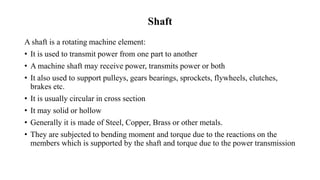
1. Shaft
A shaft is a rotating machine element:
• It is used to transmit power from one part to another
• A machine shaft may receive power, transmits power or both
• It also used to support pulleys, gears bearings, sprockets, flywheels, clutches,
brakes etc.
• It is usually circular in cross section
• It may solid or hollow
• Generally it is made of Steel, Copper, Brass or other metals.
• They are subjected to bending moment and torque due to the reactions on the
members which is supported by the shaft and torque due to the power transmission
2. Types of Shafts
Transmission Shaft
• These shafts may be stepped shafts which
are used for transmitting power between
one source to the other machine absorbing
power.
• On stepped portion of shaft gear, hub
or pulley are mounted for transferring
motion.
Axle Shaft
• These shafts supports rotating element
such as wheel and can fit in the housing
with bearing but the axle is a non rotating
element. These are mostly used in
vehicles. Example: Axle in automobiles.
3. Advantages of Shafts
• They are less likely to jam.
• They need less maintenance in comparison to chain system.
• They have high torsional strength.
• They have high value of polar moment of inertia.
• They are very strong and less likely to be failure.
• Internal shape of a hollow shaft is hollow therefore they require less material.
• Hollow shaft have low weight in comparison with solid shaft for same value of
torque transmission.
• They have high radius of gyration.
4. Disadvantages of Shafts
• Due to loose coupling they have power loss.
• They vibrated while rotation.
• They generate a constant noise.
• Manufacturing and maintenance costs are high.
• Difficult in manufacturing.
• Changing the speed of shaft is not easy.
• Due to mechanical problems the downtime is longer.
• Oil dripping from overhead shafting.
• Use of flexible couplings like leaf spring coupling can result in loss of velocity
between the shafts.
• If failure takes place in shafts then it takes huge time in repairing.
5. Shaft Standers& Design of Shaft
Transmission Shafts
25 mm to 60 mm 5 mm step
60 mm to 100 mm 10 mm step
110 mm to 140 mm 15 mm step
140 mm to 500 mm 20 mm step
Machine Shaft
Machines shaft’s standard sizes are up to 25 mm with 5 mm step. For shafts, the standard lengths
are 5m, 6m and 7m but generally taken as 1m to 2m.
Stresses in Shafts
• Stresses which are induced in shaft are:
• Shear stress which is induced because of the transmission of torque (torque induced due to the
torsional load).
• Bending stresses which is compressive or tensile in nature induced due to the forces which is
acting on the machine element such as pulleys and gear and from the self weight of shaft.
• Combined stress due to bending and torsional loads.
6. The Material Used For The Shafts
• The material used for ordinary shafts is mild steel.
• When high strength is required, alloy steel such as nickel, nickel-chromium,
or chromium-vanadium steel is used.
• The material used for the shafts must have the following properties:
• It should have high strength.
• It should have good mechanization.
• It should have a low-notch sensitivity factor.
• It should have good heat treatment properties.
• It should have high wear-resistant properties.
• The materials used for regular shafts are carbon steel of grade 40 C8, 45 C8,
50 C4, and 50 C12.
7. Manufacturing of Shafts
• Shafts are manufactured by hot rolling process. The strength of shaft is
higher in case of cold rolling in comparison with hot rolling but cold
rolling results in high residual stress which leads to the deformation of
shaft when machined.
• Forging process is used for the manufacturing of larger diameter
shafts.
• Dial gauge are used for checking the concentricity of shaft before
machining it and many operations such as turning, facing, grooving,
taper turning etc are performed according to the use.
• For achieving concentricity and roundness, the rotating tools should be
facing each other in centerline. Transmission shafts and motors are
usually made by this process.
8. Design of Shaft on the Basis of Strength & Rigidity
• Design of Shaft on the Basis of Strength
• Design of Shaft on the Basis of Rigidity Basis
Where,
• T = Torque or twisting moment in N – mm
• J = Polar moment of inertia = (π x D⁴)/ 32
•
• For Solid Shaft J= 𝜋
𝑑4
32
• For hollow shaft J= 𝜋(
𝑑𝑜4 −𝑑𝑖4
32
)
• D = Diameter of shaft in mm
• Ө = Angle of twist
• G = Modulus of rigidity in N/ mm²
9. • A shaft rotes a5 500 rpm, transmits power is 8kw. The ultimate shear
stress is 80 GPa. Determine minimum diameter to transmit the power
when the factor of safety is 2.
10. Shaft in Series
• If the shafts are in series having various diamemers for various pats of
length the
• T= T= T2=T3 etc.
• ϴ=ϴ1 +ϴ2+ϴ3 etc.