
Recommended
More Related Content
What's hot
What's hot (20)
Similar to CURRENT LIMITING REACTORS
Similar to CURRENT LIMITING REACTORS (20)
Recently uploaded
Recently uploaded (20)
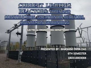
CURRENT LIMITING REACTORS
- 2. What is the Current Limiting Reactors? A current limiting reactor is an inductive coil having a large value of inductive reactance and is put in service for limiting during a fault condition. It is installed in feeders and short-circuit currents ties, in generator leads, and between the bus sections. Current reactor allows free interchange of power under normal condition, but when the fault occurs the disturbance is restricted by the current reactor to the faulty section. These are inserted in series with the line , to limit the current flow in the event of a short circuit.
- 3. Main Function It protects appliances from mechanical stress and overheating. current limiting reactor helps to minimize the magnitude of the disturbance voltage. The current limiting reactor helps in localizing the faults by limiting the current flowing into the faulty section from other healthy sections of the system. The current limiting reactor will reduce the required rating of the switching equipment (such as circuit breakers). Drawbacks When the reactor is installed on the network, the total percentage reactance of the circuit increases. It decreases the power factor and thus the regulation becomes poorer.
- 4. Construction of reactors The reactance of the reactor should not decrease under short circuit conditions. He reactor should be built with non magnetic cores or alternatively with an iron core but with air gap included in the magnetic circuit. To reduce losses in the reactor latter standard conductor is generally used. Total losses is of order of 5% of KVA rating of reactor. TYPES AND CONSTRUCTION OF CURRENT LIMITING REACTOR
- 5. The types of current limiting reactor are as follows: Bare type It consists of circular coils or bars of stranded coils installed in several specially designed concrete slabs.. A concrete base and porcelain post insulators provide the necessary insulation with the earth. This reactor is also known as dry type or concrete reactor. Cooling is done in these current limiting reactors by natural ventilation. For outdoor services, these reactors are unsuitable.We can use them for moderate voltages(up to 33KV) and power ratings. It is cheapest type of CLR and occupies large space. TYPES AND CONSTRUCTION OF CURRENT LIMITING REACTOR
- 6. Shielded or Oil-immersed Type : It consists of a cooling and insulation arrangement similar to that of an ordinary transformer. These reactors can be put into application for any voltage levels and outdoor and indoor applications. They have a smaller size in comparison to the dry-type reactors. It provides higher safety against flash-over and higher thermal capacity. This type of reactor has an air-cored or iron-cored construction. The iron-cored type has a saturation problem during short circuits. Cost of Oil immersed reactor will be considerably higher than of a Bare type. TYPES AND CONSTRUCTION OF CURRENT LIMITING REACTOR
- 7. Current Limiting Reactors are located at different location in a power system for reducing the short circuit current . Generator Reactor : Here we insert a current limiting reactor between the generator and the generator bus. These reactors protect the machines or the generators individually. (Fig A) With the installation of the new machine in the power system, we have to connect generator reactors for the old machines or generators. The magnitude of these reactors is 5 % or 0.05 per unit. The flow of full load current through these reactors during the normal operation causes a constant voltage drop and power loss. Fig A
- 8. Feeder Reactor We connect the feeder reactors in series with the feeder. During fault in any one of the feeders, the main voltage drop is in the reactor only thereby not affecting the bus bar considerably. (Fig B)Therefore other machines in the system can supply power to load continuously. When a fault occurs in any one of the feeders, the fault is localized such that other feeders are not affected. This reactor also introduces a constant voltage drop and power loss in the system. Fig B
- 9. Bus-Bar Reactor : Both the generator and feeder current limiting reactors introduces a constant voltage drop and power loss in the system. We can eliminate this problem by introducing reactors in the bus bar. There are two methods for this purpose, namely ; Ring system and Tie-Bar system. • (i) Ring system: In this system, bus-bar is divided into sections and these sections are connected through reactors . Generally, one feeder is fed from one generator only. Under normal operating conditions, each generator will supply its own section of the load and very little power will be fed by other generators This results in low power loss and voltage drop in the reactors. Fig C(1) • (ii) Tie-Bar system: This configuration of the current limiting reactor will improve the voltage regulation between the feeder sections. This system is suitable for the systems where generating systems are frequently added to the systems. In this system, the generator supplies power to the feeder directly and we connect generators to the common bus bar through the reactor. Fig C(2) Fig C(1) Fig C(2)
- 10. What is grounding? In power system grounding means connecting frame of electrical equipment(non current carrying part) or some electrical part of the system(e.g. neutral point in a star connected system) to earth i.e. soil. The primary goal of the grounding system throughout any facilities is safety. What is substation grounding? A substation grounding system has two main parts: the grounding network and the connection to the earth. The grounding network bonds all equipment frames and metallic structures in the substation, while the connection to the earth is the interface between the electrical system and the earth. There are three methods to connect a substation to the earth: radial, ring, and grid. The grid is the most effective system, although the most expensive. It is a lattice of copper conductors placed below grade and connected to the substation frame and equipment. The grid (earth mat)equalizes the surface potential gradients, protecting people and equipment.
- 11. The grounding system in substation is very important. The functions of grounding systems or earth mat in include: Provide the neutrals of generators, transformers, capacitors, and reactors a connection to the earth Offer a low impedance path to the earth for the currents coming from ground faults, lightning rods, surge arresters, gaps, and related devices Limit the potential differences that appear between the substation metallic objects or structures, and the ground potential rise (GPR), due to the flow of ground currents; they may pose a danger to equipment and personnel. Improve the operation of the protective relay scheme to clear ground faults Increase the reliability and availability of the electrical system Allow the grounding of de-energized equipment during maintenance. Earth Mat in 110kV side of a 220/110 kV Substation