This document provides an overview of material science and engineering concepts related to iron-carbon alloys, including:
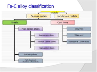
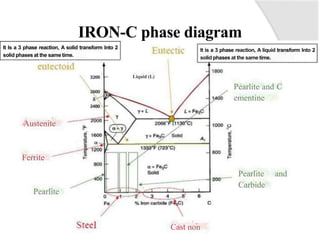
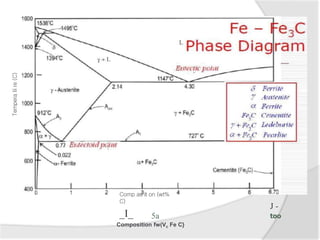
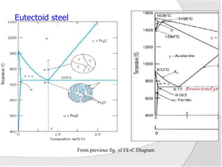
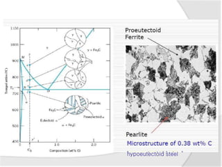
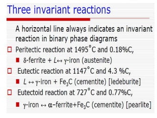
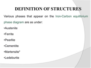
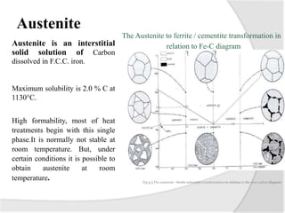
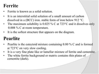
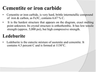
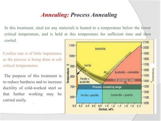
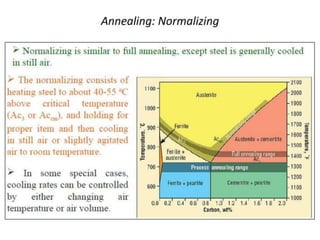
- The iron-carbon phase diagram, which shows the different phases that form based on carbon content and temperature. Key phases discussed include austenite, ferrite, pearlite, and cementite.
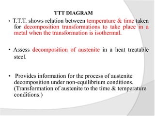
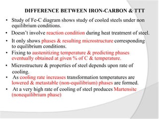
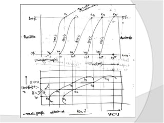
- The TTT (time-temperature-transformation) diagram, which shows the decomposition of austenite under non-equilibrium conditions based on time and temperature.
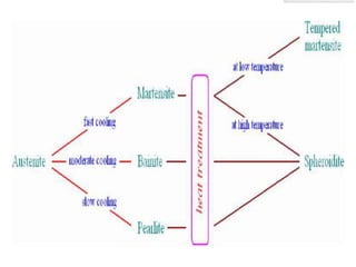
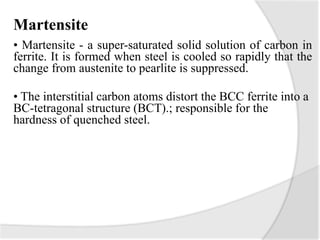
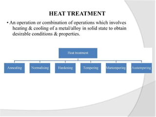
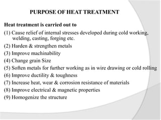
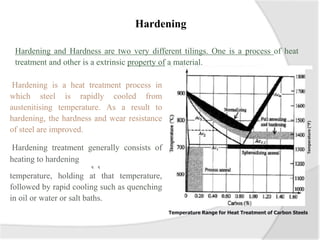
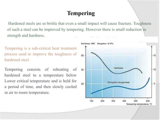
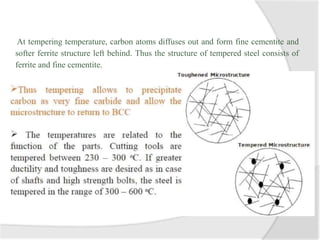
- Common heat treatment processes for steels like annealing, hardening, tempering, and their purposes. Hardening involves rapid cooling to form martensite for hardness while tempering reduces brittleness.