

Recommended
Recommended
More Related Content
What's hot
What's hot (20)
Similar to Juki RS-1R Catalog
Similar to Juki RS-1R Catalog (20)
More from Mark Tung
More from Mark Tung (20)
Recently uploaded
Recently uploaded (20)
Juki RS-1R Catalog
- 1. High-Speed Compact Modular Mounter Oct-2017/Rev.06 *Please refer to the product specifications for details. The RS-1 is an eco-friendly product which complies with JUKI ECO PRODUCTS standards for protecting the environment. ●The machine complies with the “JUKI Group Green Procurement Guidelines” on the use of hazardous substances, which is stricter than other restrictions, such as those of the RoHS Directive. For details of JUKI ECO PRODUCTS, refer to: http://www.JUKI.co.jp/eco_e/index.html *The RoHS Directive is an EU Directive limiting the use of 6 hazardous substances(lead, hexavalent chromium, mercury, cadmium,PBB and PBDE) in electrical and electronic equipment. The JUKI Green Procurement Guideline is the voluntarily established criteria to eliminate not only the aforementioned six substances, but also other ones which also adversely affect the environment. RS-1 website *1 For metric 0201 compliance please contact us. *2 Using RF feeders *3 D dimension does not include the front operation monitor. H dimension does not include signal tower. *4 Option except 200V ■Option ■Specification Model Item Component height Component size Placement speed Placement accuracy Feeder inputs Power supply Apparent power Operating air pressure Air consumption Machine dimensions (W×D×H) *3 Mass(approximately) Fast Smart Modular Mounter RS-1 Optimum IPC9850 650×370 ㎜ (Single clamping) 1,100×370 ㎜ (double clamping) 500×370 ㎜ 25 ㎜ 0201 *1 ~□74 ㎜ /50×150 ㎜ 42,000CPH 29,000CPH ±35µm(Cpk≧1) max.112 *2 AC200 ~ 415V *4 . 3-phases 2.2kVA 0.5±0.05MPa max.50L/min 1,800×1,810×1,440 ㎜ 約 1,700kg minimum maximum standard 150mm conveyor extensions, upstream and downstream 250mm conveyor extensions, upstream and downstream 50×50 ㎜ 950×370 ㎜ (double clamping) 360×370 ㎜ 1,200×370 ㎜ (double clamping) 600×370 ㎜ conveyor specification Board size 1,500×1,810×1,440 ㎜ 2,000×1,810×1,440 ㎜ 1 buffer 3 buffers *5 Please contact for details. *6 When EF feeders adapt the an attachment of EF feeder, the EF feeder can use on RF/EF feeder trolley and fixed bank (rear side). Please inquire details. *7 Separate connection cables for each model are required. Recognitions system Oparations system Inspection function Conveyor Electrical protection Force Control Software *5 Component handling and feeders Others 10 / 27/ 54 mm view camera Rear-side operation unit Coplanarity sensor / Component Verification System(CVS) *5 Conveyor extention/ support pin / support sponge CE compatible specification /Ground-fault interrupter Force control unit / Force control nozzle JaNets / IFS-NX / Flexline CAD Feeder Trolley (RF feeder only / RF-EF dual servo *6 ) /Electric tape feeder (RF/EF *7 ) /EF feeder adapter *6 / Electric stick feeder *7 (Type-N/Type-W) / Matrix tray server TR8SR , TR5SNX , TR5DNX / Matrix tray changer TR6SNV , TR6DNV / Dual tray server TR1RB /Nonstop oparation function/ Tray Holder / IC collection belt / Tape reel mounting base( for RF/ for EF) /Splicing jig /Electric Trolley Power Station PW02 *7 Nozzle /Splicing tape / Big foot / Offset placement after solder screen-printing Solder lighting www.smt11.com
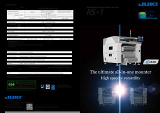
- 2. Feature5 驚異の汎用性Feature5 For products with a high number of small chip components, the RS-1 can function as a high speed machine. For products with a many large or odd-form parts, the RS-1 can run as a general purpose machine. The RS-1 is a true "all-in-one" machine that can handle a very wide range of PCB types in both high speed and flexible roles. Newly developed "Takumi Head" with changing recognition sensor heightFeature1 Feature2 Wide component range 0201 (metric) components supported New Dynamic Height 8 nozzle placement head automatically adjusts the centering laser height to optimize placement speed. This head adjusts automatically based on the production program from 1mm to 25mm tall components in 5 different positions. Optimal speed and component flexibility are possible without the need to change the head unit. component height PWB ex:component height 20mm Feature3 New vision recognition technology 【Variable height of the laser sensor in accordance with the component height】 Feature6 - Component polarity is detected and corrected automatically by the upward looking centering camera (VCS). - Upside down components Special algorithms can detect components that are upside down and reject them. - Small component handling Components down to 0201 (metric) are supported with the 10mm field of view camera option. The auto tape advance funciton reduces setup time by using the fiducial camera to advance new tapes to the first full pocket. Available for 8mm tape and components from 0402 (metric) to 3216. OCC 先頭部品の頭出し Feature4 Auto tape advance function 25㎜ 1㎜ 6㎜ 12㎜ 20㎜ 360-degree component recognition image Changing the RS-1 functionality does not require head replacement. The revolutionary design adapts to the production requirements automatically. It can be used in-line with high speed chip placement machines to improve overall line productivity or to make the line more flexible for complex PCBs with a high number of large components. Optimum line balance and highest throughput The RS-1 can change its function dynamically from high speed chip placement to flexible placement of large components. This improves optimization and line balancing for various products. 【Without RS-1】 【With RS-1】 Example PWB with 1000 chips, 50 large components. 【Without RS-1】 【With RS-1】 chip mounter Flexible mounter The flexible design for the RS-1 means it can adjust for smaller components and maintain high speed placement capability. Products with a high number of large components increase the load on the flexible machine, making it a bottleneck. Case Study 1 Case Study 2 Case Study 3 Products with a high percentage of small chips results in poor utilization of flexible machines. chip mounter chip mounterchip mounter Flexible mounter chip mounter chip mounterchip mounter Flexible mounter The RS-1 automatically adjusts its component capability making it possible to balance the load across several machines and reducing bottlenecks. Example PWB with 300 chips, 100 large components. Class leading speed, up to 42,000 cph Maximum speed of up to 42,000 cph*. This is made possible by a revolutionary head design that reduces the travel time and distance for every placement. The new RF feeders are smaller and lighter, but still maintain the same high degree of positional accuracy. The thinner width allows up to 112 feeder inputs.* New RF feeders are smaller, thinner, and lighter * Total for front and rear 42,000CPH Comparison to conventional machine 179% 23,500CPH *2 Optimum 【Placement speed *2 】 RS-1Conventional machine *1 *1 KE-3010A 112 units *2 Total for front and rear Comparison to conventional machine 140% 80 units 【Maximum number of feeders mounted *2 】 RS-1 *1 KE-3010A Conventional machine *1 * Optimum Class leading speed, up to 42,000 cph Line Balancer ex:component height 6mm RS-1 supports components from 0201*1(metric) up to 74mm square or 50x150 retangular parts. Component height up to 25mm. Wide component range *1 Please contact for details. □33.5□20 0201 0603 1005 1608 AL CN SOT SOP QFN QFP Card Slot Big AL CN DI ㎜ CN Lead Long CN BGA FBGA Big QFP □50 RS-1 component range 0402 Conventional machine*2 component range □74 Component density Advancedfunctionality 0201 *2 ~ 74 ㎜、 50×150 ㎜ 0402 ~ □33.5 ㎜ *2 Please contact for details. 【Part correspondence power】 RS-1 *1 KE-3010A Conventional machine*1 *2 KE-3010A
- 3. 8 placement nozzles can pick and center on-the-fly for high speed production Component centering is performed on-the-fly during the movement from the pick to the placement position using a laser unit built onto the head. High speed placement is possible by eliminating travel to a centering camera. Component shape, lead and ball details are accurately captured using our VCS camera. Component problems such as missing ball detection or bent leads are also detected. A wide variety of com- ponents including BGAs and QFPs and many more are supported. - Three color illumination Optimal lighting color is used to accurately center different compo- nent types. - Wide component range A wide variety of components, including odd-form parts that require special nozzles, can be centered precisely - Improved centering speed A new VCS unit can center up to 4 parts in a single image, reducing centering time by 25% with the 54mm field of view VCS. The 10mm and 27mm field of view cameras also support high speed centering and multi-imaging or larger components. 反射認識 反射認識 透過認識 A wide component range is available including parts as small as 03015 (metric), PLCCs, SOPs, QFPs and larger parts up to 50mm square. Laser centering is accurate, fast, and is not affected by variations in components such as lead brightness shape. JUKI's proprietary laser recognition technology is flexible, accurate and reliable. Image recognition technology Bank specification can be selected Feeder banks are available in either fixed or easy to replace trolley configurations. image Laser ■fixed bank specification □exchange truck specificationfront rear Tray component feeding Tray parts can be supplied in a variety of tray chang- ers and single tray holders. The compact TR8SR presents the trays for direct picking by the placement head and leaves 20 8mm tape feeder slots free on the rear side. The shuttle type tray changer, TR6, uses no feeder space and includes a conveyor that can be used for inspection. With the rear operation unit, better operator efficiency is possible. TR8SR mounting image Rear operation unit The path from picking to centering and placement is optimized for the fastest possible production speed. *Please contact for detail. 【Multi-component centering】 Up to 4 components are centered in a single image Sample components and images image of laser recognition Automated pre-production check list Operators can use the automated pre-production check list to make sure all required operations have been completed. Ensures consistency and reduces overlooked operations. Setup preparation menu The feeder pick position is automatically adjusted based on centering results to improve simultaneous picking and increasing throughput. Feeder pick position auto-correct Pick Position Auto-correction standard ※KE-3010A Sample images Laser Laser standardoption Flexible vision teaching Complicated programming of odd-shaped compo- nents is made easier by following step-by-step guidelines, reducing programming time significantly. Flexible vision teaching Ease-of-operation improved by automatic component measurement Component data can be programmed simply by typing approximate dimensions, type and packaging informa- tion. Accurate dimensions, number of leads and lead pitch are measured and programmed automatically by the machine. Component data is updated after automatic measurement. Component dimensions: Width Depth Height ②Component state check Compare the dimensions and ratio of component data to the component picked for confirmation of pick orientation. ③Component dimension check Compare the dimensions of the part picked to the component data to ensure the right part is picked. ④Component fall check Laser checks if the component falls before placement. ⑤Release check Laser checks if the component is properly released on the board after placement. The component check function improves the quality of component placement. Component presence is monitored by the laser from pick to placement, reducing the chance for missing components. The component check function improves the quality of component placement. Laser Laser ①On-the -fly component detection Laser detects presence of components. Laser Recognition algorithm Laser calculates the following data for each component: component shape Center Angle Width Laser sensor integrated into placement head standard standard option
- 4. Coplanarity sensor - checks balls and leads Mini-signal light JUKI's highly regarded easy maintenance just got even easier! The optional FCS calibration jig is a simple to use system to re-calibrate placement accuracy. The machine automatically picks and places jig components, then measures the error and adjusts all necessary calibrations. (optional) The IC collection belt The IC collection belt provides a safe method to handle rejected parts while also protecting them from further damage. Belt pitch can be set for different size parts. The mini signal light clearly shows operators which side of the machine has an empty feeder. Mini Signal Light Pick and placement force can be precisely controlled using the load cell option. The force for each nozzle is measured and applied during pick and placement to reduce the possibility of damaging sensitive components. Placement force control with Load cell option Load cell data display Laser condition check Dirty laser, low vacuum and upward looking camera condition are all checked prior to production starting to warn the operator of potential problems and prevent defects. The IC collection belt FCS image Soft under board support reduces defects caused by PCB warpage. This unit uses soft pillars that will not damage components on the bottom side and do not require setup for each different PCB. They are easy to removed with a simple magnetic base. Support sponge Capable of long board production It can be standardized up to 650 mm × 370 mm with one clamp and 950 × 370 mm with 2 clamps. Furthermore, by combining optional transport extension, it is possible to handle long board production up to 1,200 mm × 370 mm. ●Solder paste for fiducials Solder printed pads can be used in place of fiducials for circuit boards that do not have fiducials. This is especially helpful on long PCBs that require double clamping and do not have a fiducial in the appro- priate area. Dual Tray Server TR1RB The dual tray server (DTS) reduces the tray replacement time by 75% compared to a standard tray holder. It also leaves space for tape feeders on the feeder bank. The new DTS is 26% lighter than previous models to make changeover even easier. Feeder Setup Stand The feeder setup fixture is used to load reels offline quickly and easily. It is safer and easier to use than laying feeders on a table. Proactive maintenance warnings support sponge Feeder Setup Fixture for RF feeder TR1RB The OPASS function uses the machine's downward looking camera to check the location of solder paste vs. the pads and corrects the placement accordingly. This function reduces defects caused by misalignment of the paste on the pads. Reduce errors due to solder paste alignment Offset Placement After Solder Screen printing Incorrect component prevention Component Verification System (CVS) By measuring the resistance, capacitance, or polarity before production starts, the machine can prevent incorrect components from being placed. The new CVS unit can check six components simultaneously, reducing the check and changeover times. Electrodes (A) used to check polarity or measure components Check the Resistance,Capacitance and Polarity before production starts. Prevents incorrect component/reel from being used Prevents incorrect component placement Solder Pad [A printing misalignment occurs] With OPASS function Without OPASS function Placement based on solder location Placement based on pad location Reduction in the percentage defective Prevents placement of defective component by checking lead float of lead component and nick of ball compo- nent. High accurate and high speed coplanarity check will improve the products' reliability. Laser direction Component direction Coplanarity sensor BGA ball defect Lead float defect option option standard option option option option optionoption option option optionoption FCS (Flex Calibration System) Non-stop Operation Non-stop operation allows the operator to replace feeders while the machine continues to run at full speed.