Isweek pid a12 photo ionisation detector
•
0 likes•49 views

Photo Ionisation Detector - PID-A12 http://www.isweek.com/product/pid-a12-photo-ionisation-detector-pid-a12_20.html

Recommended
More Related Content
What's hot
What's hot (20)
Viewers also liked
Viewers also liked (16)
Similar to Isweek pid a12 photo ionisation detector
Similar to Isweek pid a12 photo ionisation detector (20)
Recently uploaded
Recently uploaded (20)
Isweek pid a12 photo ionisation detector
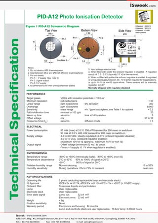
- 1. TTTTTececececechnicalSpecifhnicalSpecifhnicalSpecifhnicalSpecifhnicalSpecificaicaicaicaicationtiontiontiontion PID-A12PID-A12PID-A12PID-A12PID-A12 Photo Ionisation Detector Figure 1 PID-A12 Schematic Diagram US patent 7,046,012 US patent 7,821,270 EU patent 1474681 Other patents PERFORMANCE Target gases VOCs with ionisation potentials < 10.6 eV Minimum resolution ppb isobutylene < 50 Linear range ppm isobutylene 5% deviation 300 Overrange ppm isobutylene 6,000 Sensitivity linear range mV / ppm Isobutylene, see Table 1 for options > 0.3 Full stabilisation time minutes to 100 ppb 20 Warm up time seconds time to full operation 5 Offset voltage mV 50 to 59 Response time (t90 ) seconds diffusion mode < 3 ELECTRICAL Power consumption 85 mW (max) at 3.2 V, 350 mW transient for 200 msec on switch-on 90 mW at 3.3 V, 460 mW transient for 200 msec on switch-on Supply voltage 3.2 to 3.6 VDC Ideally regulated ±0.01V (onboard regulator disabled) 3.6 to 10 VDC (onboard regulator enabled) (maximum 10V for IS approval, maximum 18 V for non-IS) Output signal Offset voltage (minimum 50 mV) to Vmax (Vmax = Vsupply -0.1 V when regulator is enabled) ENVIRONMENTAL Temperature range -40ºC to +55ºC(Intrinsically Safe); -40ºC to +65ºC (non-IS) Temperature dependence 0°C to 40°C 90% to 100% of signal at 20°C -20°C 140% of signal at 20°C Relative humidity range Non-condensing 0 to 95% Humidity sensitivity During operations: 0% to 75% rh transient near zero KEY SPECIFICATIONS Operating life 5 years (excluding replaceable lamp and electrode stack) IS Approval IECEx Ex ia IIC T4; ATEX Ex ia II 1G -40ºC < Ta < +55ºC (< 10VDC supply) Onboard filter To remove liquids and particulates Lamp User replaceable Electrode stack User replaceable Error state signal Lamp out: 32 ±4 mV Electronic error: 22 ±6 mV Weight < 8g Position sensitivity None Warranty period Electronics and housing: 24 months Lamp and electrode stack are user replaceable. 10.6eV lamp: 5,000 lit hours Notes: 1. Do not obstruct Ø3.5 sensing area 2. Seal between Ø6.2 and Ø9.0 (if different to atmosphere) 3. Pin out details: . Pin 1: + V supply (See note 5) Pin 2: Signal output Pin 3: 0 V supply 4. All dimensions ±0.1mm unless otherwise stated 5. Input voltage selector hole: a) When filled with solder the onboard regulator is disabled. A regulated supply of 3.2 - 3.6 V (typically 3.2 V) is then required. b) When not filled with solder the onboard regulator is enabled.A regulated or unregulated supply between 3.6 - 10 V is then required for IS applications, or up to 18 V for non-IS applications. These sensors will be internally regulated to 3.3V Normally shipped with regulator disabled.
- 2. 70 80 90 100 110 120 130 140 -30 -20 -10 0 10 20 30 40 50 0 500 1000 1500 2000 2500 3000 0 1000 2000 3000 4000 5000 TTTTTececececechnicalSpecifhnicalSpecifhnicalSpecifhnicalSpecifhnicalSpecificaicaicaicaicationtiontiontiontion PID-A12 PPID-A12 PPID-A12 PPID-A12 PPID-A12 Perferferferferformance Daormance Daormance Daormance Daormance Datatatatata In the interest of continued product improvement, we reserve the right to change design features and specifications without prior notification. The data contained in this document is for guidance only. Alphasense Ltd accepts no liability for any consequential losses, injury or damage resulting from the use of this document or the information contained within. ( ©ALPHASENSE LTD ) Doc. Ref. PID-A12/JUL16 For further information on the performance of this sensor, on other sensors in the range or any other subject, please contact Alphasense Ltd. For Application Notes visit “ Figure 2 Sensitivity Temperature Dependence Figure 3 Linearity to Isobutylene Figure 2 shows the temperature dependence, corrected for the gas law. This data is taken from a typical batch of PID-A12 sensors tested with 100ppm Isobutylene. The mean and ±95% confidence intervals are shown. Isobutylene (ppm) Output(mV)%Output(referencedto20o C) Temperature (o C) At the end of the product’s life, do not dispose of any electronic sensor, component or instrument in the domestic waste, but contact the instrument manufacturer, Alphasense or its distributor for disposal instructions. Table 1: PID Replaceable Parts/Consumables List PID output is non-linear at higher concentrations but is repeatable and can be corrected in software. Non-linearity correction depends on the VOC being measured. NOTE: all sensors are tested at ambient environmental conditions, unless otherwise stated. As applications of use are outside our control, the information provided is given without legal responsibility. Customers should test under their own conditions, to ensure that the sensors are suitable for their own requirements. Lamp type Product code Minimum sensitivity mV/ppm Minimum range ppm isobutylene Lamp life lit hours 10.0 eV 001-0030-02 0.2 9000 5000 10.6 eV (HPPM) 001-0019-04 0.3 6000 2000 10.6 eV (LLHS) 001-0030-01 0.8 2000 5000 11.7 eV 001-0019-03 24 Electrode stack 001-0018-02 Stack removal tool 001-0020-00 Lamp spring 001-0023-00 Lamp cleaning kit 001-0024-00