1. LiquidPenetrantTesting Page 1 of 20
Liquid Penetrant Testing
Liquid penetrant testing is oneof the oldestand simplestNDTmethodswhereits earliest
versions (using kerosene and oil mixture) dates back to the 19th
century. This method is
used to reveal surfacediscontinuities by bleed out of a colored or fluorescent dye from
the flaw. The technique is based on the ability
of a liquid to be drawn into a "clean" surfacediscontinuity
by capillary action. After a period of time called the "dwell
time", excess surface penetrant is removed and a
developer applied. This acts as a blotter that draws the
penetrant from the discontinuity to reveal its presence.
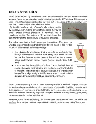
The advantage that a liquid penetrant inspection offers over an
unaided visual inspection is that it makes defects easier to see for the
inspector where that is done in two ways:
It produces a flaw indication that is much larger and easier for
the eye to detect than the flaw itself. Many flaws areso small or
narrow that they are undetectable by the unaided eye (a person
with a perfect vision cannot resolve features smaller than 0.08
mm).
It improves the detectability of a flaw due to the high level of
contrastbetween the indication and the background which helps
to make the indication more easily seen (such as a red indication
on a white background for visable penetrantor a penetrantthat
glows under ultraviolate light for flourecent penetrant).
Liquid penetrant testing is one of the most widely used NDTmethods. Its popularity can
be attributed to two main factors:its relative ease of useand its flexibility. Itcan be used
to inspectalmostanymaterial providedthat its surfaceis notextremely roughorporous.
Materials that are commonly inspected using this method include; metals, glass, many
ceramic materials, rubber and plastics.
However, liquid penetrant testing can only be used to inspect for flaws that break the
surfaceof the sample (such as surface cracks, porosity, laps, seams, lack of fusion, etc.).
2. LiquidPenetrantTesting Page 2 of 20
Steps of Liquid Penetrant Testing
The exact procedure for liquid penetrant testing can vary from case to case depending
on severalfactors such as the penetrant systembeing used, the size and material of the
component being inspected, the type of discontinuities being expected in the
component and the condition and environment under which the inspection is
performed. However, the general steps can be summarized as follows:
1. Surface Preparation: Oneof the most critical steps of a liquid penetrant testing is
the surfacepreparation. The surface must be free of oil, grease, water, or other
contaminants that may prevent penetrant from entering flaws. The sample may
also require etching if mechanical operations such as machining, sanding, or grit
blasting have been performed. Theseand other mechanical operations can smear
metal over the flaw opening and prevent the penetrant from entering.
2. PenetrantApplication: Once the surface has been thoroughly cleaned and dried,
the penetrant material is applied by spraying, brushing, or immersing the part in
a penetrant bath.
3. PenetrantDwell: The penetrant is left on the surfacefor a sufficient time to allow
as much penetrant as possible to be drawn or to seep into a defect. Penetrant
dwell time is the total time that the penetrant is in contact with the part surface.
Dwell times are usually recommended by the penetrant producers or required by
the specification being
followed. The times vary depending on
the application, penetrant materials
used, the material, the form of the
material being inspected, and the type
of discontinuity being inspected for.
Minimum dwell times typically range
from 5 to 60 minutes. Generally, there
is no harm in using a longer penetrant dwell time as long as the penetrant is not
allowed to dry. The ideal dwell time is often determined by experimentation and
may be very specific to a particular application.
4. Excess Penetrant Removal: This is the most delicate step of the inspection
procedure because the excess penetrant must be removed from the surface of
the sample while removing as little penetrant as possible from defects.
3. LiquidPenetrantTesting Page 3 of 20
Depending on the penetrant system
used, this step may involve cleaning
with a solvent, direct rinsing with
water, or first treating the part with an
emulsifier and then rinsing with water.
5. Developer Application: A thin layer of developer is then applied to the sample to
draw penetrant trapped in flaws back to the surface where it will be visible.
Developers come in a variety of forms that may be applied by dusting (dry
powders), dipping, or spraying (wet developers).
6. Indication Development: The
developer is allowed to stand on the
part surface for a period of time
sufficient to permit the extraction of
the trapped penetrant out of any
surfaceflaws. This development time
is usually a minimum of 10 minutes.
Significantly longer times may be
necessary for tight cracks.
7. Inspection: Inspection is then performed under appropriate lighting to detect
indications from any flaws which may be present.
8. Clean Surface: Thefinal step in the process is to thoroughly clean the part surface
to remove the developer from the parts that were found to be acceptable.
Advantages and Disadvantages
The primary advantages and disadvantages when compared to other NDT methods
are:
Advantages
High sensitivity (small discontinuities can be detected).
4. LiquidPenetrantTesting Page 4 of 20
Few material limitations (metallic and nonmetallic, magnetic and nonmagnetic,
and conductive and nonconductive materialsmay be inspected).
Rapid inspection of large areas and volumes.
Suitable for parts with complex shapes.
Indications areproduced directly on the surfaceof the partand constitute a visual
representation of the flaw.
Portable (materials are available in aerosolspray cans)
Low cost (materials and associated equipment are relatively inexpensive)
Disadvantages
Only surfacebreaking defects can be detected.
Only materials with a relatively nonporous surfacecan be inspected.
Pre-cleaning is critical since contaminants can maskdefects.
Metal smearing frommachining, grinding, and grit or vapor blasting mustbe
removed.
The inspector musthave direct access to the surfacebeing inspected.
Surfacefinish and roughness can affect inspection sensitivity.
Multiple process operations mustbe performed and controlled.
Postcleaning of acceptable parts or materials is required.
Chemical handling and proper disposalis required.
Penetrants
Penetrants are carefully formulated to producethe level of sensitivity desired by the
inspector. The penetrant mustpossess a number of important characteristics:
- spread easily over the surfaceof the material being inspected to provide
complete and even coverage.
- be drawn into surfacebreaking defects by capillary action.
- remain in the defect but remove easily fromthe surfaceof the part.
- remain fluid so it can be drawn back to the surfaceof the part through the
drying and developing steps.
- be highly visible or fluoresce brightly to produce easy to see indications.
- not be harmful to the material being tested or the inspector.
5. LiquidPenetrantTesting Page 5 of 20
Penetrant materials are not designed to perform the same. Penetrant manufactures
have developed different formulations to address a variety of inspection applications.
Some applications call for the detection of the smallest defects possible while in other
applications, the rejectable defect size may be larger. The penetrants that are used to
detect the smallestdefects will alsoproducethe largestamountof irrelevant indications.
Standard specifications classify penetrant materials according to their physical
characteristics and their performance.
Penetrant materials come in two basic types:
Type 1 - Fluorescent Penetrants: they contain a dye or several dyes that fluoresce
when exposed to ultraviolet radiation.
Type 2 - Visible Penetrants: they contain a red dye that provides high contrast
against the white developer background.
Fluorescent penetrant systems are more sensitive than visible penetrant systems
becausethe eye is drawn to the glow of the fluorescing indication. However, visible
penetrants do not requirea darkened area and an ultraviolet light in order to make
an inspection.
Penetrants are then classified by the method used to remove the excess penetrant
fromthe part. The four methods are:
Method A - Water Washable: penetrants can be removed fromthe part by rinsing
with water alone. These penetrants contain an emulsifying agent (detergent) that
makes it possible to wash the penetrant from the part surface with water alone.
Water washablepenetrants are sometimes referred to as self-emulsifying systems.
Method B - Post-Emulsifiable, Lipophilic: the penetrant is oil soluble and interacts
with the oil-based emulsifier to make removal possible.
Method C - Solvent Removable: they require the use of a solvent to remove the
penetrant from the part.
Method D - Post-Emulsifiable, Hydrophilic: they use an emulsifier that is a water-
solubledetergent which lifts the excess penetrant fromthe surfaceof the partwith
a water wash.
6. LiquidPenetrantTesting Page 6 of 20
Penetrants arethen classified based on the strength or detectability of the indication
that is produced for a number of very small and tight fatigue cracks. The five
sensitivity levels are:
Level ½ - Ultra Low Sensitivity
Level 1 - Low Sensitivity
Level 2 - MediumSensitivity
Level 3 - High Sensitivity
Level 4 - Ultra-High Sensitivity
The procedure for classifying penetrants into one of the five sensitivity levels uses
specimens with small surface fatigue cracks. The brightness of the indication
produced is measured using a photometer.
Developers
The role of the developer is to pull the trapped penetrant material out of defects and
spread it out on the surface of the part so it can be seen by an inspector. Developers
used with visible penetrants create a white background so there is a greater degree of
contrast between the indication and the surrounding background. On the other hand,
developers used with fluorescent penetrants both reflect and refract the incident
ultravioletlight, allowingmoreof it to interactwith the penetrant, causingmoreefficient
fluorescence.
According to standards, developers are classified based on the method that the
developer is applied (as a dry powder, or dissolved or suspended in a liquid carrier). The
six standard forms of developers are:
Form a - Dry Powder
Formb - Water Soluble
Form c - Water Suspendable
Formd - Nonaqueous Type 1:Fluorescent (Solvent Based)
Form e - Nonaqueous Type 2: Visible Dye (Solvent Based)
Form f - Special Applications
7. LiquidPenetrantTesting Page 7 of 20
Dry Powder
Dry powder developers are generally considered to be the least sensitive but they are
inexpensive to use and easy to apply. Dry developers are white, fluffy powders that can
be applied to a thoroughly dry surface in a number of ways; by dipping parts in a
container of developer, by using a puffer to dust parts with the developer, or placing
parts in a dust cabinet where the developer is blown around. Since the powder only
sticks to areas of indications since they arewet, powder developers areseldomused for
visible inspections.
Water Soluble
As the name implies, water soluble developers consistof a group of chemicals that are
dissolved in water and form a developer layer when the water is evaporated away. The
bestmethod for applying water solubledevelopers is by spraying iton the part. The part
can be wet or dry. Dipping, pouring, or brushing the solution on to the surface is
sometimes used butthese methods are less desirable. Drying is achieved by placing the
wet, but well drained part, in a recirculating warmair dryer with a temperature of 21°C.
Properly developed parts will have an even, light white coating over the entire surface.
Water Suspendable
Water suspendable developers consist of insoluble developer particles suspended in
water. Water suspendabledevelopers require frequent stirring or agitation to keep the
particles from settling out of suspension. Water suspendable developers are applied to
parts in the same manner as water soluble developers then the parts are dried using
warm air.
Nonaqueous
Nonaqueous developers suspend the developer in a volatile solvent and are typically
applied with a spray gun. Nonaqueous developers are commonly distributed in aerosol
spray cans for portability. The solvent tends to pull penetrant from the indications by
solvent action. Since the solvent is highly volatile, forced drying is not required.
Special Applications
Plastic or lacquer developers are special developers that are primarily used when a
permanent record of the inspection is required.
8. LiquidPenetrantTesting Page 8 of 20
Preparation of Part
One of the most critical steps in the penetrant inspection process is preparing the part
for inspection. All coatings, such as paints, varnishes, plating, and heavy oxides must be
removed to ensure that defects are open to the surface of the part. If the parts have
been machined, sanded, or blasted prior to the penetrant inspection, it is possible that
a thin layer of metal may have smeared across the surfaceand closed off defects. Also,
some cleaning operations, such as steam cleaning, can cause metal smearing in softer
materials. This layer of metal smearing must be removed before inspection.
Penetrant Application and Dwell Time
The penetrant material can be applied in a number of different
ways, including spraying, brushing, or immersing the parts in a
penetrant bath. Once the partis covered with penetrant it must be
allowed to dwell so the penetrant has time to enter any defect that
is present.
There are basically two dwell mode options:
- Immersion-dwell: keeping the part immersed in the penetrant
during the dwell period.
- Drain-dwell: letting the partdrain during the dwell period
(this method gives better sensitivity).
Penetrant Dwell Time
Penetrant dwell time is the total time that the penetrant is in contact with the part
surface. The dwell time is important because it allows the penetrant the time necessary
to seep or be drawn into a defect. Dwell times are usually recommended by the
penetrant producers or required by the specification being followed. The time required
to fill a flaw depends on a number of variables which include:
The surfacetension of the penetrant.
The contact angle of the penetrant.
The dynamic shear viscosity of the penetrant.
The atmospheric pressureatthe flaw opening.
The capillary pressureat the flaw opening.
The pressureof the gas trapped in the flaw by the penetrant.
9. LiquidPenetrantTesting Page 9 of 20
The radius of the flaw or the distance between the flaw walls.
The density or specific gravity of the penetrant.
Microstructuralproperties of the penetrant.
The ideal dwell time is often determined by experimentation and is often very specific
to a particular application. For example, the table shows the dwell time requirements
for steel parts according to some of the commonly used specifications.
Penetrant Removal Process
The penetrant removal procedure must effectively remove the penetrant from the
surface of the part without removing an appreciable amount of entrapped penetrant
fromthe discontinuity. If theremovalprocess extracts penetrantfromtheflaw, the flaw
indication will be reduced by a proportional amount. If the penetrant is not effectively
removed fromthe partsurface,thecontrastbetween the indication and thebackground
will be reduced.
Removal Method
As mentioned previously, penetrantsystems areclassified into four categories
according to the method used for excess penetrant removal.
- Method A: Water-Washable
- Method B: Post-Emulsifiable, Lipophilic
- Method C: Solvent Removable
- Method D: Post-Emulsifiable, Hydrophilic
10. LiquidPenetrantTesting Page 10 of 20
Method C, SolventRemovable, is used primarilyfor inspecting small localized areas. This
method requires hand wiping the surface with a cloth moistened with the solvent
remover, and is, therefore, too labor intensive for most production situations.
Method A, Water-Washable, is the most economical to apply of the different methods
and it is easy to use. Water-washable or self-emulsifiable penetrants contain an
emulsifier as an integral partof the formulation. The excess penetrant may be removed
from the object surface with a simple water rinse.
When removal of the penetrant from the defect due to over-washing of the part is a
concern, a post-emulsifiable penetrant system can be used. The post-emulsifiable
methods aregenerally only used when very high sensitivity is needed. Post- emulsifiable
penetrants requirea separateemulsifier to breakdown thepenetrant and make it water
washable. Thepartis usually immersed in the emulsifier but hydrophilic emulsifiers may
also be sprayed on the object. Brushing the emulsifier on to the part is not
recommended because the bristles of the brush may force emulsifier into
discontinuities, causing the entrapped penetrant to be removed. The emulsifier is
allowed sufficient time to react with the penetrant on the surface of the part but not
given time to makeits way into defects to react with the trapped penetrant. Controlling
the reaction time is of essential importance when using a post-emulsifiable system. If
the emulsification time is too short, an excessiveamountof penetrant will be left on the
surface, leading to high background levels. If the emulsification time is too long, the
emulsifier will react with the penetrant entrapped in discontinuities, making it possible
to deplete the amount needed to form an indication.
The hydrophilic post-emulsifiablemethod (Method D) is gives better sensitivity than the
lipophilic post-emulsifiable method (Method B). The major advantage of hydrophilic
emulsifiers is that they are less sensitive to variation in the contact and removal time.
When a post-emulsifiable penetrant is used, the penetrant inspection process includes
the followingsteps (extrasteps areunderlined):1.pre-clean part, 2.apply penetrant and
allow to dwell, 3. pre-rinse to remove first layer of penetrant, 4. apply hydrophilic
emulsifier and allow contact for specified time, 5. rinse to remove excess penetrant, 6.
dry part, 7. apply developer and allow part to develop, and 8. inspect.
Rinse Method and Time for Water-Washable Penetrants
The method used to rinsethe excess penetrant fromthe object surfaceand the time of
the rinse should be controlled so as to prevent over-washing. It is generally
recommended that a coarse spray rinse or an air-agitated, immersion wash tank be
11. LiquidPenetrantTesting Page 11 of 20
used. When a spray is being used, it should be directed at a 45°angle to the part surface
so as to not forcewater directly into any discontinuities that may be present. The spray
or immersion time should be kept to a minimum through frequent inspections of the
remaining background level.
Hand Wiping of Solvent Removable Penetrants
When a solvent removable penetrant is used, care must also be taken to carefully
removethe penetrantfromthe partsurfacewhileremoving as little as possiblefromthe
flaw. The firststep in this cleaning procedureis to drywipe the surfaceof the part in one
direction using a white, lint-free, cotton rag. One dry pass in one direction is all that
should be used to remove as much penetrant as possible. Next, the surface should be
wiped with one pass in one direction with a rag moistened with cleaner. One dry pass
followed by one damp pass is all that is recommended. Additional wiping may
sometimes be necessary; butkeep in mind that with every additional wipe, someof the
entrapped penetrant will be removed and inspection sensitivity will bereduced.
Use and Selection of a Developer
The use of developer is almost always recommended. The output from a fluorescent
penetrant is improved significantly when a suitable powder developer is used. Also, the
use of developer can have a dramatic effect on the probability of detection of an
inspection.
Nonaqueous developers are generally recognized as the most sensitive when properly
applied. However, if the thickness of the coating becomes too great, defects can be
masked. Therelative sensitivities of developers and application techniques as ranked in
Volume II of the Nondestructive Testing Handbook are shown in the tablebelow.
Ranking Developer Form Method of Application
1 Nonaqueous, Wet Solvent Spray
2 Plastic Film Spray
3 Water-Soluble Spray
4 Water-Suspendable Spray
5 Water-Soluble Immersion
6 Water-Suspendable Immersion
7 Dry Dust Cloud (Electrostatic)
8 Dry Fluidized Bed
9 Dry Dust Cloud (Air Agitation)
10 Dry Immersion (Dip)
12. LiquidPenetrantTesting Page 12 of 20
The following table lists the main advantages and disadvantages of the various
developer types.
Developer Advantages Disadvantages
Soluble Ease of coating entire part Coating is translucent and
provides poor contrast (not
recommended for visable
systems)
Indications for water
washable systems are dim
and blurred
Suspendable Ease of coating entire part
Indications are bright and
sharp
White coating of good
contrast can be produced
which work well for both
visible and fluorescent
systems
Nonaqueous Very portable
Easy to apply to readily
accessible surfaces
White coating of good
contrast can be produced
which work well for both
visible and fluorescent
systems
Indications show-up rapidly
and are well defined
Indications weaken and
become diffused after time
Difficult to apply evenly to
all surfaces
More difficult to clean part
after inspection
Provides highest sensitivity
Dry Indications tend to remain
brighter and more distinct
over time
Does not form contrast
background so cannot be
used with visible systems
Easy to apply Difficult to assure entire part
surface has been coated
13. LiquidPenetrantTesting Page 13 of 20
Quality & Process Control
Quality control of the penetrant inspection process is essential to get good and
consistent results. Since several steps and materials are involved in the inspection
process, there are quality control procedures for each of them.
Temperature Control
The temperature of the penetrant materials and the part being inspected can have an
effect on the results. Temperatures from 27 to 49°C are reported in the literature to
produce optimal results. Many specifications allow testing in the range of 4 to 52°C.
Raising the temperature beyond this level will significantly raise the speed of
evaporation of penetrants causing them to dry out quickly.
Since the surface tension of most materials decrease as the temperature increases,
raising the temperatureof the penetrant will increasethe wetting of the surfaceand the
capillary forces. Of course, the opposite is also true, so lowering the temperature will
have a negative effect on the flow characteristics.
Penetrant Quality Control
The quality of a penetrantinspection is highly dependent on the quality of the penetrant
materials used. Only products meeting the requirements of an industry specification,
such as AMS 2644, should be used. Deterioration of new penetrants primarily results
fromaging and contamination. Virtually all organic dyes deteriorate over time, resulting
in a loss of color or fluorescent response, but deterioration can be slowed with proper
storage. When possible, keep the materials in a closed container and protect from
freezing and exposure to high heat.
Contamination can occurduring storageand use.Ofcourse,open tank systemsaremuch
more susceptible to contamination than are spray systems. Regular checks must be
performed to ensure that the material performance has not degraded. When the
penetrant is firstreceived fromthe manufacturer, a sample of the fresh solution should
be collected and stored as a standard for future comparison. The standard specimen
shouldbe stored in a sealed, opaqueglass or metal container. Penetrants that arein-use
should be compared regularly to the standard specimen to detect any changes in
properties or performance.
14. LiquidPenetrantTesting Page 14 of 20
Dwell Quality Control
Dwell times are usually recommended by the penetrant producer or required by the
specification being followed. The only real quality control required in the dwell step of
the process is to ensure that a minimum dwell time is reached. There is no harm in
allowing a penetrant to dwell longer than the minimum time as long as the penetrant is
not allowed to dry on thepart.
Emulsifier Bath Quality Control
Quality control of the emulsifier bath is important and it should be performed per the
requirements of the applicable specification.
Lipophilic Emulsifiers
Lipophilic emulsifiers mix with penetrants but when the concentration of penetrant
contamination in the emulsifier becomes too great, the mixture will not function
effectively as a remover. Standards requirethat lipophilic emulsifiers be capable of 20%
penetrant contamination withouta reduction in performance.When the cleaning action
of the emulsifier becomes less than that of new material, it should bereplaced.
Hydrophilic Emulsifiers
Hydrophilic emulsifiers have less tolerance for penetrant contamination. The penetrant
tolerance varieswith emulsifier concentration and the type of contaminating penetrant.
In some cases, as little as 1% (by volume) penetrant contamination can seriously affect
the performance of an emulsifier.
Emulsifier Concentration and Contact Time
The optimal emulsifier contact time is dependent on a number of variables that include
the emulsifier used, the emulsifier concentration, the surface roughness of the part
being inspected, and other factors. Usually some experimentation is required to select
the proper emulsifier contact time.
Wash Quality Control
The wash temperature, pressure and time are three parameters that are typically
controlled in penetrant inspection processspecification. A coarsesprayor an immersion
wash tank with air agitation is often used. When the spray method is used, the water
pressure is usually limited to 276 kPa. The temperature range of the water is
15. LiquidPenetrantTesting Page 15 of 20
usually specified as a wide range(e.g., 10 to 38°C). The wash timeshould only be as long
as necessary to decrease the background to an acceptable level. Frequent visualchecks
of the part should be made to determine when the part has been adequately rinsed.
Drying Process Quality Control
The temperature used to dry parts after the application of an aqueous wetdeveloper or
prior to the application of a dry powder or a nonaqueous wet developer, must be
controlled to prevent drying in the penetrant in the flaw. To prevent harming the
penetrantmaterial, dryingtemperatureshould bekeptto less than 71°C.Also,thedrying
time should be limited to the minimum length necessary to thoroughly dry the
component being inspected.
Developer Quality Control
The function of the developer is very important in a penetrant inspection. In order to
accomplish its functions, a developer must adhere to the part surface and result in a
uniform, highly porous layer with many paths for the penetrant to be moved due to
capillary action. Developers are either applied wet or dry, but the desired end result is
always a uniform, highly porous, surface layer. Since the quality control requirements
for each of the developer types is slightly different, they will be covered individually.
Dry Powder Developer
A drypowderdeveloper shouldbe checked daily to ensurethat it is fluffyand not caked.
It should be similar to fresh powdered sugar and not granulated like powdered soap. It
should also be relatively free from specks of fluorescent penetrant material from
previousinspection. This check is performed by spreadinga sampleof the developer out
and examining it under UV light.
When using the developer, a light coat is applied by immersing the test component or
dusting the surface. After the development time, excessive powder can be removed by
gently blowing on the surface with air not exceeding 35 kPa.
Wet Soluble/Suspendable Developer
Wet soluble developer mustbe completely dissolved in the water and wet suspendable
developer must be thoroughly mixed prior to application. The concentration of powder
in the carrier solution must be controlled in these developers.
16. LiquidPenetrantTesting Page 16 of 20
The concentration should be checked at least weekly using a hydrometer to make sure
it meets the manufacturer's specification. To check for contamination, the solution
should be examined weekly using both white light and UV light. Some specifications
require that a clean aluminum panel be dipped in the developer, dried, and examined
for indications of contamination by fluorescent penetrant materials.
These developers are applied by spraying, flowing or immersing the component. They
should never be applied with a brush. Care should be taken to avoid a heavy
accumulation of the developer solution in crevices and recesses.
Solvent Suspendable
Solventsuspendabledevelopersaretypically supplied in sealed aerosolspraycans.Since
the developer solution is in a sealed vessel, direct check of the solution is not possible.
However, the way that the developer is dispensed must be monitored. The spray
developer should producea fine, even coating on the surfaceof the part. Make surethe
can is well shakenand apply a thin coating to a test article. Ifthe sprayproducesspatters
or an uneven coating, the can should be discarded.
When applying a solvent suspendabledeveloper, it is up to the inspector to control the
thicknessof the coating. With a visible penetrantsystem,the developer coating mustbe
thick enough to providea white contrasting background butnot heavy enough to mask
indications. When using a fluorescent penetrant system, a very light coating should be
used. The developer should be applied under white light and should appear evenly
transparent.
Development Time
Parts should be allowed to develop for a minimum of 10 minutes and no more than 2
hours before inspecting.
Lighting Quality Control
Proper lighting is of greatimportance when visually inspecting a surfacefor a penetrant
indication. Obviously, the lighting requirements are different for an inspection
conducted using a visibledye penetrantthan they arefor an inspection conducted using
a fluorescent dyepenetrant.
Lighting for Visible Dye Penetrant Inspections
When usinga visiblepenetrant, the intensity of the whitelight is of principalimportance.
Inspections can be conducted using natural lighting or artificial lighting.
17. LiquidPenetrantTesting Page 17 of 20
However, since natural daylight changes fromtime to time, the use of artificial lighting
is recommended to get better uniformity. Artificial lighting should be white whenever
possible (halogen lamps are most commonly used). The light intensity is required to be
100 foot-candles (1076 lux) at the surface being inspected.
Lighting for Fluorescent Penetrant Inspections
Fluorescentpenetrantdyesare excited by UV lightof 365nmwavelengthand emitvisible
light somewhere in the green-yellow range between 520 and 580nm. The source of
ultraviolet light is often a mercury arc lamp with a filter. The lamps emit many
wavelengths and a filter is used to remove all but the UV and a small amount of visible
light between 310 and 410nm. Visiblelightof wavelengths above410nminterferes with
contrast, and UV emissions below 310nm include some hazardous wavelengths.
Standards and procedures require verification of filter condition and light intensity. The
black light filter should be clean and the light should never be used with a cracked filter.
Most UV light must be warmed up prior to use and should be on for at least 15 minutes
before beginning an inspection. Since fluorescence brightness is linear with respect to
ultraviolet excitation, a change in the intensity of the light (from age or damage) and a
change in the distance of the light source from the surface being inspected will have a
direct impact on the inspection. For UV lights used in component evaluations, the
normally accepted intensity is 1000 µW/cm2
at 38cm distance from the filter face. The
required check should be performed when a new bulb is installed, at startup of the
inspection cycle, if a change in intensity is noticed, or every eight hours of continuous
use.
When performing a fluorescent penetrant inspection, it is important to keep white light
to a minimum as it will significantly reduce the inspector’s ability to detect fluorescent
indications. Light levels of less than 2 foot-candles (22 lux) are required by most
procedures. When checking black light intensity a reading of the white light produced
by the black light may be required to verify white light is being removed by the filter.
Light Measurement
Lightintensity measurementsaremadeusinga radiometer (aninstrumentthat transfers
light energy into an electrical current). Some radiometers have the ability to measure
both black and white light, while others require a separate sensor for each
measurement. Whichever type is used, the sensing area should be clean and free of any
materials that could reduce or obstruct light reaching the sensor. Radiometers are
18. LiquidPenetrantTesting Page 18 of 20
relatively unstable instruments and readings often changeconsiderably over time.
Therefore, they should be calibrated at least every six months.
System Performance Check
A system performancecheck is typically required daily, at the reactivation of a system
after maintenance orrepairs,or anytime the systemis suspectedof being outof control.
System performance checks involve processing a test specimen with known defects to
determine if the process will reveal discontinuities of the size required. The specimen
mustbe processed following the same procedureused to process production parts. The
ideal specimen is a production item that has natural defects of the minimum acceptable
size. As with penetrant inspections in general, results are directly dependent on the skill
of the operator and, therefore, each operator should process a test specimen.
There are some universaltest specimens that can be used if
a reference part is not available. The most commonly used
test specimen is the TAM or PSM panel which is used for
fluorescent penetrant systems. These panels are usually
made of stainless steel that has been chrome plated on one
half and surfaced finished on the other half to produce the
desired roughness. The chrome plated section is impacted
from the back side to produce a starburst set of cracks in
the chrome. There are five impacted areas with a range of
different crack sizes corresponding to the five levels of sensitivity.
Care of system performance check specimens is critical.
Specimens should be handled carefully to avoid damage. They
should be cleaned thoroughly between uses and storage in a
solventis generally recommended. Before processing a specimen,
it should be inspected under UV light to make sure that it is clean
and not already producing an indication.
Nature of the Defect
The nature of the defect can have a large effect on sensitivity of a liquid penetrant
inspection. Sensitivity is defined as the smallestdefect that can be detected with a high
degree of reliability. Typically, the crack length at the sample surface is used to define
19. LiquidPenetrantTesting Page 19 of 20
size of the defect. However, the crack length alone does not determine whether a flaw
will be seen or go undetected. The volume of the defect is likely to be the more
important feature. The flaw must be of sufficientvolume so that enough penetrant will
bleed back out to a sizethat is detectable by the eye or that will satisfy the dimensional
thresholds of fluorescence. The figure shows an example of fluorescent penetrant
inspection probability of detection (POD) curve as a function of cracklength.
In general, penetrant testing is more effective at finding:
Small round defects than small linear defects.
Deeper flaws than shallow flaws.
Flaws with a narrow opening at the surfacethan wide openflaws.
Flaws on smooth surfaces than on roughsurfaces.
Flaws with rough fracturesurfaces than smooth fracturesurfaces.
Flaws under tensile or no loading than flaws under compressionloading.
20. LiquidPenetrantTesting Page 20 of 20
Health and Safety Precautions
When proper health and safety precautions are followed, liquid penetrant inspection
operations can be completed without harm to inspection personnel. However, there is
a number of health and safety related issues thatneed to be taken in consideration. The
most common of those are discussed here.
Chemical Safety
Whenever chemicals must be handled, certain precautions must be taken. Before
working with a chemical of any kind, it is highly recommended that the material safety
data sheets (MSDS) be reviewed so that proper chemical safety and hygiene practices
can be followed. Some of the penetrant materials are flammable and, therefore, should
be usedand stored in small quantities. They shouldonly be used in a wellventilated area
and ignition sources avoided. Eye protection should always be worn to prevent contact
of the chemicals with the eyes. Gloves and other protective clothing should be worn to
limit contact with the chemicals.
Ultraviolet Light Safety
Ultraviolet (UV) light has wavelengths ranging from 180 to 400 nanometers. These
wavelengths place UV light in the invisible part of the electromagnetic spectrum
between visible light and X-rays. Themostfamiliar sourceof UV radiation is the sun and
it is necessary in small doses for certain chemical processes to occur in the body.
However, too much exposure can be harmful to the skin and eyes. The greatest threat
with UV light exposure is that the individual is generally unaware that the damage is
occurring.Thereis usually no pain associated with the injuryuntil severalhoursafter the
exposure. Skin and eye damage occurs at wavelengths around 320 nm and shorter,
which is well below the 365nmwavelength wherepenetrants aredesigned to fluoresce.
Therefore, UV lamps sold for use in penetrant testing are almost always filtered to
remove the harmful UV wavelengths. The lamps produce radiation at the harmful
wavelengths, so it is essential that they be used with the proper filter in place and in
good condition.