
Recommended
More Related Content
Similar to Intel8086_Flags_Addr_Modes_sample_pgms.pdf
Similar to Intel8086_Flags_Addr_Modes_sample_pgms.pdf (20)
Recently uploaded
Recently uploaded (20)
Intel8086_Flags_Addr_Modes_sample_pgms.pdf
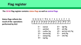
- 1. Flag register The 16 bit flag register contains status flags as well as control flags Status flags reflects the result of the operations performed by ALU
- 2. Bits of the flag register ● CF: This flag is set whenever there is a carry , either from D7 after an 8-bit operation, or from D15 after a 16 bit operation ● PF: This flag indicates the parity of the result's low-byte. If the low-byte has even no. of 1s , PF = 1, otherwise PF =0 ● AF: If there is a carry from bit D3 to D4 of an operation, AF is set to 1 ● ZF: This flag is set to 1, if the result of an arithmetic or logical operation is zero ● SF: After arithmetic and logical operations the sign bit of the result is copied into SF
- 3. Bits of the flag register ● TF: Trap flag - When TF =1, the processor enters the single step execution mode ● IF: Interrupt flag – set/cleared to enable/disable the external maskable interrupts ● DF: Direction flag – to control the direction of string operations; If DF=0 , the string is processed in the autoincrementing mode, otherwise in the autodecrementing mode ● OF: overflow flag – this flag is set whenever the result of a signed operation is too large so that the high-order bit overflows into the sign bit (will discuss in signed number arithmetic) ● All instructions do not affect the flag bits : eg. MOV instructions
- 4. Flag register and ADD instruction ● The flag bits affected by ADD instruction are : CF, PF, AF, ZF, SF and OF
- 5. Flag register and ADD instruction
- 6. Flag register and ADD instruction
- 7. Use of ZF for looping ● Pgm: Add 5 bytes; CX acts as the counter
- 8. 8086 Addressing modes ● Addressing mode indicates how the CPU accesses data or operands ● 8086 provides a total of 7 distinct addressing modes ● Register ● Immediate ● Direct ● Register indirect ● Based relative ● Indexed relative ● Based indexed relative
- 9. Register Addressing mode ● Uses registers to hold the data to be manipulated ● Memory is not accessed when instructions of this addressing mode is executed ; hence relatively fast ● Examples: ● MOV BX, DX ● MOV ES, AX ● ADD AL, BL ● ADC AH, BH
- 10. Immediate Addressing mode ● In the immediate addressing mode, the source operand is a constant ● The data is a part of the instruction ● Examples: ● MOV AX, 2550H ● MOV CX, 625 ● MOV BL, 40H
- 11. Direct Addressing mode ● In the direct addressing mode, the data is in some memory location(s) and the address of the data comes immediately after the opcode ● This address is the offset address ● The physical address will be calculated by combining the DS and the offset ● Examples ● MOV DL, [2400] ● MOV AX,[1520] ● MOV [3510], AX
- 12. Register Indirect Addressing mode ● The address of the memory location where the operand resides is held by a register ● The registers used for this purpose are SI, DI and BX ● They must be combined with DS in order to generate the 20-bit physical address ● Examples ● MOV AL,[BX] ● MOV AX,[BX] ● MOV CL, [SI] ● MOV [DI], AH ● Assume that DS =1120, SI =2498, and AX =17FE. Show the contents of the memory locations after the execution of MOV [SI], AX
- 13. Based relative Addressing mode ● In this addressing mode, the base registers BX/BP and an 8-bit or 16-bit displacement value are used to calculate the offset ● The default segments used for physical address calculation are DS for BX and SS for BP ● Examples ● MOV CX, [BX]+10 ; move contents of DS: BX+10 and DS: BX+10+1 into CX ● Alternative coding MOV CX, [BX+10] or MOV CX, 10[BX] ● MOV AL, [BP]+5 ; move contents of SS: BP+5 into AL
- 14. Indexed relative Addressing mode ● In this addressing mode, the index registers SI/DI and an 8-bit or 16-bit displacement value are used to calculate the offset ● The default segment used for physical address calculation is DS ● Examples ● MOV DX, [SI]+10 ; move contents of DS: SI+10 and DS: SI+10+1 into DX ● Alternative coding MOV DX, [SI+10] or MOV DX, 10[SI] ● MOV AL, [DI]+20
- 15. Based Indexed relative Addressing mode ● In this addressing mode, the base registers BX/BP , index registers SI/DI and 8- bit or 16-bit displacement value are used to calculate the offset ● Examples ● MOV CL, [BX][DI]+8 ; PA = DS(shifted left)+BX+DI+8 ● MOV CH, [BX][SI]+20 ; PA= DS(shifted left)+BX+SI+20 ● MOV AH, [BP][SI]+29 ; PA = SS(shifted left) +BP+SI+29 ● MOV AH, [BP][DI]+12 ; PA = SS(shifted left) +BP+DI+12 ● MOV AX, [SI][DI]+displacement is illegal ● Even though we showed examples with MOV, there are several other instructions which supports the above addressing modes
- 16. Segment Overrides ● The 8086 allows overriding the default segment with other segment registers ● To do that we specify the segment in the code ● Examples ● MOV AL,[BX] ; By default PA = DS(shifted left) + BX ● MOV AL, ES:[BX] ; Overriding the default segment PA = ES(shifted left) + BX
- 18. Summary of Addressing modes
- 20. Programming 8086 ● We are assuming that we are going to assemble and execute the 8086 programs that we write on a PC with an intel microprocessor 8086 or higher ● In a PC, memory management is the task of the operating system and hence the values for the CS, DS and SS registers will be assigned by OS ( As a user we do not have the knowledge about the actual physical memory locations that are free ) ● When the user program begins execution, the OS would have already assigned values to the CS and SS. The DS ( and ES, if used) will be initialized inside the user program.
- 21. Sample Program (adding two bytes) .MODEL SMALL .STACK 64 .DATA DATA1 DB 52H DATA2 DB 29H SUM DB ? .CODE MAIN PROC FAR MOV AX, @DATA MOV DS, AX MOV AL, DATA1 MOV BL, DATA2 ADD AL, BL MOV SUM, AL MOV AH, 4CH INT 21H MAIN ENDP END MAIN
- 22. Components of the sample program ● .MODEL is an assembler directive; it selects one among the different memory models SMALL, MEDIUM, COMPACT, LARGE, HUGE etc. ● The SMALL model uses a maximum of 64 Kbytes for code and another 64 Kbytes for data
- 23. Components of the sample program ● The ALP statements are grouped into different segments ● A typical program uses CODE, DATA and STACK segments ● To mark the beginning of a segment we use an assembler directive ● .CODE marks the beginning of the code segment ● .DATA marks the beginning of the data segment ● .STACK marks the beginning of the stack segment ● .STACK 64 reserves 64 bytes of memory for the stack ● Three data items (DATA1, DATA2, and SUM) are defined in the DATA segment of the program ● The DB directive allocates a byte of memory
- 24. Components of the sample program ● To allocate 2 bytes, we can use DW directive ● We can use the labels for the data items DATA1, DATA2, etc. in the code to refer to their location in the DATA segment ● Procedure is a group of instructions written to accomplish a specific function ● Every procedure must have a name (or label ) defined by the PROC FAR/PROC NEAR directive ● Every procedure must be closed by the ENDP directive ● The PROC and the ENDP statements for a procedure must have the same label ● The entry point to user program must be a FAR procedure (if your code has a single procedure, it should be a FAR procedure)
- 25. Components of the sample program ● The DS value is initialized by the statements MOV AX, @DATA MOV DS, AX ● The instructions below are used to call an OS function to return the control to the operating system ● MOV AH, 4CH ● INT 21H ● The last line ends the entire program; the labels for the entry point and END must match
- 26. A sample skeleton for a program .MODEL SMALL .STACK 64 .DATA ; ;place data definitions here ; .CODE MAIN PROC FAR MOV AX, @DATA MOV DS, AX ; ;place code here ; MOV AH, 4CH INT 21H MAIN ENDP END MAIN
- 27. Program to add 5 bytes (Assume sum <= 255) .MODEL SMALL .STACK 64 .DATA DATA_IN DB 25H, 12H, 15H, 1FH, 2BH SUM DB ? .CODE MAIN PROC FAR MOV AX, @DATA MOV DS, AX MOV CX, 05 MOV BX, OFFSET DATA_IN MOV AL,0 AGAIN: ADD AL,[BX] INC BX DEC CX JNZ AGAIN MOV SUM, AL MOV AH, 4CH INT 21H MAIN ENDP END MAIN
- 28. Program to add 4 16-bit words (assume sum < = 65535) .MODEL SMALL .STACK 64 .DATA DATA_IN DW 234DH, 1DE6H, 3BC7H, 566AH SUM DW ? .CODE MAIN PROC FAR MOV AX, @DATA MOV DS, AX MOV CX, 04 MOV DI, OFFSET DATA_IN MOV BX,0 AGAIN: ADD BX,[DI] INC DI INC DI DEC CX JNZ AGAIN MOV SI, OFFSET SUM MOV [SI], BX MOV AH, 4CH INT 21H MAIN ENDP END MAIN
- 29. Program to copy 6 bytes of data from memory locations with offset 0010H to memory locations with offset 0028H .MODEL SMALL .STACK 64 .DATA ORG 10H DATA_IN DB 25H, 4FH, 85H, 1FH, 2BH, 0C4H ORG 28H COPY DB 6 DUP(?) .CODE MAIN PROC FAR MOV AX, @DATA MOV DS, AX MOV SI, OFFSET DATA_IN MOV DI, OFFSET COPY MOV CX, 06H AGAIN: MOV AL,[SI] MOV [DI],AL INC SI INC DI DEC CX JNZ AGAIN MOV AH, 4CH INT 21H MAIN ENDP END MAIN
- 30. Write a program to calculate the sum of 5 bytes. (result can exceed 255)
- 31. Sum of 5 words of data (result can exceed 65535)
- 32. Sum of two multi-word numbers