
Recommended
Recommended
More Related Content
What's hot
What's hot (19)
Similar to Process equipment numericals problems
Similar to Process equipment numericals problems (20)
Recently uploaded
Recently uploaded (20)
Process equipment numericals problems
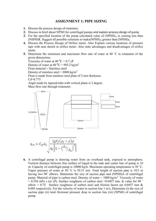
- 1. ASSIGNMENT 1: PIPE SIZING 1. Discuss the process design of rotameter. 2. Discuss in brief about NPSH for centrifugal pumps and explain process design of pump 3. For the specified location of the pump calculated value of (NPSH)A is coming less than (NSPH)R. Suggest all possible solutions to make(NPSH)A greater than (NPSH)R. 4. Discuss the Process Design of Orifice meter. Also Explain various locations of pressure taps with neat sketch in orifice meter. Also state advantages and disadvantages of orifice meter. 5. Determine the minimum and maximum flow rate of water at 40 ˚C in rotameter of the given dimensions. Viscosity of water at 40 ⁰C = 0.7 cP Density of water at 40 ⁰C = 992.2 kg/m3 Float material = Stainless steel Density of stainless steel = 8000 kg/m3 Float is made from stainless steel plate of 2 mm thickness. Cd=0.775 Angle made by tapered tube with vertical plane is 2 degree. Mass flow rate through rotameter: 6. A centrifugal pump is drawing water from an overhead tank, exposed to atmosphere. Vertical distance between free surface of liquid in the tank and center line of pump is 10 m. Capacity of centrifugal pump is 10000 kg/h. Maximum operating temperature is 50 ˚C. Vapor pressure of water at 50 ˚C is 92.51 torr. Total length of suction pipe is 10.5 m having two 90˚ elbows. Determine the size of suction pipe and (NPSH)A of centrifugal pump. Material of pipe is carbon steel. Density of water = 1000 kg/m3 . Viscosity of water = 0.558 mPa s (or cP). Surface roughness of carbon steel =0.0457 mm. K value for 90 ˚ elbow = 0.75. Surface roughness of carbon steel and friction factor are 0.0457 mm & 0.005 respectively. For the velocity of water in suction line 1 m/s, Determine (i) the size of suction pipe (ii) total frictional pressure drop in suction line (iii) (NPSH) of centrifugal pump.
- 2. 7. Hexane at 40 0 C is pumped through the system at the rate of 10 m3/hr. The tank is at atmospheric pressure. Pressure at the end of the discharge pipe is 400 kPa g. The discharge is 4.5 m above the pump center line while the suction lift is 1 m above the level of the liquid in the tank. The friction loss in the suction line is 4 kPa and that in the discharge line is 40 kPa. The mechanical efficiency of the pump is 65%. The density of hexane is 650 kg/m3 and its vapour pressure at 40 0 C is 35 kPa. Calculate power required by centrifugal pump 8. Calculate the Manometer reading generated by orifice meter based on following data: Name of the fluid: Water Flow rate: 90000 kg/h Inside diameter of pipe=154 mm Operating temperature = 32 °C Density of water = 995 kg/m3 Viscosity of water = 0.765 cP Manometer fluid = Mercury, Density of mercury = 13516.47 kg/m3 Take β = 0.5. C0=0.6055 9. A three stage reciprocating compressor is used to compress 306 Sm3 /h of methane from 0.95 atm a to 61.3 atm a. The inlet temperature is 26.7 °C. Specific heat ratio of methane is 1.31. Calculate (1) Power required for compression, if mechanical efficiency is 80% and (2) discharge temperature of gas after 1st stage. 10. Benzene at 38°C is pumped through the system at a rate 9.09 m3/hr with the help of a centrifugal pump. The reservoir is at atmospheric pressure. Pressure at the end of discharge line is 345 kPa g. The discharge head is 3.05 meter and the pump suction head is 1.22 meter above the level of liquid in reservoir. The friction loss in suction line is 3.45 kPa and that in discharge line is 37.9 kPa. The mechanical efficiency of the pump is 0.6. The density of benzene is 865 kg/m3 and its vapor pressure at 38°C is 26.2 kPa. Calculate (1) NPSH and (2) Power required by pump. Power required by pump is given by, Where P= power required in kW, H= Total dynamic head in meter, qv= volumetric flow rate, m3 /hr, ρ= density of fluid, kg/m3 , η= mech. efficiency of pump. 11. Carbon dioxide is to be conveyed from the top of the stripper of ammonia plant to urea plant. Calculate the pipe size required based on following data. (i) Flow rate of CO2 = 1000 t/day (ii) Total length of pipe = 800 m (iii) Available pressure at inlet of pipe = 24 kPa g (iv) Discharge pressure of CO2 from pipe required = atmospheric (v) No. of butterfly valve in pipeline = 1 (vi) No. of 90o elbows in pipeline = 8 (vii) Temperature of gas = 60o C (viii) Viscosity of CO2 gas = 0.016 cP (ix) Equivalent number of velocity heads for butterfly valve =0.24 (x) Equivalent number of velocity heads for 90o elbows = 0.75 (xi)MOC of Pipe = Carbon Steel
- 3. ASSIGNMENT 2 HEAT EXCHANGER 1. In design of vertical thermosyphon reboiler recirculation ratio is determined via trial and error calculations. In these calculations one of the following hypothetical conditions arises for the assumed value of recirculation ratio. (i) Δ Pav ≈ Δ Pt (ii) Δ Pav >> Δ Pt (iii) Δ Pav < Δ Pt Discuss how to find or fix the recirculation ratio in each of the above condition. 2. Discuss process design of Thermosyphon reboiler. 3. Discuss the design procedure for Kettle type Reboiler. 4. Discuss the design of plate type heat exchanger. 5. Describe in brief criteria of selection between horizontal and vertical condenser. 6. Discuss in detail about criteria of selection between kettle type and thermosyphon reboiler. 7. State the functions of the followings in shell and tube heat exchanger. (1) Baffles (2) tie rods (3) spacers (4) Tube sheet (5) sealing strips 8. Baffle spacing in heat exchanger, 9. Discuss the Advantages and disadvantages of plate heat exchanger over shell and tube heat exchanger. 10.Write a brief note on selection of heating media and cooling media in heat Exchanger OR Write a brief note on Fluid allocation in shell and tube heat exchanger. 11.Give the stepwise design procedure for Shell & Tube heat exchanger. 12.Explain in brief Tinker’s Flow Model for Shell and Tube heat exchanger. 13.State the various types of shell and tube heat exchanger. Discuss the advantagesand disadvantages of different types of shell and tube heat exchanger with each other. 14.Gas oil at 200 °C is to be cooled to 40 °C. The oil flow rate is 22500 kg/h. Cooling water is available at 30 °C and the temperature rise is to be limited to 20 °C. The pressure drop allowance for each stream is 100 kN/m2 . Design a suitable heat exchanger. Physical properties of the fluid: Temperature correction factor Ft = 0.94 Base your design on overall heat transfer coefficient = 500 W/m2 °C Tube OD = 20 mm, Tube ID = 16mm, Tube length = 4m, Triangular pitch pt=1.25dO, Number of tube side passes =04, Shell diameter = 667 mm, baffle spacing = 133 mm Take water in tube side. Oil side heat transfer coefficient = 5000 W/m2 °C Water side heat transfer coefficient = 4000 W/m2 °C Thermal conductivity of tube wall material = 45 W/m °C
- 4. Assume the pressure drop are within permissible limit. shell side heat transfer coefficient: 15.10900 kg/h of nearly pure saturated methyl ethyl ketone (MEK) vapor at 13.73 kPa g is to be condensed and cooled to 60 ᵒC by cooling water which is available in plant at 32 ᵒC. Assme Uc = 800 W/m2 ᵒC and Usub = 200 W/m2 ᵒC. Calculate the % excess heat transfer area for the given condenser. (1) Latent heat of condensation of MEK at condensation temperature, 83.87ᵒC = 438.27 KJ/Kg (2) Specific heat of MEK liquid = 2.298 KJ/Kg ᵒC (3) No. of tube side pass = 4 , for 4 passes k1 = 0.175, n1 = 2.285 (4) Tube OD = 19.05 mm , Tube ID = 15.748 mm , Tube length = 1.83 m (5) Viscosity of water = 0.72 cP, (6) Thermal conductivity of water = 0.6228 W/m ᵒC (7) Mean temperature of condensate film = 71.22 ᵒC (8) Physical properties of MEK liquid condensate at 71.22 ᵒC, Viscosity = 0.31 cP, density = 805 kg/m3 , Thermal conductivity = 0173 W/m ᵒC (9) For subcooling zone hosub = 283.77 W/m2 ᵒC (10) dirt factor for organic vapor = 10000 W/m2 ᵒC (11) dirt factor for cooling water = 4000 W/m2 ᵒC (12) Thermal conductivity of SS 304 material = 16.3 W/m ᵒC 16.1-2 shell and tube heat exchanger is used to cool methanol condensate from 95 °C to 40°C. Flow rate of methanol is 100000 kg/h. Brackish water is used as coolant with temperature rise from 25 °C to 40 °C. Property Methanol Brackish Water Heat Capacity, kJ/kg °C 2.84 4.2 Density, kg/m3 750 995 Viscosity, mNs/m2 0.34 0.8 Thermal conductivity, W/m °C 0.19 0.59 Choose 20mm od, 16 mm id, 4.88 m long cupro-nickle tubes with triangular pitch Pt=1.25dO. Based on overall heat transfer coefficient 600 W/m2 °C, Calculate (1) Number of tubes (2) Shell Diameter (3) Tube side heat transfer coefficient. (Take brackish water in tubes). K1 and n1 for tube bundle diameter: (For triangular pitch pt=1.25dO) No of tube side passes 1 2 4 6 8 K1 0.319 0.249 0.175 0.0743 0.0365
- 5. n1 2.142 2.207 2.285 2.499 2.675 Heat transfer coefficient for tube side: for Re>4000 NU =0.023RQ 0.8Pr 0.33(µ/ µW)0.14 17.50000 kg/hr ethanol liquid is to be cooled from 850 C to 500 C in gasketed plate heat exchanger. Operating pressure at the inlet of heat exchanger is 2 atm g. Cooling water is available at 320 C, is used as a cooling medium. Design the suitable plate heat exchanger. Assume the temperature correct ion factor to be 0.97. Select the effective plate width 0.5 m and effective plate length 1.5 m having plate thickness 1 mm. Take gap between successive plate to be 3 mm. Assume the constant to be a=0.65, b= 0.4 and c=0.26. Take density of ethanol = 775 kg/m3 and viscosity to be 0.6 cP Thermal conductivity of ethanol = 0.147 W/ (m. 0 C) and sp. heat = 2.84 KJ /Kg K Take density of water = 1000 kg/m3 and viscosity to be 0.8 cP Thermal conductivity of water = 0.62 W/ (m. 0 C) and sp. heat = 4.186 KJ /Kg K. Assume the fouling coefficient of water and ethanol to be 10000 w/ (m2 . 0 C) Assume plate material to be titanium with thermal conductivity = 21 W/ (m. 0 C) Start the design assuming U = 1500 W/m2 K and finalize after one trial only the area required as per 10% excess area. Pressure drop calculation is not required. 18.Design shell and tube horizontal condensor for condensation of 46000 kg/hr n-propanol at 0.25 kgf/cm2 g by cooling water at 320 C. The condensing temp. at this pressure is 81.2 0 C. The dirt factors of both shell and tube side is 2000 kcal/hr m2 C. Assume that allowable pressure drop on both the side is within limit. Assume the tube o.d. of 19.05 mm and 23.81 mm triangular pitch. Tube wall thickness to be taken as 1.65 mm. Assume isothermal condensation. Properties for n-propanol: Latent heat of condensation: 158 kcal/kg Thermal conductivity : 0.14 kcal/hr m C Liquid density : 800 kg/m3 Liquid viscosity: 0.62 cP Vapor viscosity: 0.01 cP Assume thermal conductivity of tube metal = 39 kcal/hr mC Condensation coefficient is to be calculated as Where,
- 6. Water side coefficient is calculated as: Where, t = water side average temperature, 0 C di = inside diameter of tube, mm ut = tube side velocity, m/sec For triangular pitch, constants for bundle diameter are as: 19.A horizontal 1-4 heat exchanger (condenser) is used to condense 45000 kg/hr of mixed light hydrocarbon vapors. The condenser to operate at 10 bar. The vapor will enter the condenser saturated at 60 °C and the condensation will be completed at 45 °C. The average molecular weight of vapor is 52. The enthalpy of the vapor is 596.5 kJ/kg and the condensate 247 kJ/kg. Cooling water is available at 30 °C and the temperature rise is limited to 10°C. Plant standards requires tubes of 20 mm od, 16.8 mm id, 4.88 m long of admiralty brass. Use square pitch tube arrangement with pt=1.25dO. The vapors are to be totally condensed and no sub cooling is required. Take temperature correction factor Ft=0.92. Based on overall heat transfer coefficient = 900 W/m2°C, Calculate (1) Number of tubes (2) Shell Diameter (3) Tube side heat transfer coefficient and (4) Shell side heat transfer coefficient Physical properties of condensate at 47°C are: μL=0.16 mNs/m, ρL=551 kg/m3, kL=0.13W/m°C. Specific heat of water at 35°C=4.18 kJ/kg C. Density of water = 993 kg/m3, Thermal conductivity of water = 0.628 W/m ° 20.Lube oil is to be cooled from 65 °C to 45 °C by using cooling water in shell and tube heat exchanger having following data. Lube oil flow rate - 450 L/min Density of lube oil - 869 kg/m3 Specific heat of lube oil - 2.1413 kJ/kg °C Thermal conductivity of lube oil - 0.13 W/m °C Viscosity of lube oil - 15 cP Cooling water inlet temperature - 35 °C Cooling water outlet temperature - 39 °C Specific heat of water - 4.1868 kJ/kg°C Viscosity of water - 0.73 cP
- 7. Thermal conductivity of water - 0.628 W/m °C Density of Water - 993.32 kg/m3 Specification of fixed tube sheet heat exchanger: Shell inside diameter – 418 mm Tube O.D. - 15.875 mm Type of baffle – 25 % segmental Tube I.D -13.3858 mm Baffle spacing - 83.6 mm Tube length - 3.048 m Tube pitch - 1.25dO Type of tube arrangement - Triangular Nos. of tube side passes – 4 LMTD correction factor : 0.95 Assume overall heat transfer Coefficient = 400 W/m2 °C Fixed tube sheet type shell and tube heat exchanger is used for this duty. Take lube oil on shell side and water on tube side. Calculate (i) Number of tubes (ii) tube side heat transfer coefficient (iii) shell side heat transfer coefficient. Use following correlation: ASSIGNMENT 3 EXTRACTION 1. State and discuss the industrial applications of liquid-liquid extraction. 2. Discuss the criteria for the choice of solvent for liquid – liquid extraction OR Discuss the desirable solvent properties required in liquid-liquid extraction. 3. Discuss the Process design of Horizontal and Vertical Settlers in details 4. Explain the process design of counter current multistage extractor. 5. State the merits and demerits of mixer-settler. Discuss the design steps for the process design of horizontal and vertical gravity settler. OR Discuss the process design of settlers. 6. For the separation of dimethylformamide (DMF) from its dilute solution having a flow rate of 1000 kg/h and containing 20 % DMF by mass is to be counter currently extracted with methylene chloride to reduce the DMF concentration to 1 % in the final raffinate. Determine (i) the minimum amount of solvent which can be used and (ii) the number of theoretical stages if actual amount of solvent is double than the minimum required. Phase equilibrium equation is given by 𝑌=0.5555 𝑋 at 25 o C where, Yand X are mass fractions of solute.