final report
•Download as DOCX, PDF•
2 likes•1,120 views

This document provides an overview of the development of laser technology. It discusses how Albert Einstein first explained the theory of stimulated emission in 1917, which became the basis for lasers. In the late 1940s and 1950s, scientists like Charles Townes, Alexander Prokhorov, and Nikolai Basov began pioneering work to develop practical devices using this principle, creating the first maser. Theodore Maiman then invented the first working laser in 1960, using a ruby crystal as the lasing medium. Since then, lasers have advanced significantly and found applications in many fields due to their unique properties of being highly directional, coherent beams of light.

Recommended
More Related Content
What's hot
What's hot (20)
Viewers also liked
Similar to final report
Similar to final report (20)
More from Ajeet Kumar
More from Ajeet Kumar (9)
Recently uploaded
Recently uploaded (20)
final report
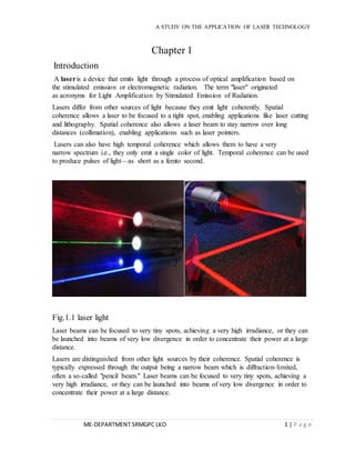
- 1. A STUDY ON THE APPLICATION OF LASER TECHNOLOGY Chapter 1 Introduction A laser is a device that emits light through a process of optical amplification based on the stimulated emission or electromagnetic radiation. The term "laser" originated as acronyms for Light Amplification by Stimulated Emission of Radiation. Lasers differ from other sources of light because they emit light coherently. Spatial coherence allows a laser to be focused to a tight spot, enabling applications like laser cutting and lithography. Spatial coherence also allows a laser beam to stay narrow over long distances (collimation), enabling applications such as laser pointers. Lasers can also have high temporal coherence which allows them to have a very narrow spectrum i.e., they only emit a single color of light. Temporal coherence can be used to produce pulses of light—as short as a femto second. Fig.1.1 laser light Laser beams can be focused to very tiny spots, achieving a very high irradiance, or they can be launched into beams of very low divergence in order to concentrate their power at a large distance. Lasers are distinguished from other light sources by their coherence. Spatial coherence is typically expressed through the output being a narrow beam which is diffraction- limited, often a so-called "pencil beam." Laser beams can be focused to very tiny spots, achieving a very high irradiance, or they can be launched into beams of very low divergence in order to concentrate their power at a large distance. ME-DEPARTMENT SRMGPC LKO 1 | P a g e
- 2. A STUDY ON THE APPLICATION OF LASER TECHNOLOGY Properties of laser 1. The light emitted by lasers is different from that produced by more common light sources such as incandescent bulbs, fluorescent lamps, and high-intensity arc lamps. An understanding of the unique properties of laser light may be achieved by contrasting it with the light produced by other, less unique sources. 2. Highly directional nature of light produced by a laser. "Directionality" is the characteristic of laser light that causes it to travel in a single direction within a narrow cone of divergence. 3. It consists of an extremely narrow range of wavelengths within the red portion of the spectrum. It is said to nearly monochromatic, meaning that it consists of light of almost single wavelength. 4. Coherence is the most fundamental property of laser light and distinguishes it from the light from other sources. Thus, a laser may be defined as a source of coherent light. So that laser light is highly coherent, means that phases at every instant of time are always same. ME-DEPARTMENT SRMGPC LKO 2 | P a g e Fig. 1.2 First, let's discuss the properties of laser light and then we will go into how is created. Laser light is monochromatic, directional, and coherent. Fig.1.3
- 3. A STUDY ON THE APPLICATION OF LASER TECHNOLOGY Chapter 2 History of laser Max Plank published work in 1900 that provided the understanding that light is a form of electromagnetic radiation. Without this understanding the laser would not have been invented. The principle of the laser was first known in 1917, when physicist Albert Einstein described the theory of stimulated emission. However, it was not until the late 1940s that engineers began to utilize this principle for practical purposes. At the onset of the 1950’s several different engineers were working towards the harnessing of energy using the principal of stimulated emission. At the University of Columbia was Charles Townes, at the Univers ity of Maryland was Joseph Weber and at the Lebedev Laboratories in Moscow were Alexander Prokhorov and Nikolai G Basov. At this stage the engineers were working towards the creation of what was termed a MASER (Microwave Amplification by the Stimulated Emission of Radiation), A device that amplified microwaves as opposed to light and soon found use in microwave communication systems. Townes and the other engineers believed it to be possible to create an optical maser, A device for creating powerful beams of light using higher frequency energy to stimulate what was to become termed the lasing medium. Despite the pioneering work of Townes and Prokhorov it was left to Theodore Maiman in 1960 to invent the first Laser using a lasing medium of ruby that was stimulated using high energy flashes of intense light. Townes and Prokhorov were later awarded the Nobel Science Prize in 1964 for their endeavors. Fig 2.1 scientist who developed laser The Laser was a remarkable technical breakthrough, but in its early years it was something of a technology without a purpose. It was not powerful enough for use in the beam weapons envisioned by the military, and its usefulness for transmitting information through the atmosphere was severely hampered by its inability to penetrate clouds and rain. Almost immediately, though, some began to find uses for it. Maiman and other engineers developed laser weapons sighting systems and powerful lasers for use in surgery and other. ME-DEPARTMENT SRMGPC LKO 3 | P a g e
- 4. A STUDY ON THE APPLICATION OF LASER TECHNOLOGY Albert Einstein first explained the theory of stimulated emission in 1917, which became the basis of Laser. He postulated that, when the population inversion exists between upper and lower levels among atomic systems, it is possible to realize amplified stimulated emission and the stimulated emission has the same frequency and phase as the incident radiation. However, it was in late 1940s and fifties that scientists and engineers did extensive work to realize a practical device based on the principle of stimulated emission. Notable scientists who pioneered the work include Charles Townes, Joseph Weber, Alexander Prokhorov and Nikolai G Basov. Initially, the scientists and engineers were working towards the realization of a MASER (Microwave Amplification by the Stimulated Emission of Radiation) ; a device that amplified microwaves for its immediate application in microwave communication systems. Townes and the other engineers believed it to be possible create an optical maser, a device for creating powerful beams of light using higher frequency energy to stimulate what was to become termed the lasing medium. Despite the pioneering work of Townes and Prokhorov it was left to Theodore Maiman in 1960 to invent the first Laser using ruby as a lasing medium that was stimulated using high energy flashes of intense light. The development of Lasers has been a turning point in the history of science and engineering. It has produced a completely new type of systems with potentials for applications in a wide variety of fields. During sixties, lot of work had been carried out on the basic development of almost all the major lasers including high power gas dynamic and chemical lasers. Almost all the practical applications of these lasers in defense as well as in industry were also identified during this period. The motivation of using the high power lasers in strategic scenario was a great driving force for the rapid development of these high power lasers. In early seventies, megawatt class carbon dioxide gas dynamic laser was successfully developed and tested against typical military targets. The development of chemical lasers, free electron and X-ray lasers took slightly longer time because of involvement of multidisciplinary approach. The major steps of advances or breakthroughs in Laser research are given below: Dates, Contributors and events: 1917: Einstein, A. - Concept and theory of stimulated light emission 1948: Gabor, D. - Invention of holography 1951: Charles H Townes, Alexander Prokhorov, Nikolai G Basov, Joseph Weber - The invention of the MASER (Microwave Amplification of Stimulated Emission of Radiation) at Columbia University, Lebedev Laboratories, Moscow and University of Maryland. 1956: Bloembergen, N. - Solid-state maser- [Proposal for a new type of solid state maser] at Harvard University. 1958: Schawlow, A.L. and Townes, C.H. - Proposed the realization of masers for light and infrared at Columbia University. ME-DEPARTMENT SRMGPC LKO 4 | P a g e
- 5. A STUDY ON THE APPLICATION OF LASER TECHNOLOGY 1960: Maiman, T.H. - Realization of first working LASER based on Ruby at Hughes Research Laboratories. 1961: Javan, A., Bennet, W.R. and Herriot, D.R. - First gas laser: Helium- Neon (He-Ne laser) at Bell Laboratories. 1961: Fox, A.G., Li, T. - Theory of optical resonators at Bell Laboratories. 1962: Hall,R. - First Semiconductor laser (Gallium-Arsenide laser) at General Electric Labs. 1962: McClung,F.J and Hellwarth, R.W. - Giant pulse generation / Q-Switching. 1962: Johnson, L.F., Boyd, G.D., Nassau, K and Sodden, R.R. - Continuous wave solid-state laser. 1964: Geusic, J.E., Markos, H.M., Van Uiteit, L.G. - Development of first working Nd:YAG LASER at Bell Labs. 1964: Patel, C.K.N. - Development of CO2 LASER at Bell Labs. 1964: Bridges, W. - Development of Argon Ion LASER a Hughes Labs. 1965: Pimentel, G. and Kasper, J. V. V. - First chemical LASER at University of California, Berkley. 1965: Bloembergen, N. - Wave propagation in nonlinear media. 1966: Silfvast, W., Fowles, G. and Hopkins - First metal vapor LASER - Zn/Cd - at University of Utah. 1966: Walter, W.T., Solomon, N., Piltch, M and Gould, G. - Metal vapor laser. 1966: Sorokin, P. and Lankard, J. - Demonstration of first Dye Laser action at IBM Labs. 1966: AVCO Research Laboratory, USA. - First Gas Dynamic Laser based on CO2 1970: Nikolai Basov's Group - First Excimer LASER at Lebedev Labs, Moscow based on Xenon (Xe) only. 1974: Ewing, J.J. and Brau, C. - First rare gas halide excimer at Avco Everet Labs. 1977: John M J Madey's Group - First free electron laser at Stanford University. 1977: McDermott, W.E., Pehelkin, N.R,. Benard, D.J and Bousek, R.R. - Chemical Oxygen Iodine Laser (COIL). 1980: Geoffrey Pert's Group - First report of X-ray lasing action, Hull University, UK. 1984: Dennis Matthew's Group - First reported demonstration of a "laboratory" X-ray laser from Lawrence Livermore Labs. 1999: Herbelin,J.M., Henshaw, T.L., Rafferty, B.D., Anderson, B.T., Tate, R.F., Madden, T.J., Mankey II, G.C and Hager, G.D. - All Gas-Phase Chemical Iodine Laser (AGIL). 2001: Lawrence Livermore National Laboratory - Solid State Heat Capacity Laser (SSHCL). ME-DEPARTMENT SRMGPC LKO 5 | P a g e
- 6. A STUDY ON THE APPLICATION OF LASER TECHNOLOGY Development of lasernd Stimulated Light 1. In 1905 German scientist Albert Einstein announced his own theory about light, namely that it is made up of both particles and waves. Einstein claimed that the particles, called photons (from the Greek word for "light"), move along in wavelike patterns. Later, other scientists performed experiments that proved Einstein was right. Einstein himself then went on to predict some more startling things about light, first and foremost how photons are made. He agreed with some other scientists of his day about how light sources (like candles, light bulbs, or the sun) produce photons. The researchers thought that atoms (the tiny particles that make up all material in the universe) give off photons. Some form of energy—such as heat, electricity, or chemical energy—might "excite" an atom, or make it more energetic. It would then emit (give off) a photon. Afterward, the atom would go back to its normal, unexcited state. Because there are huge numbers of atoms, they give off equally large numbers of photons. A 100-watt light bulb gives off about 10 trillion photons every second. 2. 1951, while sitting on a park bench, Townes had a brilliant idea. He realized it might be possible to use molecules of ammonia to produce a powerful microwave beam. (A molecule consists of two or more atoms that are connected together.) Townes reasoned Charles Townes (left) and James P. Gordon proudly display their maser, a device that greatly amplifies microwaves. That when molecules of ammonia became excited (by heat, electricity, or chemical energy), they could be stimulated to emit microwaves of the type he was working with. He knew this process would be almost identical to the one Einstein described for stimulating visible light. The only difference was that Townes would be using microwaves instead of light. He calculated that if the ammonia molecules could be kept in an excited state long enough, they might be stimulated to produce more and more microwaves. Eventually, the waves would become concentrated and more powerful. In short, the microwaves would be amplified.Townes decided to try to build a working model. He enlisted the aid of two other researchers, Herbert J. Zigler and James P. Gordon. Working diligently, by 1954 the three men had a working device that operated in the following way: First, some ammonia gas was heated until many of the molecules became excited and then were separated from the unexcited molecules. Next, the excited ME-DEPARTMENT SRMGPC LKO 6 | P a g e
- 7. A STUDY ON THE APPLICATION OF LASER TECHNOLOGY molecules flowed into a chamber called the resonant cavity (or resonator) where the stimulation of the molecules took place. As the excited ammonia molecules began to emit microwave particles, the particles began to bounce back and forth inside the chamber. When one of these particles came near an excited molecule, the molecule suddenly gave off its own particle. Thus the particles themselves stimulated the production of more particles. Soon the number of particles doubled, and then doubled again and again until the microwaves in the chamber had become very powerful. 3. By 1960 many scientists, including Townes and Schawlow, Basov and Prokhorov, and Gould, had asked for laser patents. In addition, the paper published by Townes and Schawlow had caused widespread interest in lasers in the American scientific community. Researchers in labs around the country raced to be first to construct a working model. The first successful device appeared on July 7, 1960, built by a previously unknown researcher who had worked totally on his own—Theodore H. Maiman of the Hughes Aircraft Company in Malibu, California. Maiman's laser was small (only a few inches long) and not very complicated. The core of the device consisted of an artificial ruby about one and a half inches long, so Maiman called his invention the "ruby laser." 4. The first gas laser (helium neon) was invented by Ali Javan, in 1960. The gas laser was the first continuous-light laser and the first to operate "on the principle of converting electrical energy to a laser light output." It has been used in many practical applications. 5. In 1962, Robert Hall, created a revolutionary type of laser that is still used in many of the electronic appliances and communications systems that we use every day. Fig. 2.2 laser research center ME-DEPARTMENT SRMGPC LKO 7 | P a g e
- 8. A STUDY ON THE APPLICATION OF LASER TECHNOLOGY Chapter 3 Components of laser All Lasers are comprised of these essential medium Every laser have a three basic components are; 1 Active medium. 2 External source. 3 Optical resonator. Fig.3.1 components of laser 1. The active medium is excited by the external energy source (pump source) to produce population inversion. In the gain medium that spontaneous and stimulated emission of photons takes place, leading to the phenomenon of optical gain, or amplification. Semiconductors, organic dyes, gases (He, Ne, CO2, etc.), solid materials ( YAG, sapphire(ruby) etc.) are usually used as lasing materials and often LASERs are named for the ingredients used as medium. 2. The excitation source, pump source provides energy which is needed for the population inversion and stimulated emission to the system. Pumping can be done in two ways – electrical discharge method and optical method. Examples of pump sources are ME-DEPARTMENT SRMGPC LKO 8 | P a g e
- 9. A STUDY ON THE APPLICATION OF LASER TECHNOLOGY electrical discharges, flash lamps, arc lamps, light from another laser, chemical reactions etc. 3. Resonator guide basically provides the guidance about the simulated emission process. It is induced by high speed photons. Finally, a laser beam will be generated. In most of the systems, it consists of two mirrors. One mirror is fully reflective and other is partially reflective. Both the mirrors are set up on optic axis, parallel to each other. The active medium is used in the optical cavity between the both mirrors. This arrangement only filters those photons which came along the axis and others are reflected by the mirrors back into the medium, where it may be amplified by stimulated emission. Electrons in the atoms of the lasing material normally reside in a steady-state lower energy level. When light energy from the flash lamp is added to the atoms of the lasing material, the majority of the electrons are excited to a higher energy level -- a phenomenon known as population inversion. This is an unstable condition for these electrons. They will stay in this state for a short time and then decay back to their original energy state. This decay occurs in two ways: spontaneous decay -- the electrons simply fall to their ground state while emitting randomly directed photons; and stimulated decay -- the photons from spontaneous decaying electrons strike other excited electrons which causes them to fall to their ground state. This stimulated transition will release energy in the form of photons of light that travel in phase at the same wavelength and in the same direction as the incident photon. If the direction is parallel to the optical axis, the emitted photons travel back and forth in the optical cavity through the lasing material between the totally reflecting mirror and the partially reflecting mirror. The light energy is amplified in this manner until sufficient energy is built up for a burst of laser light to be transmitted through the partially reflecting mirror. As shown in figure 4, a lasing medium must have at least one excited (metastable) state where electrons can be trapped long enough (microseconds to milliseconds) for a population inversion to occur. Although laser action is possible with only two energy levels, most lasers have four or more levels. ME-DEPARTMENT SRMGPC LKO 9 | P a g e
- 10. A STUDY ON THE APPLICATION OF LASER TECHNOLOGY Fig. 3.2 Three level laser energy diagram A Q-switch in the optical path is a method of providing laser pulses of extremely short time duration. A rotating prism like the total reflector in figure 3 was an early method of providing Q-switching. Only at the point of rotation when there is a clear optical path will light energy be allowed to pass. A normally opaque electro-optical device (e.g., a pockets cell) is now often used for a Q-switching device. At the time of voltage application, the device becomes transparent; the light built up in the cavity by excited atoms can then reach the mirror so that the cavity Quality, Q, increases to a high level and emits a high peak power laser pulse of a few nanoseconds duration. When the phases of different frequency modes of a laser are synchronized (locked together), these modes will interfere with each other and generate a beat effect. The result is a laser output with regularly spaced pulsations called "mode locking". Mode locked lasers usually produce trains of pulses with a duration of a few picoseconds to nanoseconds resulting in higher peak powers than the same laser operating in the Q-switched mode. Pulsed lasers are often designed to produce repetitive pulses. The pulse repetition frequency, PRF, as well as pulse width is extremely important in evaluating biological effects. ME-DEPARTMENT SRMGPC LKO 10 | P a g e
- 11. A STUDY ON THE APPLICATION OF LASER TECHNOLOGY Chapter 4 Types of laser 1. Semiconductor laser The laser diode is a light emitting diode with an optical cavity to amplify the light emitted from the energy band gap that exists in semiconductors as shown in figure 11. They can be tuned by varying the applied current, temperature or magnetic field. Fig.4.1 Semiconductor laser diagram 2. Gas laser Gas lasers consist of a gas filled tube placed in the laser cavity as shown in figure 12. A voltage (the external pump source) is applied to the tube to excite the atoms in the gas to a population inversion. The light emitted from this type of laser is normally continuous wave (CW). One should note that if Brewster angle windows are attached to the gas discharge tube, some laser radiation may be reflected out the side of the laser cavity. Large gas lasers known as gas dynamic lasers use a combustion chamber and supersonic nozzle for population inversion. Fig.4.2 Gas laser diagram ME-DEPARTMENT SRMGPC LKO 11 | P a g e
- 12. A STUDY ON THE APPLICATION OF LASER TECHNOLOGY 3. Dye laser Figure 13 shows a dye laser diagram. Dye lasers employ an active material in a liquid suspension. The dye cell contains the lasing medium. Many dyes or liquid suspensions are toxic. Fig.4.3 Common Dye Laser Diagram 4. Free electron laser Free electron lasers such as in figure 14 have the ability to generate wavelengths from the microwave to the X-ray region. They operate by having an electron beam in an optical cavity pass through a wiggler magnetic field. The change in direction exerted by the magnetic field on the electrons causes them to emit photons. ME-DEPARTMENT SRMGPC LKO 12 | P a g e
- 13. A STUDY ON THE APPLICATION OF LASER TECHNOLOGY Fig.4.4 Free Electron Laser Diagram 5. Transverse electromagnetic laser Laser beam geometries display transverse electromagnetic (TEM) wave patterns across the beam similar to microwaves in a wave guide. Figure 9 shows some common TEM modes in a cross section of a laser beam. Fig.4.5 Common TEM laser beam modes A laser operating in the mode could be considered as two lasers operating side by side. The ideal mode for most laser applications is the mode and this mode is normally assumed to easily perform laser hazards analysis. Light from a conventional light source is extremely broadband (containing wavelengths across the electromagnetic spectrum). If one were to place a filter that would allow only a very narrow band of wavelengths in front of a white or broadband light source, only a single light color would be seen exiting the filter. Light from the laser is similar to the light seen from the filter. However, instead of a narrow band of wavelengths none of which is dominant as in the case of the filter, there is a much narrower line width about a dominant center frequency emitted from the laser. The color or wavelength of light being emitted depends on the type of lasing material being used. For example, if a Neodymium: Yttrium Aluminum Garnet (Nd:YAG) crystal is used as the lasing material, light with a wavelength of 1064 nm will be emitted. Table 1 illustrates various types of material currently used for lasing and the wavelengths that are emitted by that type of laser. Note that certain materials and gases are capable of emitting more than one wavelength. The wavelength of the light emitted in this case is dependent on the optical configuration of the laser. ME-DEPARTMENT SRMGPC LKO 13 | P a g e
- 14. A STUDY ON THE APPLICATION OF LASER TECHNOLOGY Table 1 Common Lasers and Their Wavelengths LASER TYPE WAVELENGTH (Nanometers) Argon Fluoride 193 Xenon Chloride 308 and 459 Xenon Fluoride 353 and 459 Helium Cadmium 325 - 442 Rhodamine 6G 450 - 650 Copper Vapor 511 and 578 Argon 457 - 528 (514.5 and 488 most used) Frequency doubled Nd:YAG 532 Helium Neon 543, 594, 612, and 632.8 Krypton 337.5 - 799.3 (647.1 - 676.4 most used) Ruby 694.3 Laser Diodes 630 - 950 Ti:Sapphire 690 - 960 Alexandrite 720 - 780 Nd:YAG 1064 Hydrogen Fluoride 2600 - 3000 Erbium:Glass 1540 Carbon Monoxide 5000 - 6000 Carbon Dioxide 10600 Light from a conventional light source diverges or spreads rapidly show in fig 16. The intensity may be large at the source, but it decreases rapidly as an observer moves away from the source. ME-DEPARTMENT SRMGPC LKO 14 | P a g e
- 15. A STUDY ON THE APPLICATION OF LASER TECHNOLOGY Figure 4.6 Divergence of Conventional Light Source In contrast, the output of a laser as shown in figure 17 has a very small divergence and can maintain high beam intensities over long ranges. Thus, relatively low power lasers are able to project more energy at a single wavelength within a narrow beam than can be obtained from much more powerful conventional light sources. Fig.4.7 Divergence of Laser Source For example, a laser capable of delivering a 100 mJ pulse in 20 ns has a peak power of 5 million watts. A CW laser will usually have the light energy expressed in watts, and a pulsed laser will usually have its output expressed in joules. Since energy cannot be created or destroyed, the amount of energy available in a vacuum at the output of the laser will be the same amount of energy contained within the beam at some point downrange (with some loss in the atmosphere). ME-DEPARTMENT SRMGPC LKO 15 | P a g e
- 16. A STUDY ON THE APPLICATION OF LASER TECHNOLOGY Fig. illustrates a typical laser beam. The amount of energy available within the sampling area will be considerably less than the amount of energy available within the beam. For example, a 100 mW laser output might have 40 mW measured within 1 sample area. The irradiance in this example is 40 mW/ . Fig.4.8 Illustration of Irradiance ME-DEPARTMENT SRMGPC LKO 16 | P a g e
- 17. A STUDY ON THE APPLICATION OF LASER TECHNOLOGY Chapter 5 Working of laser The electromagnetic spectrum consists of the complete range of frequencies from radio waves to gamma rays. All electromagnetic radiation consists of photons which are individual quantum packets of energy. For example, a household light bulb emits about 1,000,000,000,000,000,000,000 photons of light per second! In this course we will only concern ourselves with the portion of the electromagnetic spectrum where lasers operate - infrared, visible, and ultraviolet radiation. Name Wavelength Ultraviolet 100 nm - 400 nm Visible 400 nm - 750 nm Near Infrared 750 nm - 3000 nm Far Infrared 3000 nm - 1 mm Einstein was awarded the Nobel Prize for his discovery and interpretation of the formula - E=mc2 - right? Wrong. Fig 5.1Albert Einstein He won the Nobel Prize for his explanation of the phenomena referred to as the photoelectric effect. When light (electromagnetic energy) is shined on a metal surface in a vacuum, it may ME-DEPARTMENT SRMGPC LKO 17 | P a g e
- 18. A STUDY ON THE APPLICATION OF LASER TECHNOLOGY free electrons from that surface. Fig.5.2 These electrons can be detected as a current flowing in the vacuum to an electrode. The light was not always strong enough to cause this effect, however. When the scientists made the light brighter, no increase in electrons was seen. Only when they changed the color of the light (the wavelength) did they see a change in photoemission of electrons. This was explained by Einstein using a theory that light consists of photons, each with discrete quantum of energy proportional to their wavelength. For an electron to be freed from the metal surface it would need a photon with enough energy to overcome the energy that bound it to the atom. So, making the light brighter would supply more photons, but none would have the energy to free the electron. Light with a shorter wavelength consisted of higher energy photons that could supply the needed energy to free the electron. Now, you ask, "What the heck does this idea of quantum energy have to do with a laser?” Well, with this background under our belts we will continue. ME-DEPARTMENT SRMGPC LKO 18 | P a g e
- 19. A STUDY ON THE APPLICATION OF LASER TECHNOLOGY Chapter 6 Spectroscope of laser light Line width: In fact emission and absorption depend on photon frequency and are characterized by a line width Line broadening types include: 1. Natural, from finite lifetime (H) 2. Phonon, from lattice vibrations (H) 3. Collisional, in gases (H) 4. Strain, from static lattice in homogeneities (I) 5. Impurity ions in host crystal (I) 6. Doppler, in gases (I) Line width Effects A laser beam of intensity I (W/m2), propagating in the direction through a medium with gain coefficient g (m-1) grows in intensity as I = I0 exp(gz) Since g depends on wavelength, this process will increase the intensity for wavelengths near line-center faster than for those in the wings, leading to gain-narrowing of the spectrum. Line width properties Atoms in either upper or lower levels of the laser medium will not interact with a perfectly monochromatic beam. This is the fact that all spectral lines have a finite wavelength or frequency spread, i.e., (fluorescent or spectral line width). This can be seen in both emission and absorption, And if we measured the emission of a typical spectral source as a function of frequency, we will get bell-shaped curve illustrated. The precise shape of the curve is given by the line shape function g(ν), which represents the frequency distribution of the radiation in a given spectral line. The precise form of g(ν) which is normalized so that the area under the curve is unity depends on the particular mechanism causing the spectral broadening. ME-DEPARTMENT SRMGPC LKO 19 | P a g e
- 20. A STUDY ON THE APPLICATION OF LASER TECHNOLOGY Chapter 7 Applications of laser The light beam produced by most lasers is pencil-sized, and maintains its size and direction over very large distances; this sharply focused beam of coherent light is suitable for a wide variety of applications. Lasers have been used in industry for cutting and boring metals and other materials as well as welding and soldering, and for inspecting optical equipment. In medicine, they have been used in surgical operations. CDs and DVDs read and written to using lasers, and lasers also are employed in laser printers and bar-code scanners. They are used in communications, both in fiber optics and in some space and open-air communications; in a manner similar to radio transmission, the transmitted light beam is modulated with a signal and is received and demodulated some distance away. The field of holography is based on the fact that actual wave-front patterns, captured in a photographic image of an object illuminated with laser light, can be reconstructed to produce a three-dimensional image of the object. Lasers have been used in a number of areas of scientific research, and have opened a new field of scientific research, nonlinear optics, which is concerned with the study of such phenomena as the frequency doubling of coherent light by certain crystals. One important result of laser research is the development of lasers that can be tuned to emit light over a range of frequencies, instead of producing light of only a single frequency. Lasers also have been developed experimentally as weaponry. Sophisticated laser system concepts are increasingly being used to address high bandwidth free space optical (FSO) communications needs and for sensing applications. . Terrestrial and space based multi-mega/gigabit FSO links have been demonstrated but still require advances in beam steering, detection schemes, adaptive optics and other methods of mitigating atmospheric effects, and modulated laser encoding before wide applications are to be realized. Optical sensors based on lasers are also progressing both in remote applications as well as in on chip sensing, in communities ranging from environmental sensing to medical diagnostics. Laser based sensing and free space communications both employ sophisticated detection schemes. This meeting reports on the multiple applications of lasers in FSO communications as well as in advanced sensing applications. ME-DEPARTMENT SRMGPC LKO 20 | P a g e
- 21. A STUDY ON THE APPLICATION OF LASER TECHNOLOGY LASER BEAM MACHINING Fig.7.1 Laser beam machining (LBM) is an unconventional machining process in which a beam of highly coherent light called a laser is directed towards the work piece for machining. Since the rays of a laser beam are monochromatic and parallel it can be focused to a very small diameter and can produce energy as high as 100 MW of energy for a square millimeter of area. It is especially suited to making accurately placed holes. It can be used to perform precision micro-machining on all microelectronic substrates such as ceramic, silicon, diamond, and graphite. Examples of microelectronic micro-machining include cutting, scribing & drilling all substrates, trimming any hybrid resistors, patterning displays of glass ME-DEPARTMENT SRMGPC LKO 21 | P a g e
- 22. A STUDY ON THE APPLICATION OF LASER TECHNOLOGY or plastic and trace cutting on semiconductor wafers and chips. A pulsed ruby laser is normally used for developing a high power. Fig.7.2 Extremely short pulses provide for minimal thermal damage to surroundings ME-DEPARTMENT SRMGPC LKO 22 | P a g e
- 23. A STUDY ON THE APPLICATION OF LASER TECHNOLOGY Characteristics of Femtosecond Laser Micromachining 1. Very high peak powers in the range 1013W/cm2 provide for minimal thermal damage to surroundings 2. Very clean cuts with high aspect ratios 3. Sub-micron feature resolution 4. Minimum redeposition 5. Possible to machine transparent materials like glass, sapphire etc. ADVANTAGES: 1. Non-contact machining 2. Very high resolution, repeatability and aspect ratios 3. Localized heating, minimal redeposition 4. No pre/post processing of material 5. Wide range of materials: fragile, ultra-thin and highly reflective surfaces 6. Process can be fully automated. Fig.7.3 INTENSITY DISTRIBUTION: Fig.7.4 Focal length of 9mm FOCAL LENGTH OF 40mm Focal ME-DEPARTMENT SRMGPC LKO 23 | P a g e
- 24. A STUDY ON THE APPLICATION OF LASER TECHNOLOGY Fig 7.5 APPLICATIONS IN MANUFACTURING 1. CLEANING Emerging process, particularly driven by art and monument restoration (I.e. National Museums and Galleries on Merseyside (NMGM) conservation centre Metal surfaces are well-suited for many laser cleaning applications. Optimized beam settings will not metallurgically change or damage the laser treated surface. Only the coating, residue or oxide targeted for removal is affected as the laser beam is precisely adjusted not to react with the underlying metal surface. Laser beam power density is accurately and easily adjusted to achieve cleaning results impossible with all other options. ME-DEPARTMENT SRMGPC LKO 24 | P a g e
- 25. A STUDY ON THE APPLICATION OF LASER TECHNOLOGY Fig .7.6 2.ENGRAVING : Better “engraving” performance on metals Internal glass marking Laser engraving, and laser marking, is the practice of using lasers to engrave or mark an object. The technique does not involve the use of inks, nor does it involve tool bits which contact the engraving surface and wear out. These properties distinguish laser engraving from alternative engraving or marking technologies where inks or bit heads have to be replaced regularly Fig.7.7 2. DRILLING: A high power pulsed Nd:YAG laser is normally used, occasionally a fiber laser is chosen, or a CO2 laser can be used with non-metallic parts. Processing is accomplished through either percussion drilling or trepanning. In the laser drilling ME-DEPARTMENT SRMGPC LKO 25 | P a g e
- 26. A STUDY ON THE APPLICATION OF LASER TECHNOLOGY process, high power density is accomplished by using a high power laser and a focused spot size of 0.05 mm (0.002") to 0.75 mm (0.030"). Fig.7.8 3. WELDING : Solid-state lasers operate at wavelengths on the order of 1 micrometer, much shorter than gas lasers, and as a result require that operators wear special eyewear or use special screens to prevent retina damage. Nd:YAG lasers can operate in both pulsed and continuous mode, but the other types are limited to pulsed mode. The original and still popular solid-state design is a single crystal shaped as a rod approximately 20 mm in diameter and 200 mm long, and the ends are ground flat. Fig.7.9 4. CUTTING: The parallel rays of coherent light from the laser source often fall in the range between 0.06–0.08 inch (1.5–2.0 mm) in diameter. This beam is normally focused and intensified by a lens or a mirror to a very small spot of about 0.001 inches (0.025 mm) to create a very ME-DEPARTMENT SRMGPC LKO 26 | P a g e
- 27. A STUDY ON THE APPLICATION OF LASER TECHNOLOGY intense laser beam. In order to achieve the smoothest possible finish during contour cutting, the direction of beam polarization must be rotated as it goes around the periphery of a contoured workpiece. For sheet metal cutting, the focal length is usually 1.5–3 inches (38–76 mm) Fig7.10 Good edge quality (square ,clean and no burrs) OTHER POPULAR LASER APPLICATIONS ARE 1. Spectroscopy Most types of laser are an inherently pure source of light; they emit near-monochromatic light with a very well defined range of wavelengths. By careful design of the laser components, the purity of the laser light (measured as the "linewidth") can be improved more than the purity of any other light source. This makes the laser a very useful source for spectroscopy. The high intensity of light that can be achieved in a small, well collimated beam can also be used to induce a nonlinear optical effect in a sample, which makes techniques such as Raman spectroscopy possible. Other spectroscopic techniques based on lasers can be used to make extremely sensitive detectors of various molecules, able to measure molecular concentrations in the parts-per-1012 (ppt) level. Due to the high power ME-DEPARTMENT SRMGPC LKO 27 | P a g e
- 28. A STUDY ON THE APPLICATION OF LASER TECHNOLOGY densities achievable by lasers, beam-induced atomic emission is possible: this technique is termed Laser induced breakdown spectroscopy (LIBS). Fig.7.11 2. Heat Treatment Heat treating with lasers allows selective surface hardening against wear with little or no distortion of the component. Because this eliminates much part reworking that is currently done, the laser system's capital cost is recovered in a short time. An inert, absorbent coating for laser heat treatment has also been developed that eliminates the fumes generated by conventional paint coatings during the heat-treating process with CO2 laser beams. One consideration crucial to the success of a heat treatment operation is control of the laser beam irradiance on the part surface. The optimal irradiance distribution is driven by the thermodynamics of the laser-material interaction and by the part geometry. Typically, irradiances between 500-5000 W/cm^2 satisfy the thermodynamic constraints and allow the rapid surface heating and minimal total heat input required. For general heat treatment, a uniform square or rectangular beam is one of the best options. For some special applications or applications where the heat treatment is done on an edge or corner of the part, it may be better to have the irradiance decrease near the edge to prevent melting. Fig.7.12 ME-DEPARTMENT SRMGPC LKO 28 | P a g e
- 29. A STUDY ON THE APPLICATION OF LASER TECHNOLOGY Lunar laser ranging When the Apollo astronauts visited the moon, they planted retro reflector arrays to make possible the Lunar Laser Ranging Experiment. Laser beams are focused through large telescopes on Earth aimed toward the arrays, and the time taken for the beam to be reflected back to Earth measured to determine the distance between the Earth and Moon with high accuracy. Photochemistry Some laser systems, through the process of mode locking, can produce extremely brief pulses of light - as short as picoseconds or femto seconds (10−12 - 10−15 seconds). Such pulses can be used to initiate and analyses chemical reactions, a technique known as photo chemistry. The short pulses can be used to probe the process of the reaction at a very high temporal resolution, allowing the detection of short-lived intermediate molecules. This method is particularly useful in biochemistry, where it is used to analyses details of protein folding and function. Fig7.13 ME-DEPARTMENT SRMGPC LKO 29 | P a g e
- 30. A STUDY ON THE APPLICATION OF LASER TECHNOLOGY Laser Barcode Scanners Laser barcode scanners are ideal for applications that require high speed reading of linear codes or stacked symbols. From small products for embedded OEM applications to rugged laser barcode scanners for industrial use, Micro scan offers a wide range of quality products to read linear barcodes and stacked symbols, with features such as high speed reading, wide field of view, symbol reconstruction, and aggressive decoding technology. Fig7.14 Laser cooling A technique that has recent success is laser cooling. This involves atom trapping, a method where a number of atoms are confined in a specially shaped arrangement of electric and magnetic fields. Shining particular wavelengths of laser light at the ions or atoms slows them down, thus cooling them. As this process is continued, they all are slowed and have the same energy level, forming an unusual arrangement of matter known as a Bose- Einstein condensate. Fig .7.15 ME-DEPARTMENT SRMGPC LKO 30 | P a g e
- 31. A STUDY ON THE APPLICATION OF LASER TECHNOLOGY Nuclear fusion Some of the world's most powerful and complex arrangements of multiple lasers and optical amplifiers are used to produce extremely high intensity pulses of light of extremely short duration. These pulses are arranged such that they impact pellets of tritium-deuterium simultaneously from all directions, hoping that the squeezing effect of the impacts will induce atomic fusion in the pellets. This technique, known as "inertial confinement fusion", so far has not been able to achieve "breakeven", that is, so far the fusion reaction generates less power than is used to power the lasers, but research continues. ME-DEPARTMENT SRMGPC LKO 31 | P a g e Fig7.16 Microscopy Confocal laser scanning microscopy and Two-photon excitation microscopy make use of lasers to obtain blur-free images of thick specimens at various depths. Laser capture microdissection use lasers to procure specific cell populations from a tissue section under microscopic visualization. Additional laser microscopy techniques include harmonic microscopy, four-wave mixing microscopy and interferometric microscopy.
- 32. A STUDY ON THE APPLICATION OF LASER TECHNOLOGY Fig.7.17 ME-DEPARTMENT SRMGPC LKO 32 | P a g e
- 33. A STUDY ON THE APPLICATION OF LASER TECHNOLOGY Working: A laser printer is a popular type of personal computer printer that uses a non-impact (keys don't strike the paper), photocopier technology. When a document is sent to the printer, a laser beam "draws" the document on a selenium-coated drum using electrical charges. After the drum is charged, it is rolled in toner, a dry powder type of ink. The toner adheres to the charged image on the drum. The toner is transferred onto a piece of paper and fused to the paper with heat and pressure. After the document is printed, the electrical charge is removed from the drum and the excess toner is collected. Most laser printers print only in monochrome. A color laser printer is up to 10 times more expensive than a monochrome laser printer SKIN TREATMENT . Fig.7.18 If you have fine lines or wrinkles around your eyes or mouth or on your forehead, shallow scars from acne, or non-responsive skin after a facelift, then you may be a good candidate for laser skin resurfacing. ME-DEPARTMENT SRMGPC LKO 33 | P a g e
- 34. A STUDY ON THE APPLICATION OF LASER TECHNOLOGY The two types of lasers most commonly used in laser resurfacing are carbon dioxide (CO2) and erbium. Each laser vaporizes skin cells damaged at the surface-level. The newest version of CO2 laser resurfacing uses very short pulsed light energy (known as ultrapulse) or continuous light beams that are delivered in a scanning pattern to remove thin layers of skin with minimal heat damage. Recovery takes up to two weeks. Fig.7.19 ME-DEPARTMENT SRMGPC LKO 34 | P a g e
- 35. A STUDY ON THE APPLICATION OF LASER TECHNOLOGY FUTURE DEVELOPMENT Ignition of fuel through laser beam A method for igniting a fuel mixture in an internal combustion engine, 1. The method comprising: Generating a laser beam. 2. Transmitting the laser beam through a lens to form a focused laser beam. and 3. Transmitting the focused laser beam through a prism to focus the laser beam on the fuel mixture supplied into a combustion chamber of the internal combustion engine, wherein the lens moves linearly to transmit the laser beam. Fig.7.20 ME-DEPARTMENT SRMGPC LKO 35 | P a g e
- 36. A STUDY ON THE APPLICATION OF LASER TECHNOLOGY Anti-Missile Defence System Fig7.21 Current missile defenses consist of missiles fired at other missiles. If Lockheed Martin has its way, that may change in a few years, with missiles being shot down by laser beams The advantage of laser-based defense over missile-based is that tracking is less complex. Missiles need to calculate trajectories and even be able to maneuver (as with Iron Dome) toward their target. Lasers do not. Plus, a laser beam moves at the speed of light, so at a range of a mile, it can hit its target in less than five-millionths of a second. Lastly, laser weapons cost less to fire, since they aren’t using up real ammunition, jut power. ME-DEPARTMENT SRMGPC LKO 36 | P a g e
- 37. A STUDY ON THE APPLICATION OF LASER TECHNOLOGY Chapter 8 The Future of the Laser Modern technology is advancing so quickly that the average person simply cannot keep up with it. Even some scientists are occasionally unaware of discoveries being made in other fields. Lasers are very much a part of this technology explosion. They help in the discovery of new knowledge, which further fuels the explosion while, by advancing communications, they help spread the new knowledge to those who want it. Realistic Images in Homes and Offices Many experts expect laser-computer advances to lead to the eventual perfection of holography,. It will be like watching old-fashioned 3D movies, only without the special glasses. Even holographic television will likely be developed, although it will be very difficult to construct because so much information is needed to form a holographic image. To transmit the information of a single hologram to a home, it will take a cable with the capacity of five hundred television channels. Once the hologram arrives in someone's living room, the television itself will have to be able to project the hologram, and this will require a screen with more than one thousand times more detail than today's TV screens. Computing at Light Speed In the mid-1990s the laser joined in a useful working partnership with the computer, but the laser still only reads, writes, and memorizes for the computer. Some scientists think the laser could go further and bring about a drastic change in the way the computer is designed. The computer itself consists of wires, chips, connections, and other parts through which electrical signals flow. Experts point out that in the larger supercomputers sometimes too many pieces of information try to get to the same place at the same time. Walking Electronics Stores? Advanced laser-based devices may also transform ordinary people into virtual walking electronics stores. The fact that the beam of a laser can be focused to a microscopic point has already given it the ability to create discs to store vast amounts of information, including video and audio discs of high quality. Researchers are now working to expand this principle to the miniaturization of electronic devices so that they can be carried or even worn by the average person. Lasers and Nuclear Fusion Most nuclear scientists believe that in the future nuclear power will be supplied by fusion, a nuclear reaction in which two atoms are combined. But starting a fusion reaction requires an enormous initial force. Many scientists think that "laser chains" can supply that force. A laser chain consists of several laser amplifiers over a hundred feet long, which intensify the power of laser beams. The high-powered beams are directed through beam splitters and onto mirrors so that several beams strike a tiny fuel pellet from all sides at once. This causes an explosion powerful enough to trigger a fusion reaction. The laser may provide a way to get a safe fusion reaction going. Experiments with lasers and fusion began in the late 1960s, but progress was slow for a long time. A major ME-DEPARTMENT SRMGPC LKO 37 | P a g e
- 38. A STUDY ON THE APPLICATION OF LASER TECHNOLOGY breakthrough occurred in August 2001 when researchers from Japan and the United Kingdom succeeded in using a laser beam to compress a ball -like Fig8.1 Twenty-four lasers are arranged for a nuclear fusion experiment. Controlled fusion has not yet been perfected, but lasers may open the door to that important new technology. A World Transformed. In the twenty-first century and beyond, the laser promises to help raise human civilization to new heights. The supertool will build a storehouse of knowledge and put that knowledge within easy reach of most people. Laser light will illuminate a complex and computerized world, one in which technology allows men and women to live increasingly productive and happy lives. Indeed, the laser may one day harness the fire of the stars to give humanity clean, safe, and abundant energy for generations to come as well as access to alien knowledge that could transform the world in ways not yet imagined. ME-DEPARTMENT SRMGPC LKO 38 | P a g e
- 39. A STUDY ON THE APPLICATION OF LASER TECHNOLOGY REFERENCES 1. http://lasers.coherent.com/lasers/laser%20application%20in%20engineering%20field 2. http://en.wikipedia.org/wiki/Medical_imaging 3. http://en.wikipedia.org/wiki/Laser_printing 4. http://www.scienceclarified.com/scitech/Lasers/The-Future-of-the-Laser.html 5. http://www.howstuffworks.com/laser.htm 6. http://en.wikipedia.org/wiki/Laser_engraving 7. http://en.wikipedia.org/wiki/Laser_beam_machining 8. www.sciencedirect.com/science/article 9. drdo.gov.in/drdo/data/Laser%20and%20its%20Applications. 10. hyperphysics.phy-astr.gsu.edu/hbase/optmod/lasapp.html 11. www.google.com/images/heat treatment 12. www.google.com/images/ microscopy 13. www.google.com/images/ WELDING ME-DEPARTMENT SRMGPC LKO 39 | P a g e
- 40. A STUDY ON THE APPLICATION OF LASER TECHNOLOGY APPENDIX Page no. 1. Fig.1.1 Laser light 1 2. Fig.1.2-Fig1.3 Properties of light 2 3. Fig 2.1 Scientist who developed laser 3 4. Fig. 2.2 Laser research center 7 5. Fig.3.1 Components of laser 8 6. Fig.4.1-Fig4.8 Types of laser 11-16 7. Fig 5.1 Albert Einstein 17 8. Fig 5.2 Working of laser 18 9. Fig.7.1-Fig7.21 Applications of laser 21-36 10. Fig8.1 Lasers and Nuclear Fusion 38 ME-DEPARTMENT SRMGPC LKO 40 | P a g e