What is RTD

An RTD (Resistance Temperature Detector) is a sensor whose resistance changes as its temperature changes. The resistance increases as the temperature of the sensor increases. The resistance vs temperature relationship is well known and is repeatable over time. An RTD is a passive device. It does not produce an output on its own. External electronic devices are used to measure the resistance of the sensor by passing a small electrical current through the sensor to generate a voltage. Typically 1 mA or less measuring current, 5 mA maximum without the risk of self-heating. RTDs are built to several standardized curves and tolerances. The most common standardized curve is the ‘DIN’ curve. The curve describes the resistance vs temperature characteristics of a Platinum, 100 ohm sensor, the standardized tolerances, and the measurable temperature range. The DIN standard specifies a base resistance of 100 ohms at 0°C, and a temperature coefficient of .00385 Ohm/Ohm/°C. The nominal output of a DIN RTD sensor is shown below: There are three standard tolerance classes for DIN RTDs. These tolerances are defined as follows: DIN Class A: ±(0.15 + .002 |T|°C) DIN Class B: ±(0.3 + .005 |T|°C) DIN Class C: ±(1.2 + .005 |T|°C)

Recommended
More Related Content
What's hot
What's hot (20)
Similar to What is RTD
Similar to What is RTD (20)
Recently uploaded
Recently uploaded (20)
What is RTD
- 1. RTD
- 2. ● A temperature sensor which measures temperature using the principle that the resistance of a metal changes with temperature ● Current is transmitted through the rtd element ● Resistance value is measured by a instrument ● Resistance value is then compared with the temperature at which the same value of resistance is obtained ● RTD element are specified according to resistance in ohms at 00C. Eg. Pt100, Pt500, Pt1000 etc. Working
- 3. ● Made up of pure material like platinum, nickel, copper or balco. ● A length of fine wire wrapped around a ceramic or glass core ● Accurate resistance temperature relationship ● More popular in range upto 600 0C. Resistance Thermometer / Resistance Temperature Detectors
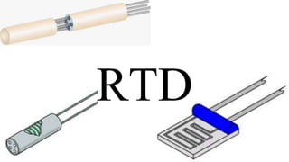
- 4. RTD Element Type ● A platinum or metal glass slurry film deposited or screened onto a small flat ceramic substrate known as "thin film" RTD elements ● Platinum or metal wire wound on a glass or ceramic bobbin and sealed with a coating of molten glass known as "wire wound" RTD elements. ● A partially supported wound element which is a small coil of wire inserted into a hole in a ceramic insulator and attached along one side of that hole.
- 5. ● Nickel behave non linear above 3000C ● Copper oxidizes above 1500C ● Platinum has most stable resistance temperature relationship, its rarely used above 6000C RTD Element Wire
- 6. ● Three wire rtds are the most common specifications for industrial applications. Three wire normally use a wheatstone bridge measurement circuit to compensate for the load wire resistance. ● Two wire rtds do not compensate for the copper resistance associated and gives approximate value ● 4 wire rtds are even more accurate 2,3 & 4 wire RTDs
- 8. Accuracy of RTDs ★ Class A (½ DIN) ★ Class B (DIN) ★ Class AA (⅓ DIN) ★ Class ⅕ DIN ★ Class 1⁄10 DIN
- 9. ● For most RTDs, the calibration temperature is 0°C, and it is understood that any temperature above or below this temperature will have a wider tolerance band and lower accuracy. ● Most RTD sensors will use the Class A or Class B designation as set forth in International Standard IEC 751 and will be denoted simply by their temperature deviations at their reference temperature: Class A, with a tolerance of ±0.15°C at 0°C; or Class B, with a tolerance of ±0.3°C at 0°C. But there are additional class designations such as “1/10 DIN” and “1/3 DIN” used to denote sensors of greater precision and these will have a tolerance of 1/10 or 1/3 of the Class B specification at 0°C
- 10. IEC 751 defines two performance classes for 100Ω Platinum RTDs with alpha 0.00385, Class A and Class B, as follows:
- 11. TYPES OF RTDs ● Head Type RTD ● Transition Joint RTD
- 12. On the basis of process connection and fitting to be used, the temperature, environment condition it has to bear, it is made in different designs with different metal coverings but the rtd element used is same in all.