1. 19th
May 2017
2017-05-19_Guidance on FuelOilMonitoring_rev09-TrackChange.docx
GUIDANCE ON FUEL MONITORING
1 PURPOSE
This paper provides guidance on onboard monitoring of fuel oil and recording of data for the
purpose of monitoring of fuel consumption required by Regulation (EU) 2015/757.
2 RESPONSIBILITIES
The Master has ultimate responsibility for the monitoring of ship’s bunker consumption and
for reporting the data to the office as set by the company’s procedures.
The Chief Engineer is responsible for the overall bunker operations, including the verification
of bunker received, the sounding of the bunker tanks and calculation of the exact quantity of
bunkers onboard.
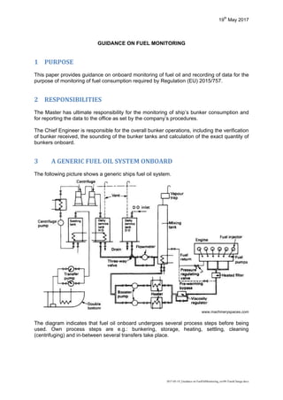
3 A GENERIC FUEL OIL SYSTEM ONBOARD
The following picture shows a generic ships fuel oil system.
www.machineryspaces.com
The diagram indicates that fuel oil onboard undergoes several process steps before being
used. Own process steps are e.g.: bunkering, storage, heating, settling, cleaning
(centrifuging) and in-between several transfers take place.
2. GUIDANCE ON FUEL MONITORING
Page 2 of 10
4 TANKS SOUNDING FUEL OIL MEASUREMENT AND MONITORING
This is a generic guidance for fuel oil measurement through manual sounding / ullage
measurements. Depending on the situation onboard, it should be taken into account that not
all ships may need to follow each step and the frequency of measurements provided below.
4.1 Fuel consumption “in port” and “at sea”
For clarification, the fuel consumption “in port” is the total amount of fuel from the time the
ship arrives at first berth of a port and up to the time the ship leaves the last berth of the port
where commercial cargo operations or embarkation/disembarkation of passenger took place.
For example: a chemical tanker’s “in port” fuel consumption should include the total of the
fuel consumed after the ship is securely moored at the first berth of a port including: fuel
used for cargo operations to that berth and any other berth of the same port, fuel
consumption used by the ship to move from one berth to another berth and fuel consumption
used by the ship for moving out to sea for cargo tank cleaning and return to a berth of the
same port.
The total fuel consumed “in port” can be:
the difference between the fuel measured on board when the ship arrives at the first
berth of a port and the fuel measured on board when the ship leaves the last berth of
the port (eventual fuel bunkered during the stay in the port is not accounted for in this
measurement) ; and
when applicable, the fuel consumed while the ship was waiting at anchor or is
carrying out ship-to-ship transfers within the port area
All other fuel consumption except the above, should be considered as “at sea”.
4.2 Frequency
The frequency of fuel tanks’ stock takings through soundings/ ullages should occur:
(1) For fuel monitoring method A)1
:
a) Upon bunkering and de-bunkering
b) Upon arrival to the first berth of a port2
and before leaving the last berth of the port
where commercial cargo operations or embarkation/ disembarkation of passengers
took place3
prior to engaging on a voyage for a port outside the scope of the
Regulation.
c) For ships in short and regular trades and for ships using shore power while at berth
the measurements may take place either upon arrival at the first berth or before
leaving the last berth.2
d) Allocation of all fuel consumption (for each fuel type) not under the scope of the
regulation is needed as the sum is to be subtracted from the amount provided in the
Bunker Delivery Note (BDN)
(2) For fuel monitoring method B)4
:
a) Upon bunkering and de-bunkering
1
Annex I, Although Method A is based on fuel data from BDN, ships need to measure fuel in tanks to make the balance at the
end of the voyage or the end of the monitoring period…
2
under the scope of the Regulation
3
this may be applicable for fuel monitoring method B) as well
4
Annex I, B Methods for DETERMINING CO2 EMISSIONS, (b) Bunker fuel tank monitoring on board;
3. GUIDANCE ON FUEL MONITORING
Page 3 of 10
b) Fuel tank readings for all bunker tanks onboard should occur daily when the ship is
at sea5
. These could be on a daily basis at 12:00 noon time, the start/end of a canal
crossing, a voyage interruption, etc.
c) While at sea passage prior entry and exit of an Sulphur Emission Control Area
(SECA), if there is a fuel switch.
4.3 Calculating the volume of bunker in each tank
The ship specific sounding / calibration tables produced by shipyard for each individual
bunker tank should be used to determine the volume of bunker in each tank taking into
account the trim and list of the vessel.
ASTM D 1250-80 Standard Guide for Petroleum Measurement, table 54B, or equivalent
tables or a substantiated software for temperature and atmospheric pressure corrections of
density and mass calculations should be used.
The software could additionally be supported by dedicated ship specific software for trim, list
and temperature corrections is available on board.
4.4 Density
Density values to be used could be one of the following:
(a) on-board measurement systems;
(b) the density measured by the fuel supplier at fuel bunkering and recorded on BDN;
(c) the density measured in a test analysis conducted in an accredited fuel test
laboratory, where available.
The source of density values should be stated at all times. However, the fuel oil volumes
recorded onboard after each monitoring may always be related to the standard temperature
of 15o
C 6
.
To cater for most practical handling onboard with the density issue -as an alternative to
above- volume to mass conversion - may be done using standard conversion factors. The
company may use bespoke conversion factors for the entire reporting period subject to
criteria for establishing these have met the agreement of the verifier. The company may also
use the following standard conversion factors:
0.96 when using RME180, RMG 180/380/500/700 or RMK 380/500/700
0.88 when using MGO/MDO
These standard conversion factors derive from ISO 8217 Fuel Standard figures after having
been corrected with ASTM D1250 density temperature variation tables (using 60˚C - 80˚C
for IFO/HFO and 40˚C for MDO/MGO) and apply regardless of whether the volume
measurements are made in the bunker tanks or at a volume flowmeter placed between the
service tank and the engine inlet.
4.5 Density for Commingled bunkers
5
fuel tank readings from tanks that have no transfer nor consumption can be omitted
6
reference is made to: ISO 8217; Specifications of Marine Fuels
4. GUIDANCE ON FUEL MONITORING
Page 4 of 10
When there are 2 types of fuels (or more) are mixed and stored in one fuel tank then the
density volume to mass conversion factor of the fuel tank of the mixed oil should be
calculated as per the below mentioned formula:
`𝐴` 𝑓𝑢𝑒𝑙 𝑣𝑜𝑙𝑢𝑚𝑒 𝑥 𝐷𝑒𝑛𝑠𝑖𝑡𝑦 (𝐴) + `𝐵` 𝑓𝑢𝑒𝑙 𝑣𝑜𝑙𝑢𝑚𝑒 𝑥 𝐷𝑒𝑛𝑠𝑖𝑡𝑦 (𝐵)
`𝐴` 𝑓𝑢𝑒𝑙 𝑣𝑜𝑙𝑢𝑚𝑒 + `𝐵` 𝑓𝑢𝑒𝑙 𝑣𝑜𝑙𝑢𝑚𝑒
= mixed fuel Density
4.6 Density for blended fuels
In the rare event that fuel types with different densities are blended in a tank, the weighted
average density should be determined, unless a density analysis of the mixed fuel sample is
available.
𝜌𝑤 = 𝜌𝑎𝑑𝑑 ×
𝑚𝑎𝑑𝑑
𝑚𝑡𝑜𝑡𝑎𝑙
+ 𝜌𝑒𝑥𝑖𝑠𝑡 ×
𝑚𝑒𝑥𝑖𝑠𝑡
𝑚𝑡𝑜𝑡𝑎𝑙
Where:
ρw : is the weighted average density of fuel in the tank after additions [t/m3
]
ρadd : is the density of the fuel added to the tank [t/m3
]
madd : is the amount of fuel added to the tank [t]
mtotal : is the total amount of fuel in the tank after addition [t]
ρexist : is the density of the existing fuel in the tank before addition [t/m3
]
mexist : is the existing amount of fuel in the tank before addition [t]
4.7 Gauging Equipment
In general, there are several methods of gauging fuel tanks, e.g., manual soundings, gauges
with audible noise when an oil interface is reached, pressure transducers, radar and so forth;
each ship will adapt this part for description according to the equipment they use.
As back-up for fixed installed tank sounding / gauging equipment, the method of
determination of a tank’s sounding or ullage is suggested to be manual soundings. The tape
or measuring device is to be graduated in feet, inches and fractions of an inch; or meters,
centimetres, and millimetres.
Tapes which have been kinked or spliced or which contain illegible markings should not be
used.
4.8 Gauging criteria
Vessel’s equipment used for gauging should always be substantiated for accuracies. This
should be done by:
Checking the condition and calibration (if applicable) of the instrumentation used for
gauging the quantity of bunkers on board
Recording the calibration certification (if applicable).
Visual inspection of ullage tape to ensure there has been no damage to the tape
and/or whether any repairs have been made that may alter readings.
Repeated measurements are taken for each tank to obtain at least two consistent readings.
If two measurements are not similar then an average reading based on at least three
measurements is recommended to do.
5. GUIDANCE ON FUEL MONITORING
Page 5 of 10
5 CONTINUOUS FUEL OIL MONITORING
This procedure is for ships using flowmeters on consumers (e.g. main engines, auxiliary
diesels, inert gas generators, boilers, etc.).
The data from all flow meters linked to fuel consumers minus the data from all flow meters at
the return lines from the same consumers (if applicable) should be combined to determine
fuel consumption over a period7
.
Regardless if the fuel measurements are automatically recorded and transmitted, it is a good
practice for ships engaged in long voyages when at sea, to record daily measurements in
the Engine Logbook. Depending on type of ship operation the master, chief engineer or the
operator may follow other practice as per company SMS.
The validity of fuel flowmeters should be compared on a periodic basis through comparison
with the fuel figures that derive from flowmeters and tank soundings. The ship operator’s
PMS should provide guidance on comparison frequency.
To ensure proper readings, fuel flowmeters onboard should be calibrated as per makers
recommendations or based on the ship’s operational experience if flow meter is maintaining
operational accuracy within manufactures suggested tolerances. Any records of
manufacturer calibration should be maintained onboard and captured within the PMS
onboard.
In the event that a fuel measurement cannot be made due to failure of a flow metering
device the daily fuel consumption should be determined by utilising the tank soundings
method8
.
5.1 Volume flowmeter.
The amount of fuel consumed is determined in units of volume, expressed in litres, and it is
converted to mass by using the density values corrected for the applicable temperature by
the use of the formula below:
𝑀 = 𝜌 × 𝑉
Where:
M: mass of fuel (kg)
V: volume of fuel (l)
ρ: density at applicable temperature (kg/l).
Density values to be used should originate from BDN or provided through a fuel test analysis
conducted in an accredited fuel test laboratory. Source of density values should be stated at
all times.
ASTM D 1250-80 table 54B or equivalent tables or a substantiated software for temperature
corrections of density should be used.
Temperature to be used for density corrections should be the fuel temperature at the
flowmeters.
7
The need for a fuel meter in the return line may not be necessary depending on the arrangements, e.g. on where in the
system the supply meter is fitted
8
means inherently that this is a fall-back solutions for filling (avoiding) data gaps for Methods A), B) and/or C)
6. GUIDANCE ON FUEL MONITORING
Page 6 of 10
5.2 Mass flowmeters
The mass flow meters measures directly the mass flow rate of the fuel and eliminates the
need for further mathematical calculations to derive the mass of fuel consumed.
6 FUEL OIL MONITORING AND RECORDING
This section describes the different sequences of fuel oil handling onboard. This includes
that fuel oil measurements on board ships are (or can be) done for different situations and
purposes. The sequence and procedures in this chapter are generic and not each of them
may apply to all the different ship types and ship trades we are faced with.
Ships may develop (or have) assessment procedures for dealing with possible mistakes or
omissions that could occur and lay down control measures that are to be taken by the
company to minimize this risk for data gaps.
Data flow charts for every fuel oil measurement method in use would be helpful to indicate
the sequence of actions step by step along with the control activities.
6.1 BUNKERING
Bunkering should be covered by routine operational procedures. Therefore, in this guidance
paper a description of bunkering is not included as an own part / chapter. However, to just
provide an info on what could / might be included in such descriptions, an own annex is
attached for informational reasons.
6.2 “NOON REPORT”
As a matter of routine but on a voluntary basis only, ships engaged on long voyages do
report the total amount of fuel on board on a daily basis9
. The report is done at noon local
time where the ship is located. This measurement provides also a daily monitor of the fuel
consumption. The Officer in charge makes relevant entries in the Engine Log Book.
However, ships engaged in shorter voyages may not do this reporting.
6.3 WEEKLY MEASUREMENT
As a matter of best practice for good housekeeping but also to check and confirm proper
function of Mass Flow Meters, Volumetric Flow Meters, ships may measure by manual tank
sounding and make the balance of the fuel oil onboard on a weekly basis.
The procedure to follow was presented under section 3.
The Chief Engineer makes entries into the Engine Room log of the fuel oil remaining on
board (ROB) and, comparing with the previous measurement results, could make the
balance of the total fuel consumed during that week.
9
If you opt for monitoring Method B) it is required, for Method A) and C) it is a suggestion.
7. GUIDANCE ON FUEL MONITORING
Page 7 of 10
6.4 END OF VOYAGE MEASUREMENT
As a matter of best practice for easy monitoring and recording of the fuel consumption for
each voyage, ships do measure the fuel oil ROBs at the end of each voyage or as
determined by company SMS.
The procedure is similar to the one done as presented in section
4.
6.5 FUEL OIL MONITORING IN PORTS
A separated fuel oil monitoring / consumption analysis is required for ships in ports. Although
ships may have various ways to monitor fuel consumption while in port, some ships may
separately assess / calculate it using a method that with a reasonable accuracy establishes
the mass of the individual fuel types consumed during the port stay(s).
6.6 EMISSION FACTORS FOR “NON-STANDARD”-FUELS
Since 1 January 2015, ships have been supplied with an increased number of Ultra Low
Sulphur Fuel Oils (ULSFO) which are new products not yet categorised under the ISO 8217.
In regard of the CO2-conversion factor of these fuels, it is that test results from accredited
laboratories indicate that the large majority of these new products are within the RMA-RMD
grades (i.e. residuals - light fuel oils) and only one or two are categorised as DMB grades
(i.e. distillates).
For simplicity and consistency reasons, it is suggested that such new fuels (so-called
“hybrid-fuels”) should use the standard CO2 - conversion factors applied for light fuel oil (i.e.
3.151 when its viscosity is within RMA to RMD grades) and for distillates (i.e. 3,206 when
similar to DMA or DMZ grades) as per this regulation.
Type of fuel Reference Emission factor (t-CO2/t-fuel)
Distillates (MGO/MDO) ISO 8217 Grades DMA through DMZ 3,206
Light fuel oil (LFO) ISO 8217 Grades RMA through RMD 3,151
The above assignment should not be seen as an exhaustive list as new products might be
provided in the future.
6.7 UNCERTAINTY ASSOCIATED WITH FUEL MONITORING
The quantity determination is inherently subject to uncertainty. The Regulation requires to
specify the uncertainty level within the Monitoring Plan (Art. 6.3.(f).(iv)) as well as in the
Emission Report (Art. 11.3.(c)). Supplementary, uncertainty is further dealt with in
COMMISSION IMPLEMENTING REGULATION (EU) 2016/1927 and COMMISSION
DELEGATED REGULATION (EU) 2016/2072.
To deal comprehensively with the overall uncertainty figure with fuel monitoring on board a
ship, it is to be noted that the measurement accuracy (uncertainty) of single equipment (e.g.
flowmeters for receiving bunkers, density determination, storage in bunker tank,…) provide
not the full picture of uncertainty levels for all processes of fuel oil handling on board.
8. GUIDANCE ON FUEL MONITORING
Page 8 of 10
By way of illustration, all process steps as mentioned in
chapter
3 contributes to the overall
“uncertainty level” to be stated according to the regulation. To serve as best practice within
this guidance document it is proposed (for the time being) to state an overall uncertainty
level as follows:
Monitoring Method acc.
Reg. EU 2015/757
overall max.
uncertainty level
method A) ± 10%
method B) ± 10%
method C) ± 10%
In case the uncertainty will be determined in more detail, the combined uncertainty is
calculated to the following formula:
𝑢𝑐(𝑉) = √𝑢(𝑉, 𝑏𝑢𝑛𝑘𝑒𝑟𝑖𝑛𝑔)² + 𝑢(𝑉, 𝑑𝑒𝑛𝑠𝑖𝑡𝑦)2 + 𝑢(… )² + ⋯
Appendix I
Abbreviations
BDN Bunker Delivery Note
ESSF European Sustainable Shipping Forum
HFO Heavy Fuel Oil
(RME, RMG and RMK grades as per ISO 8217)
IMO International Maritime Organisation
LFO Light Fuel Oil
(RMA, RMB, RMD grades as per ISO 8217)
MARPOL International Convention for the Prevention of Pollution from
Ships
MDO Marine Diesel Oil
(DMA, DMB, DMZ grades as per ISO 8217)
MEPC Maritime Environmental Protection Committee
MGO Marine Gas Oil
(DMX, DMA grades as per ISO 8217)
PMS Plant Management System Planned Maintenance System
RO Recognised Organisation
ROB Fuel Oil Remaining
SECA Sulphur Emission Control Area
SEEMP Ship Energy Efficiency Management Plan
SMS Safety Management System
9. GUIDANCE ON FUEL MONITORING
Page 9 of 10
Appendix II
An example for a general description of bunkering procedures
Chief Engineer or other appointed crew members 10
check ALL bunker tanks and complete
the respective part of the “Bunkers Calculation” Form.
All quantities of bunkers (e.g. HFO, ULSHFO, MGO or other types of LSFOs) are recorded
separately.
Common practice is to plan to receive new bunker in EMPTY bunker tanks. If not possible,
comingling of different fuel batches may happen. In general, comingling is not favourable.
The appointed Engineer Officer has to implement the bunkering plan, supervise bunkering
process and ensure that bunkering procedure is followed throughout the bunkering
operations.
Relevant actions to secure correct assessment of the bunker received:
carry out a pre-bunkering survey of the bunker barge, as per shipping company /
bunker suppliers agreement, in order to determine exact quantity onboard together
with the appointed Deck Officer of the watch.
check ALL bunker tanks.
witness the completion of the ullage report
(for this purpose, the co-operation of bunker barge personnel should be secured)
sign and obtain a copy of the completed ullage report;
the copy should be attached to the Bunker Receipt Form.
inform Master and request approval to start receiving bunkers when both quantity i.e.
own vessel and bunker barge have been completed.
upon completion of the bunkering, the Master and the Chief Engineer should arrange
for a post bunkering survey (own vessel and bunker barge) similarly as with the “pre-
bunkering survey procedures’ above.
the Chief Engineer reviews the BDN and declaration of compliance with
MARPOL Annex VI, presented by the bunker barge.
during the review, Chief Engineer compares received quality and quantity against the
Company’s bunkering information i.e. ordered regarding quality and quantity.
both the Chief Engineer and the Master should sign for acceptance the Bunker
Delivery Note issued by the bunker barge only if they agree with the figures received.
10
or otherwise stated by company procedures
10. GUIDANCE ON FUEL MONITORING
Page 10 of 10
Note : The ship (i.e. the chief engineer on behalf of owner) issues a Letter of Protest in the
following situations, but not limited to:
shortage of bunker delivered,
quality issues (e.g. failure of fulfilling ISO specifications)
slow pumping rate,
ship’s fuel samples not signed by the supplier
lack of co-operation from bunker barge personnel to conduct mutual ullage
inspections.
Upon completion of each bunkering, the following documentation are to be submitted to
ships´ operational Head Office:
1. Bunkering Report Form.
2. Bunkers Quantity Calculation Form
3. Bunkering samples registration and consumption log Form
4. Bunkering pre-loading plan Form
5. Letter of Protest, if applicable
6. Ship-Barge Safety Checklist Form or Ship-Shore Safety Checklist Form, if bunkering
by barge or terminal respectively.
The Chief Engineer should also maintain copies onboard. All relevant forms and checklists
are kept on board for minimum 3 years.
Officer in charge makes relevant entries in the Engine Log Book and in the Oil Record Book.