
Recommended
More Related Content
Viewers also liked
Viewers also liked (6)
Recently uploaded
Recently uploaded (20)
Fischer pressure-transmitter-me01-process-monitoring-liquid-gas
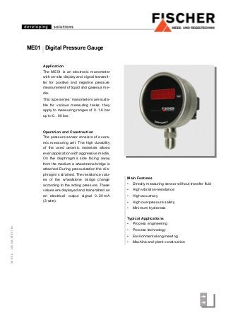
- 1. 30.9.08DB_GB_ME01.fm Application The ME01 is an electronic manometer with on-site display and signal transmit- ter for positive and negative pressure measurement of liquid and gaseous me- dia. This type series’ manometers are suita- ble for various measuring tasks; they apply to measuring ranges of 0..1.6 bar up to 0.. 60 bar. Operation and Construction The pressure sensor consists of a cera- mic measuring cell. The high durability of the used ceramic materials allows even application with aggressive media. On the diaphragm’s side facing away from the medium a wheatstone bridge is attached. During pressurization the dia- phragm is strained. The resistance valu- es of the wheatstone bridge change according to the acting pressure. These values are displayed and transmitted as an electrical output signal 0..20 mA (3-wire). Main Features • Directly measuring sensor without transfer fluid • High vibration-resistance • High accurracy • High overpressure safety • Minimum hysteresis Typical Applications • Process engineering • Process technology • Environmental engineering • Machine and plant construction ME01 Digital Pressure Gauge
- 2. Specifications Measuring range in bar 0-1.6 0-2.5 0-4 0-6 0-10 0-16 0-25 0-40 0-60 Overpressure safety in bar 3.2 5 8 12 20 32 50 80 120 Measuring range in bar - 1..0 -1..0.6 -1..1.5 -1..3 -1..5 -1..9 -1..15 0...-1 Overpressure safety in bar 2 3 3 8 12 20 32 2 Linearity < 1% FS Hysteresis < 0.5% FS Perm. ambient temperature 0 .. 60°C Perm. medium temperature 0 .. 85°C Protection class IP 65 acc. to DIN EN 60529 Electrical Data Nominal power supply 24V DC ± 10% Output signal 0..20 mA / 4..20 mA / 0..10 V Electrical connection 3-wire Max. load 500 Ω (0/4..20 mA); >5k (0..10 V) Current / voltage limiting for output 0..10V: approx. 10.5 V for output 0/4..20 mA: approx. 24 mA Temperature drift, zero 0.4 % FS/10 K Temperature drift, range 0.05 % FS/10 K Connections Electrical connection Connection plug M16 x 1.5 acc. to DIN EN 175301-803 Pressure connection Male connection G ½ acc. to DIN EN 837 Materials Material, medium contact AISI 316L (1.4404), gasket: Viton® Material, body AISI 304 (1.4305)
- 3. Dimensions (all units in mm unless otherwise stated) Electrical Connection 3-wire Output signal Operating voltage Male connection G ½ acc. to DIN EN 837
- 4. Technische Änderungen vorbehalten • Subject to change without notice • Changements techniques sous réserve Fischer Mess- und Regeltechnik GmbH • Bielefelder Str. 37a • D-32107 Bad Salzuflen • Tel. +49 5222 9740 • Fax +49 5222 7170 • eMail: info@fischermesstechnik.de • www.fischermesstechnik.de Ordering Code Digital Pressure Gauge ME01 Measuring Range 0 . . . 1 bar.................................................................> 0 2 0 . . . 1.6 bar.................................................................> 0 3 0 . . . 2.5 bar.................................................................> 0 4 0 . . . 4 bar.................................................................> 0 5 0 . . . 6 bar.................................................................> 0 6 0 . . . 10 bar.................................................................> 0 7 0 . . . 16 bar.................................................................> 0 8 0 . . . 25 bar.................................................................> 0 9 0 . . . 40 bar.................................................................> 1 0 0 . . . 60 bar.................................................................> 1 1 -1 . . . 0 bar.................................................................> 3 1 -1 . . . 0.6 bar.................................................................> 3 2 -1 . . . 1.5 bar.................................................................> 3 3 -1 . . . 3 bar.................................................................> 3 4 -1 . . . 5 bar.................................................................> 3 5 -1 . . . 9 bar.................................................................> 3 6 -1 . . . 15 bar.................................................................> 3 7 Accuracy Linearity error relative pressure 1.0 .................................................> M Linearity error absolute pressure 1.0 (only for ranges ≤16 bar)...................................................................> S Pressure Connection Male connection G 1/2 B stainless steel ...................................................> 8 7 Electrical Output Signal 0 - 20 mA 3-wire (STANDARD)................................................................................> A 0 - 10 V 3-wire (STANDARD)................................................................................> C 4 - 20 mA 3-wire (STANDARD)................................................................................> P Electrical Connection 4-pin connection plug acc. to DIN EN 175 301-803-A ..................................................... > H Power Supply 24 V DC / AC ........................................................................................................................... > L 08 7 H L 000